EP0595965B1 - Conteneur reutilisable pour l'emballage de toutes sortes de marchandises - Google Patents
Conteneur reutilisable pour l'emballage de toutes sortes de marchandises Download PDFInfo
- Publication number
- EP0595965B1 EP0595965B1 EP19920916243 EP92916243A EP0595965B1 EP 0595965 B1 EP0595965 B1 EP 0595965B1 EP 19920916243 EP19920916243 EP 19920916243 EP 92916243 A EP92916243 A EP 92916243A EP 0595965 B1 EP0595965 B1 EP 0595965B1
- Authority
- EP
- European Patent Office
- Prior art keywords
- bottom tray
- reusable container
- kinds according
- packing goods
- goods
- Prior art date
- Legal status (The legal status is an assumption and is not a legal conclusion. Google has not performed a legal analysis and makes no representation as to the accuracy of the status listed.)
- Expired - Lifetime
Links
- 238000012856 packing Methods 0.000 title claims abstract 26
- 238000007373 indentation Methods 0.000 claims description 8
- 238000013016 damping Methods 0.000 claims description 7
- -1 polyethylene Polymers 0.000 claims description 5
- 239000004743 Polypropylene Substances 0.000 claims description 3
- 229920001155 polypropylene Polymers 0.000 claims description 3
- 239000004698 Polyethylene Substances 0.000 claims description 2
- 229920000573 polyethylene Polymers 0.000 claims description 2
- 230000001747 exhibiting effect Effects 0.000 claims 4
- 230000006835 compression Effects 0.000 claims 1
- 238000007906 compression Methods 0.000 claims 1
- 238000006073 displacement reaction Methods 0.000 claims 1
- 229920002994 synthetic fiber Polymers 0.000 claims 1
- 230000006378 damage Effects 0.000 abstract description 4
- 239000000945 filler Substances 0.000 abstract 1
- 239000004033 plastic Substances 0.000 description 18
- 229920003023 plastic Polymers 0.000 description 18
- 101150006573 PAN1 gene Proteins 0.000 description 8
- 230000000694 effects Effects 0.000 description 5
- 238000004806 packaging method and process Methods 0.000 description 5
- 239000000463 material Substances 0.000 description 3
- 239000002699 waste material Substances 0.000 description 2
- 238000003466 welding Methods 0.000 description 2
- 241001417534 Lutjanidae Species 0.000 description 1
- 229910052782 aluminium Inorganic materials 0.000 description 1
- XAGFODPZIPBFFR-UHFFFAOYSA-N aluminium Chemical compound [Al] XAGFODPZIPBFFR-UHFFFAOYSA-N 0.000 description 1
- 230000015572 biosynthetic process Effects 0.000 description 1
- 238000005474 detonation Methods 0.000 description 1
- 238000005755 formation reaction Methods 0.000 description 1
- 230000003993 interaction Effects 0.000 description 1
- 229910052751 metal Inorganic materials 0.000 description 1
- 239000002184 metal Substances 0.000 description 1
- 238000000034 method Methods 0.000 description 1
- 238000003825 pressing Methods 0.000 description 1
- 230000002787 reinforcement Effects 0.000 description 1
- 238000007789 sealing Methods 0.000 description 1
- 238000000926 separation method Methods 0.000 description 1
- 239000007921 spray Substances 0.000 description 1
Images







Classifications
-
- B—PERFORMING OPERATIONS; TRANSPORTING
- B65—CONVEYING; PACKING; STORING; HANDLING THIN OR FILAMENTARY MATERIAL
- B65D—CONTAINERS FOR STORAGE OR TRANSPORT OF ARTICLES OR MATERIALS, e.g. BAGS, BARRELS, BOTTLES, BOXES, CANS, CARTONS, CRATES, DRUMS, JARS, TANKS, HOPPERS, FORWARDING CONTAINERS; ACCESSORIES, CLOSURES, OR FITTINGS THEREFOR; PACKAGING ELEMENTS; PACKAGES
- B65D81/00—Containers, packaging elements, or packages, for contents presenting particular transport or storage problems, or adapted to be used for non-packaging purposes after removal of contents
- B65D81/02—Containers, packaging elements, or packages, for contents presenting particular transport or storage problems, or adapted to be used for non-packaging purposes after removal of contents specially adapted to protect contents from mechanical damage
-
- B—PERFORMING OPERATIONS; TRANSPORTING
- B65—CONVEYING; PACKING; STORING; HANDLING THIN OR FILAMENTARY MATERIAL
- B65D—CONTAINERS FOR STORAGE OR TRANSPORT OF ARTICLES OR MATERIALS, e.g. BAGS, BARRELS, BOTTLES, BOXES, CANS, CARTONS, CRATES, DRUMS, JARS, TANKS, HOPPERS, FORWARDING CONTAINERS; ACCESSORIES, CLOSURES, OR FITTINGS THEREFOR; PACKAGING ELEMENTS; PACKAGES
- B65D81/00—Containers, packaging elements, or packages, for contents presenting particular transport or storage problems, or adapted to be used for non-packaging purposes after removal of contents
- B65D81/02—Containers, packaging elements, or packages, for contents presenting particular transport or storage problems, or adapted to be used for non-packaging purposes after removal of contents specially adapted to protect contents from mechanical damage
- B65D81/05—Containers, packaging elements, or packages, for contents presenting particular transport or storage problems, or adapted to be used for non-packaging purposes after removal of contents specially adapted to protect contents from mechanical damage maintaining contents at spaced relation from package walls, or from other contents
- B65D81/07—Containers, packaging elements, or packages, for contents presenting particular transport or storage problems, or adapted to be used for non-packaging purposes after removal of contents specially adapted to protect contents from mechanical damage maintaining contents at spaced relation from package walls, or from other contents using resilient suspension means
-
- Y—GENERAL TAGGING OF NEW TECHNOLOGICAL DEVELOPMENTS; GENERAL TAGGING OF CROSS-SECTIONAL TECHNOLOGIES SPANNING OVER SEVERAL SECTIONS OF THE IPC; TECHNICAL SUBJECTS COVERED BY FORMER USPC CROSS-REFERENCE ART COLLECTIONS [XRACs] AND DIGESTS
- Y02—TECHNOLOGIES OR APPLICATIONS FOR MITIGATION OR ADAPTATION AGAINST CLIMATE CHANGE
- Y02W—CLIMATE CHANGE MITIGATION TECHNOLOGIES RELATED TO WASTEWATER TREATMENT OR WASTE MANAGEMENT
- Y02W30/00—Technologies for solid waste management
- Y02W30/50—Reuse, recycling or recovery technologies
- Y02W30/80—Packaging reuse or recycling, e.g. of multilayer packaging
Definitions
- the invention relates to a reusable container for the packaging of goods of all kinds, consisting of a top and a bottom tray, each with a groove running all around on the inside edges and a ring forming the side walls, foldable after use, which during use into the grooves running all around two trays can be inserted, and means for holding the three parts together during use.
- reusable containers which consist of a top and bottom tray, preferably made of polypropylene, and a collapsible cardboard ring forming the side walls.
- closures attached to the side edges of the bottom and top troughs are used.
- the circumferential edges of the lid and the base tray interlock and thus protect the inner box.
- a firm connection of the lid and floor pan is not provided, so that the individual parts can fall apart if handled carelessly.
- Another disadvantage of this known reusable container is that the packaged goods can only be fixed by filling material that is generated as waste after use.
- this type of fixation of the packaged goods cannot achieve sufficient slip resistance of the packaged goods, so that there is an increased risk of transport damage, especially in the case of sensitive packaged goods.
- the object of the present invention is to provide a reusable container for packaging goods of all kinds, in particular sensitive electronic devices, which has a secure and quickly detachable connection of its individual parts as well a time-saving and non-slip fixation of the packaged goods before and an easy releasability of this fixation after transport, while allowing the packaged goods to be protected from damage during transport.
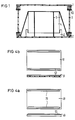
- the reusable container consists of three parts, namely the deck pan 1, the floor pan 2 and the ring 3 in between.
- On the floor pan there may be holding options for accommodating a damping insert 42 and inner belts 5 provided that fix the packaged goods 4 non-slip during transport.
- Several configurations 63 which will also be discussed later, are possible for holding the three parts together.
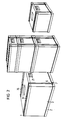
- the reusable containers can be designed in different widths and heights, as shown in FIG. These reusable containers can also be stacked one on top of the other, plastic strips 76 with a curved surface being arranged on the outside cover surface 49 of the cover trough 1 and running parallel to the two long sides 48 of the cover trough 1.
- channels 52 are provided, which are designed in their profile as a negative to the profile of the plastic strips 76, so that when two containers are placed one above the other the surface of the plastic strips 76 lie in the grooves 52 and thus ensure that several containers are stacked securely on top of one another.
- FIGS. 4a and 4b The interaction of the outside cover surface 49 of the deck pan 1 and the bottom pan outer surface 51 of the bottom pan 2 is shown in FIGS. 4a and 4b, FIG. 4a showing a plan view of the outside deck surface 49 of the deck pan 1 and an associated side view, while in FIG Floor pan outer surface is shown from below and the corresponding cross-section.
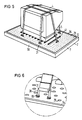
- the fastening of the packaged goods 4 on the inside of the floor pan 12 of the floor pan 2 is shown in FIG. 5.
- the packaged goods 4 are attached to the inside of the floor pan 12 of the floor pan 2 in a non-slip manner by the inner straps 5.
- the inner belts 5 are fixedly connected at one end to U-shaped retaining brackets 31, the side legs 30 of which, as shown in FIG. 6, can be inserted into grid-shaped, cylindrical depressions 29, the side legs of the retaining bracket 30 having disks 65 at their lower ends which, after the clips have been pressed into the cylindrical depressions 29, clamp behind the edge of the cylindrical depressions, as a result of which it is no longer possible to pull the clips out when the inner straps 5 are tensioned.
- the inner straps 5 are attached to the horizontal part of the bracket 31 by being pulled through the bracket and folded over, the flap being clamped together with rivet or other connections with the lower belt part, whereby a firm connection with the U-shaped bracket 31 takes place .
- a groove 64 runs around the outer edge of the base trough 2 and serves to receive the ring 3, as explained below.
- the packaged goods 4 stand on rubber or plastic strips 41, which in turn have a curved surface and which have projections 40 on the underside of the rubber or plastic strip 41 in the cylindrical shape provided Wells 29 can be snapped into place. If these strips are designed as plastic strips 41, they can also be molded onto the outside cover surface 49 of the cover trough 1.
- the cavity 45 of the floor pan 2 consists of two separate chambers 78, 79, of which the first chamber 78 forms a bead-like ring around the periphery of the floor pan 2 and the second chamber 79 forms an enclosed air chamber by welding to the first chamber 78.
- the bottom of the second chamber 79 is raised relative to the bottom of the first chamber 78, so that the second chamber 79 has a smaller depth than the first. This creates a resilient effect for the packaged goods.
- the separation of the two chambers takes place in that the outer side 27 of the floor pan is pulled up in a V-shape at a predetermined distance from the outer edge and is welded there to the floor pan inside 12.
- the long sides of the floor pan 2 are partially designed as foldable closure surfaces 80, on which a plurality of pressure closures 81 are arranged, which are formed on the back with an extension 82 which, when the closure surfaces 80 are folded down, protrudes through the ring 3 at respectively formed openings 83 and also with a formed one bump-shaped part 84 snaps into a recess 85 on the floor pan 2.
- the shaped lugs 82 dip into the recesses 89. As a result, the ring and base pan 2 are firmly connected. The same connection can be made between deck 1 and ring 3.
- the lock is secured by sealing, locking and the like.
- FIGS. 7, 9 and 10 show the depressions 29 for receiving retaining brackets for the inner belts 5 and also FIG. 10 shows the grooves 86 for receiving the rubber or plastic strips 41. If these strips are made of plastic, could you also be formed on the inside of the floor pan 12.
- the pressure closure 81 can be seen in cross section from FIG. The pressure lock runs out on its rear side into a shoulder 82 which has a cam-shaped bulge 84 on its steep flank. When the closure surface is folded down, the lugs 82 project through the openings 83 of the ring 3 and the cam-shaped bulge, engages in a detent depression 85 on the base trough 2. As a result, the ring 3 is firmly connected to the floor pan. The same applies to the deck tub. There is also a groove-like bulge 88 on the outside of the floor pan 27.
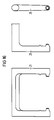
- FIG. 16 shows the handle 21 in a top view, in a bottom view and in a side view.
- FIG. 17 Another embodiment of the floor pan 2 is shown in FIG. 17. It is also a hollow body, which can be produced, for example, by the blow-spray process. Through the cavity 45, a shock-absorbing effect is achieved, which protects the packaged goods 4 from destruction even if the goods to be handled are handled improperly.
- the cylindrical depressions 29, which, as already described above, serve to fasten the retaining brackets 31 or the rubber or plastic strips 41 4 further depressions 46 are provided in the vicinity of the attachment space 47 for the packaged goods, which extend almost to the inner bottom 28 of the The floor pan is sufficient and, when the hollow floor pan 2 is pressed together, may sit on the inner floor 28 of the floor pan 2 due to possible impact loads, thus causing an additional resilient effect.
- FIG. 18 shows the arrangement of the rubber or plastic strips 41 on the top sheet 47 of the packaged goods 4 again schematically.
- FIG. 19 shows another possibility. Instead of the rubber or plastic strips 41, plastic bumps 48 are already provided on the inside of the floor pan, which additionally cause an anti-slip effect.
- a further possibility of fastening the inner straps 5 to the inside of the floor pan is, as shown in FIG. 20, that instead of the cylindrical depressions 29 cuboid depressions 33 are provided which have a projecting edge 34 on their upper side. Clamping catches 35 are snapped into these rectangular recesses 33 and prevented from being pulled out by lugs 67 arranged on the clamping catches 35. By compressing the resilient clamping catch 35, it can be removed again from the cuboid recess 33. The inner straps 5 are then attached to the tensioning catch 35 itself.
- a cross section through a cuboid depression 33 is shown in FIG. Also in one embodiment, as shown in FIG.
- U-shaped brackets can be pressed into the cuboid depressions 33, an embodiment being shown in FIG. 22 in which two holding straps 5 are attached to a further holding bracket 66, the further holding bracket 66 represents only a variant of the bracket 31, as described in FIG 6.
- FIG. 23 A fourth possibility of holding the inner straps 5 is shown in FIG. 23.
- webs 36 are cast into the floor pan 2, which have openings 37 through which one end of the holding straps 5 is pulled, so that a loop can be formed.
- the floor pan 2 is not shown in a simplified manner as a hollow body, as described above.
- a cushion 42 is provided between the base pan 2 and the packaged goods 4 for receiving the packaged goods 4 in such an embodiment, which cushion has a resilient effect.
- FIG. 24 shows a fifth possibility of fastening the inner belts on the inside of the floor pan 12.
- the inner belts 5 are arranged parallel to the circumferential grooves 64 for receiving the ring 3 slide rails 11 on the inside of the bottom pan or in the bottom of the bottom pan itself, which are provided with slots 68, in which sliding blocks 10, which are attached to the ends of the straps 5, are slidably arranged .
- the free ends of the inner straps 5 are provided with closures, which can be designed as hooks or as tension locks. This ensures that no chafing occurs on the packaged goods.
- a defined tightening torque can be set in that, for example, as shown in FIG.
- a control device for detecting the belt tension which consists in that an elastic band 70 is attached to one point of the inner belts 5 such that between the two Hang the inner straps 5 with the elastic band 70. If the inner belts 5 are tightened, the elastic band 70 is tensioned and the end position for the respective inner belt 5 is reached and thus also the predetermined tightening torque.
- the fasteners are captive, for example connected to the inner straps 5 by riveting, screwing or welding.
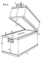
- FIG. 1 A first embodiment of the deck trough 1 is shown in perspective in FIG. It is assumed that the three parts, deck pan 1, ring 3 and floor pan 2, are held together by outer straps 6. These outer belts 6 are fastened to the floor pan 2 and are tensioned with slide clamp closures 9 attached to the deck pan 1. The outer belts 6 are guided in grooves 13 of the outer surface 49 along their long sides 50. The plastic strips 76 are again attached along these longitudinal sides 50 and above the outer straps 6. Additional plastic strips 53 which have a flat surface can also be provided between these two plastic strips 76. They increase the rigidity of the deck trough 1 of reusable containers. On the narrow sides of the deck trough 1, handles 21 are attached which can be pivoted through 180 ° via a hinge 22. These handles have on their side opposite the hinge 22 Formations 23, which are both intended to make carrying easier and also serve as a snap lock when the reusable containers are folded, this lock engaging in the provided positions on the floor pan 2 and the deck and floor pan firmly locked together.
- FIG. 27 A second form of designing the deck trough 1 is shown in FIG. 27.
- slide closures are arranged on the longitudinal sides 50 of the outside surface of the deck trough 1, which can be actuated via sliders 38.
- This embodiment also has handles 21, as already described in FIG. 16.
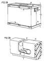
- FIG. 28 shows a reusable container with a sliding closure for holding the three container parts together.
- the ring 3 is inserted into the base trough 2 and the cover trough 1 is placed onto the ring 3.
- Bottom pan 2 and deck pan 1 are fastened to the ring 3 by slide closures with the slides 38.
- the plastic strips 76 can again be seen on the outside cover surface 29 of the cover trough 1.
- the cover trough 1 again has handles 21, and on the front of the ring 3 the fold line 54 of the ring 3 can be seen, along which the ring 3 can be folded after use.
- FIG. 29 The mode of operation of the sliding closure can be seen in detail from FIG. 29.
- the slides 38 which are not shown, there are cylindrically shaped spear bolts 61 which, when the deck pan 1 or the floor pan 2 are placed, retract into the vertical part of the right-angled backdrop 62 and are then located at the lower end of the vertical part of the backdrop 62 . Then they are moved horizontally to the right via the slider 38, so that the top and bottom trough is then firmly connected to the ring 3.
- the link guides 62 can be seen on the reinforced edge of the ring 3.
- the reinforcement can be made of rails 72 with a material stronger than that of the ring.
- the ring 3 shows the same ring 3 in a partially folded position, the two narrow surfaces being folded along the fold line 54.
- the ring 3 can be inserted into the floor pan after use.
- the deck pan is placed over it and locked to the bottom pan, for example via the handles 21, as already stated above, so that after use the deck and bottom pan serve simultaneously as a return container for the ring 3.
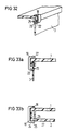
- a third possibility of holding the three parts together is that a bracket 19 articulated on the outside of the deck tub or on the outside of the bottom tub 27, as shown in FIG. 32, snaps into the second recesses provided on the edges of the ring 3, with the unsupported end of the bracket a knob 25 is provided which causes the bracket 19 to snap into place.
- the function of the holding action of the handle 19 is shown again in cross section in FIG. 33a.
- This handle can then also be used at the same time as a closure when the reusable packaging is folded by, as shown in FIG. 33, a corresponding recess 26 is provided on the outside of the bottom pan 27 in which the knob 25 engages and thereby holds the top and bottom trays together.
- a fourth possibility of joining the three parts together as shown in FIG.
- cover trough 1 and the base trough 2 have foldable side walls 14, to which pipe pieces 15 are fastened, which engage after the folding in first recesses 16 of the ring and from can be locked at the rear via a sliding push-through rod, not shown, via sliding keys 17.
- a fifth possibility of locking is possible in that according to FIG. 35, indentations are provided in the side parts of the top and bottom shell, which can also be actuated by pressing and then snap into the first recesses 16 of the ring.
- An effective locking of the three parts can also be brought about in that pockets are provided on the side walls of the top and bottom tubs, in which a sliding bar 56, as shown in FIG. 36, is inserted resiliently via springs 57 , and which are provided on their underside with right-angled hooks 60 which snap into the first recesses 16 of the ring 3 after being displaced, in the same places where the first recesses of the ring 3 lie, in the side walls of the top and bottom trough recesses 69 are also introduced.
- damping insert 42 can be fastened in various ways to the inner floor 28 of the floor pan 2, for example by making square or cylindrical recesses 71, 73 in the floor pan, which are provided with clamping webs 43. A top view and the respective section through such a chamber is shown in FIG. 37.
- FIG. 38 Another fastening option is provided with the aid of a Velcro strip 44, as shown in FIG. 38.
- the push button principle can also be used advantageously.
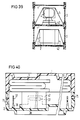
- FIG. 39 A cross section through two stackable reusable containers with different packaged goods 4 is shown in FIG. 39, with this arrangement starting from a floor pan without a cavity, so that a damping insert 42 is provided between the floor pan and the packaged goods.
- the packaged goods themselves are fixed non-slip again via the inner straps 5. If one forms the outside cover surface of the deck trough 1 like the inside surface of the bottom trough 2, the packaged goods 4 of the next container can be placed directly onto the deck trough 1 of the lower container, so that one trough can be saved.
- the floor pan 2 contains fastening webs 36 for fastening the inner straps 5, not shown, and a cushion 42 as a spring element.
- the folded ring 3 lies on the cushion element, and the Deck pan 1 is held together with the floor pan via snap locks 75, so that the return of the reusable container can take place in this state.
- the top and bottom tray of the reusable container can be made of plastic, e.g. Polyethylene or polypropylene, while the ring can be made of cardboard in a simple manner. However, other materials can also be used, for example plastic or aluminum for the ring.
- the floor and deck pan could also be made of light metal.
Landscapes
- Engineering & Computer Science (AREA)
- Mechanical Engineering (AREA)
- Rigid Containers With Two Or More Constituent Elements (AREA)
- Packages (AREA)
- Details Of Rigid Or Semi-Rigid Containers (AREA)
- Packaging Of Machine Parts And Wound Products (AREA)
Claims (25)
- Conteneur réutilisable pour l'emballage de produits de tous types, constitué notamment par une cuvette supérieure et une cuvette inférieure (1,2) comportant respectivement une rainure circonférentielle qui est ménagée dans les bords latéraux intérieurs, et une bague (3) formant les parois latérales et repliable après utilisation et qui, pendant l'utilisation, peut être enfichée dans les rainures circonférentielles (64) des deux cuvettes, ainsi que des moyens pour maintenir assemblés les trois éléments pendant leur utilisation, caractérisé par le fait qu'au moins une cuvette (1,2), de préférence la cuvette inférieure (2), est réalisée sous la forme d'un corps creux, que la fixation du produit à emballer (4) est réalisée au moyen d'une sangle intérieure imperdable (5), qui peut être tendue d'une manière continue et est fixée à la cuvette inférieure (2), et que les moyens servant à maintenir assemblés les trois éléments (1,2,3) sont fixés, après l'utilisation, sur l'une des cuvettes (1,2).
- Conteneur réutilisable pour l'emballlage de produits de tous types suivant la revendication 1, caractérisé par le fait que la cavité (45) de la cuvette inférieure (2) est constituée par deux chambres séparées (78,79), dont la première (78) forme un anneau en forme de rebord sur la périphérie de la cuvette inférieure (2) et dont la seconde (79) forme la partie centrale entourée par la première forme (78) et dont le fond est cependant surélevé par rapport au fond de la première chambre (78) de sorte que la seconde chambre (79) possède une profondeur inférieure à celle de la première.
- Conteneur réutilisable pour l'emballage de produits de tous types suivant l'une des revendications 1 ou 2, caractérisé par le fait que les moyens pour maintenir assemblés les trois éléments pendant l'utilisation sont constitués par des sangles extérieures (6), qui sont fixées, sur l'un de leur côté, dans des ouvertures (7) ménagées dans les parois latérales (8) de la cuvette inférieure (2) et sont pourvues sur leurs autres extrémités, d'un système de fermeture à serrage avec glissement ou patinage (9), pouvant être serré et débloqué.
- Conteneur réutilisable pour l'emballage de produits de tous types suivant l'une des revendications 1 ou 2, caractérisé par le fait que les moyens pour maintenir assemblés les trois éléments pendant l'utilisation sont constitués par des surfaces de fermeture rabattables (89), qui sont réalisés en tant que partie des parois latérales (14) des deux cuvettes (1,2) et sont pourvus, au niveau de leur face intérieure, d'éléments tubulaires (15) disposés en série et qui s'engagent dans des premiers évidements (16) de la bague et peuvent être verrouillés au moyen de tiges enfichables déplaçables ou au moyen de verrous extérieurs (17).
- Conteneur réutilisable pour l'emballage de produits de tous types suivant l'une des revendications 1 ou 2, caractérisé par le fait que les moyens pour assembler les trois éléments sont constitués par des barrettes coulissantes (56) suspendues élastiquement sur les côtés longitudinaux (58,59) de la cuvette supérieure (1) et de la cuvette inférieure (2), sur la face inférieure desquelles sont disposés les crochets (60), qui s'engagent, lors du déplacement, dans des évidements (16) de la bague (3).
- Conteneur réutilisable pour l'emballage de produits de tous types suivant l'une des revendications 1 ou 2, caractérisé par le fait que les moyens pour maintenir assemblés les trois éléments sont constitués par des poussoirs (38) qui sont disposés sur les côtés longitudinaux (58,59) de la cuvette supérieure (1) et de la cuvette inférieure (2) et qui possèdent des verrous de blocage cylindriques sur leur côté arrière et qui, lors de la mise en place de la cuvette supérieure (1) et de la cuvette inférieure (2) sur la bague (3), s'engagent dans des coulisses conformées à angle droit (62).
- Conteneur réutilisable pour l'emballage de produits de tous types suivant l'une des revendications 1 ou 2, caractérisé par le fait que les moyens pour maintenir assemblés les trois éléments pendant l'utilisation sont constitués par des surfaces de fermeture rabattables (80), qui sont formés en tant que parties des parois latérales (14) des deux cuvettes (1,2) et contiennent des parties rentrantes pouvant être enfoncées à partir de l'extérieur et qui s'encliquettent dans des premiers évidements (16) de la bague.
- Conteneur réutilisable pour l'emballage de produits de tous types suivant l'une des revendications 1 ou 2, caractérisé par le fait que les moyens pour maintenir assemblés les trois éléments pendant l'utilisation sont constitués par des étriers en forme de U, qui sont montés de manière à pouvoir basculer sur la face extérieure de la cuvette supérieure et de la cuvette inférieure et qui s'encliquettent dans des seconds évidements ménagés dans les bords de la bague.
- Conteneur réutilisable pour l'emballage de produits de tous types suivant l'une des revendications 1 ou 2, caractérisé par le fait que les moyens pour maintenir assemblés les trois éléments pendant l'utilisation sont constitués par des surfaces de fermeture rabattables (80) qui sont réalisées en tant que parties des parois latérales (14) de la cuvette supérieure (1) et de la cuvette inférieure (2) et qui sont équipés de systèmes de fermeture à pression (81), sur lesquels est formé, sur le côté arrière, un appendice saillant (82), qui lors du rabattement des surfaces de fermeture (80), traverse la bague (3) au niveau de passages respectivement préformés (83) et s'encliquette, par une partie en forme de bouton (84) également formée par moulage, dans une cavité d'encliquetage (85) ménagée dans la cuvette supérieure (1) ou dans la cuvette inférieure (2).
- Conteneur réutilisable pour l'emballage de produits de tous types suivant l'une des revendications précédentes, caractérisé par le fait que sur deux côtés opposés de la cuvette supérieure sont fixées des poignées (21) rabattables sur 180° et qui possèdent, sur le côté tourné à l'opposé de la charnière de poignée (22), des moulures (23), qui s'engagent dans des fentes ménagées dans la paroi latérale (8) de la cuvette inférieure (2) ou s'engagent autour du bord inférieur (24) de la cuvette inférieure (2).
- Conteneur réutilisable pour l'emballage de produits de tous types suivant l'une des revendications 8 et 10, caractérisé par le fait que l'extrémité non supportée de l'étrier en forme de U (19) entoure le bord inférieur (24) de la cuvette inférieure (2) et s'engage, par un bouton d'encliquetage (25) situé sur l'extrémité de l'étrier, dans un renfoncement (26) ménagé dans la face extérieure (27) de la cuvette inférieure (2).
- Conteneur réutilisable pour l'emballage de produits de tous types suivant l'une des revendications précédentes, caractérisé par le fait que sur la face intérieure (12) de la cuvette inférieure sont disposés des renfoncements cylindriques (29) disposés suivant un réseau, qui ne s'étendent pas jusqu'au fond intérieur (28) de la cuvette inférieure (2) et dans lesquels peuvent être encliquetées les branches latérales (30) d'étriers de retenue (31,66) réalisés en forme de U et auxquels sont fixées, par une de leurs extrémités, les sangles intérieures (5), les autres extrémités des sangles intérieures (5) comportant des systèmes de fermeture réglables (32), ce qui permet de mettre sous tension les sangles intérieures (5).
- Conteneur réutilisable pour l'emballage de produits de tous types suivant l'une des revendications 1 à 11, caractérisé par le fait que sur la face inférieure (12) de la cuvette inférieure sont disposés des renfoncements quadrangulaires (33), qui ne s'étendent pas jusqu'au fond à l'intérieur (28) de la cuvette inférieure (2) et qui se rétrécissent, au niveau de leur côté supérieur, grâce à la présence d'un bord saillant (34), et que dans ces renfoncements quadrangulaires (33) peuvent être encliquetés des dispositifs d'encliquetage de serrage (35) pourvus de becs (67) et auxquels sont fixées les extrémités des sangles intérieures (5), les autres extrémités des sangles intérieures (5) possédant des éléments de fermeture réglables (32), ce qui permet de serrer progressivement les sangles intérieures.
- Conteneur réutilisable pour l'emballage de produits de tous types suivant l'une des revendications 1 à 11, caractérisé par le fait que le long de la périphérie de la face intérieure (12) de la cuvette inférieure s'étendent des glissières (11), dans lesquelles sont disposés, de manière à être déplaçables, des coulisseaux (10), qui sont reliés à des premières extrémités des sangles intérieures (5), les autres extrémités des sangles intérieures (5) possédant des systèmes de fermeture réglables, de sorte que les sangles intérieures (5) peuvent être tendues progressivement.
- Conteneur réutilisable pour l'emballage de produits de tous types suivant l'une des revendications 1 à 11, caractérisé par le fait que dans le fond intérieur (28) de la cuvette inférieure (2) sont formées des barrettes (36) qui font salle vers le haut et sont pourvues de passages (37), dans lesquels sont fixées les premières extrémités des sangles intérieures (5), dont les autres extrémités possèdent des systèmes de fermeture réglables de sorte que les sangles intérieures (5) peuvent être tendues progressivement.
- Conteneur réutilisable pour l'emballage de produits de tous types suivant l'une des revendications 12 à 15, caractérisé par le fait qu'une bande élastique (70) est disposée en un emplacement des sangles intérieures (5) de telle sorte que les sangles intérieures (5) sont dans une position pendante.
- Conteneur réutilisable pour l'emballage de produits de tous types suivant l'une des revendications précédentes, caractérisé par le fait qu'à l'emplacement (47) de montage du produit à emballer (4), sur la face intérieure (12) de la cuvette inférieure sont serrées, dans les renfoncements (39), des barrettes en caoutchouc ou en matière plastique (41), qui sont réalisées avec une forme semi-circulaire en coupe transversale et comportent, au niveau de leur face inférieure, des appendices saillants (40) adaptés aux renfoncements (39), et sur lesquelles est situé le produit à emballer (4), ou bien les barrettes en matière plastique sont formées conjointement sur la face intérieure de base (12).
- Conteneur réutilisable pour l'emballage de produits de tous types suivant l'une des revendications 1 à 16, caractérisé par le fait qu'au centre de la face intérieure (12) de la cuvette inférieure est prévu un insert d'amortissement (42) qui est adapté au produit à emballer (4), est réalisé en matière plastique et peut être fixé au fond par l'intermédiaire de systèmes de fermeture amovibles, comme par exemple des barrettes de serrage (43), des boutons-poussoirs ou des bandes adhésives (4).
- Conteneur réutilisable pour l'emballage de produits de tous types suivant l'une des revendications 1 à 16, caractérisé par le fait qu'au niveau de l'emplacement (47) prévu pour la mise en place du produit à emballer (4), sur la face intérieure (12) de la cuvette inférieure il est prévu des bossages (48) qui font saillie à partir de la surface de fond et sont disposés sous la forme d'un réseau.
- Conteneur réutilisable pour l'emballage de produits de tous types suivant l'une des revendications précédentes, caractérisé par le fait que sur la face intérieure (12) de la cuvette inférieure, de préférence autour de l'emplacement (47) de mise en place du produit à emballer (4) sont prévus d'autres renfoncements (46) qui s'étendent en profondeur presque sur toute la cavité (45) de la cuvette inférieure.
- Conteneur réutilisable pour l'emballage de produits de tous types suivant l'une des revendications précédentes, caractérisé par le fait que la surface supérieure extérieure (49) de la cuvette supérieure (1) sont agencés de la même manière que les côtés intérieurs (12) de la cuvette inférieure.
- Conteneur réutilisable pour l'emballage de produits de tous types suivant l'une des revendications précédentes, caractérisé par le fait que des barrettes en matière plastique (76) possédant une section transversale de forme semi-circulaire sont également disposées sur la cuvette inférieure (1), au-dessus des rainures (13) de la surface supérieure (49), et que des rainures (52) possédant un profil qui correspond à celui des barrettes en matière plastique (76), sont prévues au même emplacement de la surface supérieure extérieure (50) de la cuvette inférieure.
- Conteneur réutilisable pour l'emballage de produits de tous types suivant l'une des revendications précédentes, caractérisé par le fait qu'entre les deux barrettes extérieures en matière plastique (76) possédant une surface cintrée, d'autres barrettes en matière plastique (53) possédant une surface plane sont disposées sur la surface supérieure extérieures (49) de la cuvette supérieure (1).
- Conteneur réutilisable pour l'emballage de produits de tous types suivant l'une des revendications précédentes, caractérisé par le fait que la bague (3) peut être repliée à la manière d'un soufflet gonflable, autour de la ligne centrale verticale (5) d'un petit côté (55).
- Conteneur réutilisable pour l'emballage de produits de tous types suivant l'une des revendications précédentes, caractérisé par le fait que la cuvette supérieure (1) et la cuvette inférieure (2) sont réalisées de préférence en matière plastique, tel que du polyéthylène ou du polypropylène, et le noyau (3) est réalisé en carton.
Priority Applications (1)
| Application Number | Priority Date | Filing Date | Title |
|---|---|---|---|
| EP19920916243 EP0595965B1 (fr) | 1991-07-23 | 1992-07-21 | Conteneur reutilisable pour l'emballage de toutes sortes de marchandises |
Applications Claiming Priority (4)
| Application Number | Priority Date | Filing Date | Title |
|---|---|---|---|
| EP91112361 | 1991-07-23 | ||
| EP91112361 | 1991-07-23 | ||
| EP19920916243 EP0595965B1 (fr) | 1991-07-23 | 1992-07-21 | Conteneur reutilisable pour l'emballage de toutes sortes de marchandises |
| PCT/EP1992/001663 WO1993001992A1 (fr) | 1991-07-23 | 1992-07-21 | Conteneur reutilisable pour l'emballage de toutes sortes de marchandises |
Publications (2)
| Publication Number | Publication Date |
|---|---|
| EP0595965A1 EP0595965A1 (fr) | 1994-05-11 |
| EP0595965B1 true EP0595965B1 (fr) | 1994-12-14 |
Family
ID=8206968
Family Applications (1)
| Application Number | Title | Priority Date | Filing Date |
|---|---|---|---|
| EP19920916243 Expired - Lifetime EP0595965B1 (fr) | 1991-07-23 | 1992-07-21 | Conteneur reutilisable pour l'emballage de toutes sortes de marchandises |
Country Status (5)
| Country | Link |
|---|---|
| EP (1) | EP0595965B1 (fr) |
| JP (1) | JPH07115706B2 (fr) |
| AT (1) | ATE115494T1 (fr) |
| DE (1) | DE59200995D1 (fr) |
| WO (1) | WO1993001992A1 (fr) |
Cited By (1)
| Publication number | Priority date | Publication date | Assignee | Title |
|---|---|---|---|---|
| EP4674782A1 (fr) * | 2024-07-02 | 2026-01-07 | Schoeller Allibert GmbH | Système d'emballage |
Families Citing this family (11)
| Publication number | Priority date | Publication date | Assignee | Title |
|---|---|---|---|---|
| DE9408039U1 (de) * | 1994-05-14 | 1994-07-14 | Rehau Ag + Co, 95111 Rehau | Faltbarer Verpackungsbehälter |
| EP0950612A1 (fr) * | 1998-04-18 | 1999-10-20 | Flexible Reinforcements, Ltd. | Système de protection réutilisable |
| IT1301898B1 (it) * | 1998-08-03 | 2000-07-07 | Iar Siltal Spa | Imballo riutilizzabile e riciclabile. |
| DE102011003999A1 (de) * | 2011-02-11 | 2012-08-16 | PAKI Logistics GmbH | Palette |
| JP5750406B2 (ja) | 2012-06-20 | 2015-07-22 | 株式会社神戸製鋼所 | 圧力容器 |
| JP6034173B2 (ja) * | 2012-12-17 | 2016-11-30 | 三甲株式会社 | 折畳み容器 |
| DE102013013901A1 (de) * | 2013-05-22 | 2014-12-11 | Liebherr-Hausgeräte Lienz Gmbh | Verpackung für ein Haushaltsgerät |
| JP2018047923A (ja) * | 2016-09-21 | 2018-03-29 | 有限会社ファイバー浜松 | 荷締め用部材およびその製造方法、並びに荷物搬送材 |
| CN110015503B (zh) * | 2019-05-10 | 2019-12-06 | 黄志锋 | 一种智能安防文物运输箱 |
| JP7122428B1 (ja) * | 2021-04-12 | 2022-08-19 | 茂憲 今橋 | 折り畳み式容器 |
| CN114084487B (zh) * | 2021-11-29 | 2024-05-28 | 嘉兴金亿新材料股份有限公司 | 一种防晃动自平衡瓦楞纸包装箱及使用方法 |
Family Cites Families (5)
| Publication number | Priority date | Publication date | Assignee | Title |
|---|---|---|---|---|
| FR1482435A (fr) * | 1966-03-05 | 1967-05-26 | Ruch Fa Geb | Emballage pour tubes de télévision |
| US3941300A (en) * | 1974-07-19 | 1976-03-02 | Pamark, Inc. | Folded plastic container with snap lid |
| US4294358A (en) * | 1980-04-14 | 1981-10-13 | Container Corporation Of America | Package for video tubes |
| FR2601655B1 (fr) * | 1986-07-18 | 1988-10-28 | Sartec Service Ind Divi Taille | Emballage reutilisable pour caler des objets |
| US4860894A (en) * | 1986-10-23 | 1989-08-29 | Oi-Neg Tv Products, Inc. | Package assembly for glass funnel parts |
-
1992
- 1992-07-21 WO PCT/EP1992/001663 patent/WO1993001992A1/fr not_active Ceased
- 1992-07-21 DE DE59200995T patent/DE59200995D1/de not_active Expired - Fee Related
- 1992-07-21 EP EP19920916243 patent/EP0595965B1/fr not_active Expired - Lifetime
- 1992-07-21 JP JP50260393A patent/JPH07115706B2/ja not_active Expired - Lifetime
- 1992-07-21 AT AT92916243T patent/ATE115494T1/de not_active IP Right Cessation
Cited By (1)
| Publication number | Priority date | Publication date | Assignee | Title |
|---|---|---|---|---|
| EP4674782A1 (fr) * | 2024-07-02 | 2026-01-07 | Schoeller Allibert GmbH | Système d'emballage |
Also Published As
| Publication number | Publication date |
|---|---|
| JPH06508589A (ja) | 1994-09-29 |
| WO1993001992A1 (fr) | 1993-02-04 |
| ATE115494T1 (de) | 1994-12-15 |
| JPH07115706B2 (ja) | 1995-12-13 |
| DE59200995D1 (de) | 1995-01-26 |
| EP0595965A1 (fr) | 1994-05-11 |
Similar Documents
| Publication | Publication Date | Title |
|---|---|---|
| EP0595965B1 (fr) | Conteneur reutilisable pour l'emballage de toutes sortes de marchandises | |
| DE3034650C2 (de) | Teilbarer Flaschenkasten | |
| EP3759030B1 (fr) | Contenant de transport à séparation variable de compartiment | |
| DE69202104T2 (de) | Wiederverwendbares Verpackungssystem, insbesondere für Haushaltsgeräte. | |
| EP0351530B1 (fr) | Dispositif pour saisir facilement des pièces de montage | |
| DE8103922U1 (de) | Eckverbinder zum Verbinden von rechtwinklig aneinanderstossenden Platten | |
| DE9416778U1 (de) | Stapelbare Transportverpackung für große Hausgeräte | |
| DE4003297C2 (de) | Verpackung, insbesondere für Haushaltgeräte | |
| DE3108286C2 (de) | Verpackung für Stückgüter | |
| EP1457138B1 (fr) | Elément de mobilier comportant une sangle flexible | |
| CH688374A5 (de) | Vorrichtung zum Verpacken fuer Transport und Lagerung von Guetern. | |
| DE4216895A1 (de) | Schutzeinrichtung zum Verpacken von Gegenständen | |
| DE19645241A1 (de) | Vorrichtung zum Befestigen von Gepäckstücken im Kofferraum eines Personenkraftwagens | |
| AT519315B1 (de) | Vorrichtung zur Unterteilung einer Fläche in Teilflächen | |
| EP0357817A1 (fr) | Rayonnage en bois à insertion de tablettes à des niveaux variables | |
| DE19806162A1 (de) | Behälter, insbesondere Lager- und Transportbehälter | |
| DE2717880A1 (de) | Kunststoffbehaelter | |
| DE4334530A1 (de) | Mehrwegverpackung insbesondere für empfindliche Geräte | |
| DE9315284U1 (de) | Mehrwegverpackung, insbesondere für empfindliche Geräte | |
| DE2624910A1 (de) | Kunststofftransportkasten, insbesondere flaschenkasten | |
| EP1452339A1 (fr) | Tiroir | |
| EP0529228B1 (fr) | Sachet d'emballage avec crochet de suspension | |
| DE9206456U1 (de) | Mehrwegverpackung aus recyceltem Kunststoff | |
| DE4330352A1 (de) | Verpackungsbehälter | |
| DE29922185U1 (de) | Transportbehältnis |
Legal Events
| Date | Code | Title | Description |
|---|---|---|---|
| PUAI | Public reference made under article 153(3) epc to a published international application that has entered the european phase |
Free format text: ORIGINAL CODE: 0009012 |
|
| 17P | Request for examination filed |
Effective date: 19930604 |
|
| AK | Designated contracting states |
Kind code of ref document: A1 Designated state(s): AT BE CH DE FR GB IT LI NL |
|
| 17Q | First examination report despatched |
Effective date: 19940520 |
|
| GRAA | (expected) grant |
Free format text: ORIGINAL CODE: 0009210 |
|
| AK | Designated contracting states |
Kind code of ref document: B1 Designated state(s): AT BE CH DE FR GB IT LI NL |
|
| REF | Corresponds to: |
Ref document number: 115494 Country of ref document: AT Date of ref document: 19941215 Kind code of ref document: T |
|
| REF | Corresponds to: |
Ref document number: 59200995 Country of ref document: DE Date of ref document: 19950126 |
|
| ITF | It: translation for a ep patent filed | ||
| GBT | Gb: translation of ep patent filed (gb section 77(6)(a)/1977) |
Effective date: 19950220 |
|
| ET | Fr: translation filed | ||
| PLBE | No opposition filed within time limit |
Free format text: ORIGINAL CODE: 0009261 |
|
| STAA | Information on the status of an ep patent application or granted ep patent |
Free format text: STATUS: NO OPPOSITION FILED WITHIN TIME LIMIT |
|
| 26N | No opposition filed | ||
| REG | Reference to a national code |
Ref country code: FR Ref legal event code: TP |
|
| REG | Reference to a national code |
Ref country code: GB Ref legal event code: 732E |
|
| REG | Reference to a national code |
Ref country code: CH Ref legal event code: NV Representative=s name: E. BLUM & CO. PATENTANWAELTE |
|
| PGFP | Annual fee paid to national office [announced via postgrant information from national office to epo] |
Ref country code: FR Payment date: 20010702 Year of fee payment: 10 |
|
| PGFP | Annual fee paid to national office [announced via postgrant information from national office to epo] |
Ref country code: GB Payment date: 20010703 Year of fee payment: 10 Ref country code: DE Payment date: 20010703 Year of fee payment: 10 |
|
| PGFP | Annual fee paid to national office [announced via postgrant information from national office to epo] |
Ref country code: CH Payment date: 20010704 Year of fee payment: 10 Ref country code: AT Payment date: 20010704 Year of fee payment: 10 |
|
| PGFP | Annual fee paid to national office [announced via postgrant information from national office to epo] |
Ref country code: BE Payment date: 20010712 Year of fee payment: 10 |
|
| PGFP | Annual fee paid to national office [announced via postgrant information from national office to epo] |
Ref country code: NL Payment date: 20010717 Year of fee payment: 10 |
|
| BECA | Be: change of holder's address |
Free format text: 20010404 *FUJITSU SIEMENS COMPUTERS G.M.B.H.;*PUBLICIS MCD WERBEAGENTUR G.M.B.H.:OTTO-HAHN-RING 6, 81739 MUENCHEN;STEINERSTRASSE 15, 81369 MUENCHEN (DE) |
|
| REG | Reference to a national code |
Ref country code: GB Ref legal event code: IF02 |
|
| PG25 | Lapsed in a contracting state [announced via postgrant information from national office to epo] |
Ref country code: GB Free format text: LAPSE BECAUSE OF NON-PAYMENT OF DUE FEES Effective date: 20020721 Ref country code: AT Free format text: LAPSE BECAUSE OF NON-PAYMENT OF DUE FEES Effective date: 20020721 |
|
| PG25 | Lapsed in a contracting state [announced via postgrant information from national office to epo] |
Ref country code: LI Free format text: LAPSE BECAUSE OF NON-PAYMENT OF DUE FEES Effective date: 20020731 Ref country code: CH Free format text: LAPSE BECAUSE OF NON-PAYMENT OF DUE FEES Effective date: 20020731 Ref country code: BE Free format text: LAPSE BECAUSE OF NON-PAYMENT OF DUE FEES Effective date: 20020731 |
|
| BERE | Be: lapsed |
Owner name: *PUBLICIS MCD WERBEAGENTUR G.M.B.H. Effective date: 20020731 Owner name: *FUJITSU SIEMENS COMPUTERS G.M.B.H. Effective date: 20020731 |
|
| PG25 | Lapsed in a contracting state [announced via postgrant information from national office to epo] |
Ref country code: NL Free format text: LAPSE BECAUSE OF NON-PAYMENT OF DUE FEES Effective date: 20030201 Ref country code: DE Free format text: LAPSE BECAUSE OF NON-PAYMENT OF DUE FEES Effective date: 20030201 |
|
| GBPC | Gb: european patent ceased through non-payment of renewal fee |
Effective date: 20020721 |
|
| REG | Reference to a national code |
Ref country code: CH Ref legal event code: PL |
|
| PG25 | Lapsed in a contracting state [announced via postgrant information from national office to epo] |
Ref country code: FR Free format text: LAPSE BECAUSE OF NON-PAYMENT OF DUE FEES Effective date: 20030331 |
|
| NLV4 | Nl: lapsed or anulled due to non-payment of the annual fee |
Effective date: 20030201 |
|
| REG | Reference to a national code |
Ref country code: FR Ref legal event code: ST |
|
| PG25 | Lapsed in a contracting state [announced via postgrant information from national office to epo] |
Ref country code: IT Free format text: LAPSE BECAUSE OF NON-PAYMENT OF DUE FEES Effective date: 20050721 |