EP0595977B1 - Steuersystem zum betreiben einer antriebsanlage eines schiffes - Google Patents
Steuersystem zum betreiben einer antriebsanlage eines schiffes Download PDFInfo
- Publication number
- EP0595977B1 EP0595977B1 EP92916358A EP92916358A EP0595977B1 EP 0595977 B1 EP0595977 B1 EP 0595977B1 EP 92916358 A EP92916358 A EP 92916358A EP 92916358 A EP92916358 A EP 92916358A EP 0595977 B1 EP0595977 B1 EP 0595977B1
- Authority
- EP
- European Patent Office
- Prior art keywords
- control
- speed
- clutch
- trolling
- ship
- Prior art date
- Legal status (The legal status is an assumption and is not a legal conclusion. Google has not performed a legal analysis and makes no representation as to the accuracy of the status listed.)
- Expired - Lifetime
Links
Images

Classifications
-
- B—PERFORMING OPERATIONS; TRANSPORTING
- B63—SHIPS OR OTHER WATERBORNE VESSELS; RELATED EQUIPMENT
- B63H—MARINE PROPULSION OR STEERING
- B63H23/00—Transmitting power from propulsion power plant to propulsive elements
- B63H23/22—Transmitting power from propulsion power plant to propulsive elements with non-mechanical gearing
- B63H23/26—Transmitting power from propulsion power plant to propulsive elements with non-mechanical gearing fluid
-
- B—PERFORMING OPERATIONS; TRANSPORTING
- B63—SHIPS OR OTHER WATERBORNE VESSELS; RELATED EQUIPMENT
- B63H—MARINE PROPULSION OR STEERING
- B63H21/00—Use of propulsion power plant or units on vessels
- B63H21/22—Use of propulsion power plant or units on vessels the propulsion power units being controlled from exterior of engine room, e.g. from navigation bridge; Arrangements of order telegraphs
-
- B—PERFORMING OPERATIONS; TRANSPORTING
- B63—SHIPS OR OTHER WATERBORNE VESSELS; RELATED EQUIPMENT
- B63H—MARINE PROPULSION OR STEERING
- B63H23/00—Transmitting power from propulsion power plant to propulsive elements
- B63H23/02—Transmitting power from propulsion power plant to propulsive elements with mechanical gearing
- B63H2023/0291—Trolling gears, i.e. mechanical power transmissions comprising controlled slip clutches, e.g. for low speed propulsion
Definitions
- the invention relates generally to a control system for operating a propulsion system of a ship.
- the drive system has at least one motor that drives a propeller shaft via a gearbox with at least one controllable clutch for forward and reverse travel.
- Control and sensor means are provided in order to be able to vary the engine speed or the degree of slip of the clutch.
- the control system also has control electronics for processing input and output signals in order to maintain the desired operating states of the drive system.
- a mode selection device in which a specific operating mode can be selected.
- the control lever of the control station is assigned a specific function. If the cruise mode is selected, the clutch is closed for forward travel. The control lever is used to vary the engine speed to set a specific cruising speed. If the mode selection device is used to preselect slow travel mode (trolling), the function assigned to the control lever changes. As long as this mode is selected, the motor is operated at a certain, constant speed. The driving speed is varied via the control lever in such a way that the degree of slippage of the clutch of the transmission is more or less is chosen large. The speed of the propeller shaft is thus varied via the degree of slip of the clutch.
- the known control system has control electronics to which an input and output unit, a display unit and control and sensor means are connected.
- direction reversals can be carried out in the troll or travel mode by a corresponding movement of the direction / speed lever.
- the direction reversals are carried out by the control unit in an automatically clocked sequence.
- the motor When changing from travel mode to trolling mode, the motor reduces the speed to a speed selected by a rotary control.
- the engine speed changes towards idling speed, the clutch engages completely, and then the engine speed increases up to the control lever position (DE-A 39 07 841, column 12, lines 16 - 33) .
- a control system for operating the propulsion system of a ship is also known from US Pat. No. 4,099,476, in which an additional auxiliary travel switch is used in addition to a main switch.
- the takeover by one or the other drive switch is error-free and without delay, in that the main drive switch is automatically transferred to a position corresponding to the position of the auxiliary drive switch.
- the present invention is based on the object of influencing the reaction of the ship when reversing in a targeted manner in that the skipper can make use of at least one reversing aid by means of which the time behavior of the ship is changed in a certain way.
- the main aim here is to improve the response times when starting off or during turning maneuvers, especially with low propeller shaft speeds.
- the object underlying the invention is achieved in that in one operating mode (trolling) of the drive system, the clutch is completely closed after switching the direction of travel and the acceleration phase by transmitting a control signal which is the negative adjustment gradient of a control lever resulting from a reduction in the trolling speed is ended to the control electronics by transferring the clutch into the regulated slip mode.
- This solution is a manual reversing aid that is selected by the skipper by pressing a selection button on the control station.
- the clutch is completely closed after switching the direction of travel. This accelerates the ship with a thrust corresponding to the prevailing engine speed. The master may end the acceleration phase if the ship reacts sufficiently.
- the end of the acceleration phase is tied to an adjustment movement of the driving switch (control lever).
- the skipper usually reacts by adjusting the control lever in the sense of "reducing the drive speed”. This reaction is used by ending the acceleration phase by slightly reducing the trolling speed.
- a control signal is transmitted to the control electronics when a negative adjustment gradient of the setpoint generator for the trolling speed is generated.
- the control electronics then convert the clutch to slipping, regulated operation, so that a trolling speed is set automatically.
- the ship's reaction in trolling operation is significantly improved during approach and turning maneuvers.
- the control electronics can interact with the slipping clutch in such a way that the clutch is protected against thermal overload.
- Another solution to the problem is, according to the invention, that in one operating mode (trolling) of the drive system, the clutch is completely closed after switching the direction of travel and the acceleration phase by transmitting a control signal, which indicates that a defined ship speed has been reached, to the control electronics when the clutch is closed is ended by setting the speed of the propeller shaft to a trolling speed. It is advantageous here to derive the control signal for the control electronics from the ship's speed. When a desired ship speed is reached, the control signal is generated or delivered to the control electronics. In a preferred solution, the target ship speed is preselected, for example, using the travel switch. With the help of a suitable measuring element, the ship's speed is determined and the control signal is derived from the target / actual value comparison.
- Either the relative speed of the ship against the water or the absolute speed of the ship above ground can be used.
- the first option mentioned is advantageous, for example, when rescuing an accident victim, while the other option is used in the area of fixed systems.
- a possible reversal aid can be automated.
- the control station has a means for preselecting a desired reversal sequence.
- This means can consist, for example, of a selector switch, which is preferably designed as a light button. By pressing the button, a certain reversal sequence can be selected, which then runs semi-automatically or fully automatically when the ship starts or reverses.
- the control lever is briefly actuated to adjust the trolling speed. With this adjustment, a negative adjustment gradient is generated.
- An advantageous design of the control for selecting the travel speed via a control lever, with which the engine speed is adjusted in travel mode is that in a region of the path of the control lever in which the engine speeds permissible for slow travel can be set, a superimposition of the setpoint - Make speed setting for slow travel mode.
- the overlay means that in this area, instead of or in addition to a change in the engine speed, a change in the propeller shaft speed, that is to say the trolling speed, takes place with priority. This superposition can advantageously be solved with known electrical means.
- a predetermined engine speed to a preselected propeller shaft speed for the slow travel mode.
- This assignment between a trolling speed and an engine speed can be made depending on specific operating parameters of the engine. These parameters can be, for example, the fuel consumption, an exhaust gas composition or other parameters.
- the speed of the output shaft 2 of the motor 1 can be detected via a speed sensor 8.
- Another speed sensor 9 is assigned to the propeller shaft 6 in order to detect its speed.
- the transmission 3 is switched to forward or reverse travel with a travel direction controller 10.
- a temperature sensor 11 monitors the operating temperature of the clutch 4.
- the speed sensors 8 and 9, the clutch pressure regulator 5 and the travel direction regulator 10 are connected to an electronic control unit 12.
- the gear 3 with the sensor and control means 8, 9, 11 and 5 and 10 can be combined to form a unit 13.
- the electronic control unit is connected to a control station 15 via an electrical line 14.
- the control station 15 comprises a series of control, switching and adjusting elements. Specifically, this is a command transmitter 18 for the direction of travel, a setpoint transmitter 19 for the speed of the propeller shaft 6 in slow travel mode (trolling mode), a control lamp 20 which indicates to the skipper that the propulsion system is operating properly, and two warning lights 21 and 22, which signal deviations from normal operation.
- An operating switch 23 is used to select the operating mode "slow travel" (trolling) and a further operating switch 24 is provided in order to preselect a reversing aid.
- the button 25 is an emergency switch, and the button 26 turns the power supply on or off.
- An essential feature of the invention is that the skipper has the possibility of making use of reversing aids in the slow travel mode, that is to say in the trolling mode (operating switch 23 is actuated). With the help of the operating switch 24, the skipper can preselect a specific reversing aid - depending on his needs. The preselected reversing aid is activated when a certain control signal is transmitted to the electronic control unit 12.
- the ship is propelled at a certain engine speed, for example 900 rpm.
- the transmission 3 is shifted into reverse gear (second picture from above).
- the ship moves backwards in slow speed mode at a propeller shaft speed of 100 rpm.
- the clutch 4 operates in the controlled, slipping mode, that is, it is acted upon by a certain clutch pressure which causes a relative movement between the Lamella packs allowed (compare fourth picture from above).
- the absolute value of the propeller shaft speed corresponds to the target trolling speed of 100 rpm.
- the sign is negative because of the reverse drive.
- the ship is moving at a reverse speed of three knots.
- the gearbox is switched to the forward direction via a neutral position (second picture from above).
- the clutch pressure is completely reduced in the neutral position of the transmission.
- the clutch With the switching of the forward driving direction, the clutch is closed completely, so that the clutch pressure quickly reaches its maximum (compare fourth picture from above).
- the propeller shaft speed begins to increase and reaches its maximum in the present exemplary embodiment at 400 rpm. This speed value depends on the prevailing engine speed and the gear ratio. The ship's speed slows down, goes through zero and begins to increase in the forward direction (see bottom illustration).
- the brief withdrawal of the set trolling target speed is indicated schematically (third illustration from above) by the fact that a notch can be seen in the otherwise straight-line characteristic of the trolling target speed.
- the clutch pressure is reduced to a value which corresponds to the clutch pressure, as it corresponds to the desired trolling speed or the propeller shaft speed or a desired ship speed.
- Another reversing aid which is related to that explained above, consists in the fact that in trolling mode the clutch 4 is initially completely closed after switching the forward direction. This accelerates the ship with a thrust that is proportional to the selected engine speed. As soon as the ship takes into account the system dynamics has reached the desired speed, the control electronics 12 interrupts the acceleration with the clutch closed and adjusts the trolling speed on the propeller shaft until the desired speed is reached. The sensor 16 mentioned is used to determine the speed. In contrast to the first reversing aid, this type of reversing aid can run automatically.
- a third possibility of a reversal aid can be seen from the illustration corresponding to FIG. 3. From the fourth illustration from above it can be seen that when the forward direction is switched, the clutch 4 is initially closed to such an extent that the preselected trolling speed and direction of rotation are set on the propeller shaft 6.
- the control electronics 12 also keep the propeller shaft speed constant, specifically against a turbine drive torque acting on the propeller 7.
- the reversing aid explained is particularly advantageous when maneuvers are to be carried out which require a slow increase in speed, as is desirable, for example, when towing.
- a reversing aid can be selected or preselected with the operating switch 24.
- the control system according to the invention is particularly flexible when all reversing aids are available on request.
- the skipper has the option of preselecting one of a total of three available reversing aid 4 via the operating switch 24.
- the propulsion system of the ship is suitable for every situation for practical conditions.
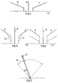
- FIGS. 4 to 6 show the speed ratios as a function of the swivel angle of the control levers assigned to them. 4 is based on a deck switch which has two control levers. A first control lever allows you to switch a certain direction of travel and set a certain engine speed. Another control lever allows the setting of a specific target trolling speed.
- the control lever can be used to preselect a specific direction of travel and a specific engine speed.
- the arrangement is such that the setpoint setting for a trolling speed is automatically superimposed with priority.
- dashed lines 31 are shown with dashed lines 31. It is advantageous that the speeds are superimposed so that a minimum trolling speed is set at a minimum motor speed. The maximum permitted engine speed in trolling mode is then assigned the maximum possible trolling speed.
- a deck switch which can have either one or two control levers.
- travel mode the direction of travel is switched with one or both control levers and an engine speed is set (solid line).
- trolling mode a control lever can be used to specify the trolling propeller shaft speed (dashed line Lines).
- the electronic control unit 12 or separate engine electronics assign a predetermined engine speed to a preselected trolling speed. This assignment takes place depending on certain operating parameters of the engine or the transmission. These operating parameters are characteristic parameters, such as fuel consumption, the thermal load on the clutch or exhaust emission values.
- control lever 27 or drive switch with which a trolling speed can be set is shown schematically.
- the control lever 27 can be pivoted between two end positions (for example 0% and 100%).
- a sector 29 which adjoins an end position (0%) the control lever 27 can only be pivoted against resistance, for example the force of a compression spring 30, in the sense of a further reduction.
- This measure ensures that a negative adjustment gradient can also be generated when the control lever 27 is in an end position from which a further reduction in the desired trolling speed is actually no longer possible.
- the measure explained above increases the passive safety of the system.
Landscapes
- Engineering & Computer Science (AREA)
- Chemical & Material Sciences (AREA)
- Combustion & Propulsion (AREA)
- Mechanical Engineering (AREA)
- Ocean & Marine Engineering (AREA)
- Radar, Positioning & Navigation (AREA)
- Remote Sensing (AREA)
- Hydraulic Clutches, Magnetic Clutches, Fluid Clutches, And Fluid Joints (AREA)
- Control Of Vehicle Engines Or Engines For Specific Uses (AREA)
- Control Of Transmission Device (AREA)
Applications Claiming Priority (3)
| Application Number | Priority Date | Filing Date | Title |
|---|---|---|---|
| DE4125432 | 1991-08-01 | ||
| DE4125432A DE4125432A1 (de) | 1991-08-01 | 1991-08-01 | Steuersystem zum betreiben einer antriebsanlage eines schiffes |
| PCT/EP1992/001709 WO1993002914A1 (de) | 1991-08-01 | 1992-07-28 | Steuersystem zum betreiben einer antriebsanlage eines schiffes |
Publications (2)
| Publication Number | Publication Date |
|---|---|
| EP0595977A1 EP0595977A1 (de) | 1994-05-11 |
| EP0595977B1 true EP0595977B1 (de) | 1995-10-11 |
Family
ID=6437448
Family Applications (1)
| Application Number | Title | Priority Date | Filing Date |
|---|---|---|---|
| EP92916358A Expired - Lifetime EP0595977B1 (de) | 1991-08-01 | 1992-07-28 | Steuersystem zum betreiben einer antriebsanlage eines schiffes |
Country Status (5)
| Country | Link |
|---|---|
| US (1) | US5474480A (ja) |
| EP (1) | EP0595977B1 (ja) |
| JP (1) | JP3448054B2 (ja) |
| DE (2) | DE4125432A1 (ja) |
| WO (1) | WO1993002914A1 (ja) |
Cited By (2)
| Publication number | Priority date | Publication date | Assignee | Title |
|---|---|---|---|---|
| DE102005001552A1 (de) * | 2005-01-13 | 2006-07-27 | Zf Friedrichshafen Ag | Wasserfahrzeugvortriebssystem zum Betreiben einer Antriebsanlage eines Wasserfahrzeuges |
| DE102008025480B3 (de) * | 2008-05-27 | 2009-12-24 | Robert Bosch Gmbh | Steuereinrichtung und Verfahren zur Beeinflussung der Motordrehzahl sowie des Schlupfgrads einer Kupplung eines Schiffsantriebs |
Families Citing this family (16)
| Publication number | Priority date | Publication date | Assignee | Title |
|---|---|---|---|---|
| FR2729637B1 (fr) * | 1995-01-19 | 1997-04-18 | Semt Pielstick | Dispositif et procede de reglage de la vitesse d'un navire |
| JP3804030B2 (ja) * | 1995-07-05 | 2006-08-02 | ヤマハマリン株式会社 | 船舶推進機 |
| DE60042240D1 (de) * | 1999-09-02 | 2009-07-02 | Yanmar Co Ltd | Hydraulisches steuerverfahren für eine marine vorrichtung zur drehzahluntersetzung und drehzahlumkehr im not-rückwärtsbetrieb |
| CA2306291A1 (en) * | 2000-04-20 | 2001-10-20 | Wayne Ernest Conrad | Method and apparatus for improving the speed and fuel economy ¬hence endurance (range)| of aircraft, surface vessels, sub-surface vessels, missiles and torpedoes and/or altering the acoustic signature of such aircraft, surface vessels, sub-surface vessels, missiles or torpedoes |
| FR2810294B1 (fr) * | 2000-06-20 | 2003-02-07 | Roland Auguste Jean Chardey | Dispositif de securite pour les bateaux de peche |
| DE10048103C2 (de) * | 2000-09-28 | 2002-09-05 | Mtu Friedrichshafen Gmbh | Regelsystem für einen Schiffsantrieb |
| US7377827B1 (en) * | 2003-06-20 | 2008-05-27 | Sturdy Corporation | Marine propulsion shift control |
| JP2007509292A (ja) * | 2003-10-20 | 2007-04-12 | ノーティテック プロプライエタリー リミテッド | 特に船舶用のデカップリングクラッチ |
| WO2005102836A1 (en) * | 2004-04-22 | 2005-11-03 | Nautitech Pty Ltd | Decoupler |
| JP4641312B2 (ja) * | 2007-07-06 | 2011-03-02 | 三菱電機株式会社 | 船舶駆動用電子制御装置 |
| JP6062095B1 (ja) * | 2016-06-09 | 2017-01-18 | 株式会社マリタイムイノベーションジャパン | 船舶推進機関用指示装置 |
| IT201700015579A1 (it) * | 2017-02-13 | 2018-08-13 | As Service Srl | Sistema integrato di propulsione per imbarcazioni |
| EP3823894A1 (en) * | 2018-07-19 | 2021-05-26 | ZF Friedrichshafen AG | Method to operate a marine propulsion system in a trolling mode, control unit and marine propulsion system |
| US11215128B1 (en) * | 2018-08-14 | 2022-01-04 | Brunswick Corporation | Acceleration control method for marine engine |
| WO2020110280A1 (ja) * | 2018-11-30 | 2020-06-04 | 本田技研工業株式会社 | 船舶用エンジン回転数制御装置 |
| DE102019211756B3 (de) * | 2019-08-06 | 2020-12-24 | Zf Friedrichshafen Ag | Verfahren, Steuergerät und Computerprogrammprodukt zum Betätigen einer Reibkupplung eines Antriebsstranges eines motorbetriebenen Wasserfahrzeugs |
Family Cites Families (5)
| Publication number | Priority date | Publication date | Assignee | Title |
|---|---|---|---|---|
| US2925156A (en) * | 1957-12-24 | 1960-02-16 | Gen Motors Corp | Drive control mechanism for prime mover with fluid actuated clutches |
| DE2558577A1 (de) * | 1975-12-24 | 1977-09-01 | Hanseatische Konstruktions Ges | Wasserfahrzeug |
| JPS52137890A (en) * | 1976-05-12 | 1977-11-17 | Nippon Air Brake Co | Remote control device for marine main engine |
| SE457873C (sv) * | 1987-04-30 | 1993-08-16 | Styr Kontrollteknik I Stockhol | Manoeversystem foer sjoefarkoster |
| US4836809A (en) * | 1988-03-11 | 1989-06-06 | Twin Disc, Incorporated | Control means for marine propulsion system |
-
1991
- 1991-08-01 DE DE4125432A patent/DE4125432A1/de not_active Withdrawn
-
1992
- 1992-07-28 DE DE59204009T patent/DE59204009D1/de not_active Expired - Lifetime
- 1992-07-28 US US08/182,141 patent/US5474480A/en not_active Expired - Lifetime
- 1992-07-28 WO PCT/EP1992/001709 patent/WO1993002914A1/de not_active Ceased
- 1992-07-28 EP EP92916358A patent/EP0595977B1/de not_active Expired - Lifetime
- 1992-07-28 JP JP50324193A patent/JP3448054B2/ja not_active Expired - Fee Related
Cited By (3)
| Publication number | Priority date | Publication date | Assignee | Title |
|---|---|---|---|---|
| DE102005001552A1 (de) * | 2005-01-13 | 2006-07-27 | Zf Friedrichshafen Ag | Wasserfahrzeugvortriebssystem zum Betreiben einer Antriebsanlage eines Wasserfahrzeuges |
| DE102005001552B4 (de) * | 2005-01-13 | 2010-04-01 | Zf Friedrichshafen Ag | Wasserfahrzeugvortriebssystem zum Betreiben einer Antriebsanlage eines Wasserfahrzeuges |
| DE102008025480B3 (de) * | 2008-05-27 | 2009-12-24 | Robert Bosch Gmbh | Steuereinrichtung und Verfahren zur Beeinflussung der Motordrehzahl sowie des Schlupfgrads einer Kupplung eines Schiffsantriebs |
Also Published As
| Publication number | Publication date |
|---|---|
| JP3448054B2 (ja) | 2003-09-16 |
| US5474480A (en) | 1995-12-12 |
| JPH06509295A (ja) | 1994-10-20 |
| WO1993002914A1 (de) | 1993-02-18 |
| DE4125432A1 (de) | 1993-02-04 |
| DE59204009D1 (de) | 1995-11-16 |
| EP0595977A1 (de) | 1994-05-11 |
Similar Documents
| Publication | Publication Date | Title |
|---|---|---|
| EP0595977B1 (de) | Steuersystem zum betreiben einer antriebsanlage eines schiffes | |
| DE3907841C2 (ja) | ||
| DE3222054C2 (ja) | ||
| EP2193073B1 (de) | Verfahren zur steuerung eines oberflächenantriebs für ein wasserfahrzeug im oberen geschwindigkeitsbereich | |
| DE3636953C2 (ja) | ||
| DE10012122A1 (de) | Kupplungssteuersystem | |
| DE2328112B2 (de) | Regeleinrichtung fuer die brennstoffzufuhr und fuer das uebersetzungsverhaeltnis eines antriebes fuer kraftfahrzeuge | |
| DE69113447T2 (de) | Schiffswende- und untersetzungsgetriebe. | |
| EP0524992B1 (de) | Steuersystem zum betreiben einer antriebsanlage eines schiffes | |
| DE69302797T2 (de) | Steuervorrichtung für ein automatisiertes Getriebe eines Nutzfahrzeuges | |
| DE2844116A1 (de) | Hydromechanisches getriebe zur stufenlosen veraenderung des verhaeltnisses der drehgeschwindigkeiten einer eingangs- und einer ausgangswelle und zur umkehrung der drehrichtung der ausgangswelle | |
| DE2637345C2 (de) | Steuereinrichtung für einen schwenkbaren Schubkrafterzeuger, z.B. Ruderpropeller, von Schiffen | |
| DE69523075T2 (de) | Motorisch angetriebenes system zum lenken eines fahrzeugs | |
| DE60013292T2 (de) | Schaltsynchronisation die ein abfallendes Drehmoment berücksichtigt | |
| DE4112192A1 (de) | Steuersystem zum betreiben einer antriebsanlage eines schiffes | |
| DE4019687C2 (de) | Schiffsantrieb mit Trolling-Einrichtung | |
| DE3425757A1 (de) | Synchronisiertes mechanisch-hydrostatisches getriebe | |
| DE60012507T2 (de) | Automatische servovorrichtung für ein sequentielles getriebe und für eine kupplung | |
| EP1107908B1 (de) | Verfahren zur steuerung eines lastschaltbaren mehrgang-schiffsgetriebes | |
| DE3334724A1 (de) | Einrichtung zur automatischen oder teilautomatischen steuerung eines motors und einer kupplung eines kraftfahrzeuges | |
| DE19861303A1 (de) | Stufengetriebe und Verfahren zum Auslegen eines Ganges eines Stufengetriebes | |
| DE2056521A1 (de) | Zahnräderwechselgetriebe in Gruppenbauart für Kraftfahrzeuge, insbesondere für Acker- und Straßenschlepper | |
| EP1661781B1 (de) | Verfahren zum Erkennen der Drehrichtung der Sekundärseite einer Anfahrkupplung | |
| DE102008025480B3 (de) | Steuereinrichtung und Verfahren zur Beeinflussung der Motordrehzahl sowie des Schlupfgrads einer Kupplung eines Schiffsantriebs | |
| DE2501391A1 (de) | Doppelschrauben-z antrieb fuer einen schlepper |
Legal Events
| Date | Code | Title | Description |
|---|---|---|---|
| PUAI | Public reference made under article 153(3) epc to a published international application that has entered the european phase |
Free format text: ORIGINAL CODE: 0009012 |
|
| 17P | Request for examination filed |
Effective date: 19931123 |
|
| AK | Designated contracting states |
Kind code of ref document: A1 Designated state(s): BE DE FR GB IT |
|
| 17Q | First examination report despatched |
Effective date: 19940912 |
|
| ITF | It: translation for a ep patent filed | ||
| GRAA | (expected) grant |
Free format text: ORIGINAL CODE: 0009210 |
|
| AK | Designated contracting states |
Kind code of ref document: B1 Designated state(s): BE DE FR GB IT |
|
| GBT | Gb: translation of ep patent filed (gb section 77(6)(a)/1977) |
Effective date: 19951016 |
|
| REF | Corresponds to: |
Ref document number: 59204009 Country of ref document: DE Date of ref document: 19951116 |
|
| ET | Fr: translation filed | ||
| PLBQ | Unpublished change to opponent data |
Free format text: ORIGINAL CODE: EPIDOS OPPO |
|
| PLBI | Opposition filed |
Free format text: ORIGINAL CODE: 0009260 |
|
| PLBF | Reply of patent proprietor to notice(s) of opposition |
Free format text: ORIGINAL CODE: EPIDOS OBSO |
|
| 26 | Opposition filed |
Opponent name: RENK AKTIENGESELLSCHAFT Effective date: 19960709 |
|
| PLBF | Reply of patent proprietor to notice(s) of opposition |
Free format text: ORIGINAL CODE: EPIDOS OBSO |
|
| PLBF | Reply of patent proprietor to notice(s) of opposition |
Free format text: ORIGINAL CODE: EPIDOS OBSO |
|
| PLBO | Opposition rejected |
Free format text: ORIGINAL CODE: EPIDOS REJO |
|
| PLBN | Opposition rejected |
Free format text: ORIGINAL CODE: 0009273 |
|
| 27O | Opposition rejected |
Effective date: 19970810 |
|
| REG | Reference to a national code |
Ref country code: GB Ref legal event code: IF02 |
|
| PGFP | Annual fee paid to national office [announced via postgrant information from national office to epo] |
Ref country code: FR Payment date: 20060719 Year of fee payment: 15 |
|
| PGFP | Annual fee paid to national office [announced via postgrant information from national office to epo] |
Ref country code: GB Payment date: 20060726 Year of fee payment: 15 |
|
| GBPC | Gb: european patent ceased through non-payment of renewal fee |
Effective date: 20070728 |
|
| PG25 | Lapsed in a contracting state [announced via postgrant information from national office to epo] |
Ref country code: GB Free format text: LAPSE BECAUSE OF NON-PAYMENT OF DUE FEES Effective date: 20070728 |
|
| REG | Reference to a national code |
Ref country code: FR Ref legal event code: ST Effective date: 20080331 |
|
| PG25 | Lapsed in a contracting state [announced via postgrant information from national office to epo] |
Ref country code: FR Free format text: LAPSE BECAUSE OF NON-PAYMENT OF DUE FEES Effective date: 20070731 |
|
| PGFP | Annual fee paid to national office [announced via postgrant information from national office to epo] |
Ref country code: IT Payment date: 20100724 Year of fee payment: 19 Ref country code: DE Payment date: 20100721 Year of fee payment: 19 |
|
| PGFP | Annual fee paid to national office [announced via postgrant information from national office to epo] |
Ref country code: BE Payment date: 20100714 Year of fee payment: 19 |
|
| BERE | Be: lapsed |
Owner name: *ZF FRIEDRICHSHAFEN A.G. Effective date: 20110731 |
|
| PG25 | Lapsed in a contracting state [announced via postgrant information from national office to epo] |
Ref country code: BE Free format text: LAPSE BECAUSE OF NON-PAYMENT OF DUE FEES Effective date: 20110731 Ref country code: DE Free format text: LAPSE BECAUSE OF NON-PAYMENT OF DUE FEES Effective date: 20120201 |
|
| REG | Reference to a national code |
Ref country code: DE Ref legal event code: R119 Ref document number: 59204009 Country of ref document: DE Effective date: 20120201 |
|
| PG25 | Lapsed in a contracting state [announced via postgrant information from national office to epo] |
Ref country code: IT Free format text: LAPSE BECAUSE OF NON-PAYMENT OF DUE FEES Effective date: 20110728 |