EP0596332B1 - Dispositif de nettoyage de grandes quantités d'eau de déchets - Google Patents
Dispositif de nettoyage de grandes quantités d'eau de déchets Download PDFInfo
- Publication number
- EP0596332B1 EP0596332B1 EP93117013A EP93117013A EP0596332B1 EP 0596332 B1 EP0596332 B1 EP 0596332B1 EP 93117013 A EP93117013 A EP 93117013A EP 93117013 A EP93117013 A EP 93117013A EP 0596332 B1 EP0596332 B1 EP 0596332B1
- Authority
- EP
- European Patent Office
- Prior art keywords
- conveyor
- separation area
- water
- takeover
- screenings
- Prior art date
- Legal status (The legal status is an assumption and is not a legal conclusion. Google has not performed a legal analysis and makes no representation as to the accuracy of the status listed.)
- Expired - Lifetime
Links
Images


Classifications
-
- C—CHEMISTRY; METALLURGY
- C02—TREATMENT OF WATER, WASTE WATER, SEWAGE, OR SLUDGE
- C02F—TREATMENT OF WATER, WASTE WATER, SEWAGE, OR SLUDGE
- C02F1/00—Treatment of water, waste water, or sewage
- C02F1/40—Devices for separating or removing fatty or oily substances or similar floating material
-
- E—FIXED CONSTRUCTIONS
- E02—HYDRAULIC ENGINEERING; FOUNDATIONS; SOIL SHIFTING
- E02B—HYDRAULIC ENGINEERING
- E02B8/00—Details of barrages or weirs ; Energy dissipating devices carried by lock or dry-dock gates
- E02B8/02—Sediment base gates; Sand sluices; Structures for retaining arresting waterborne material
- E02B8/023—Arresting devices for waterborne materials
- E02B8/026—Cleaning devices
-
- B—PERFORMING OPERATIONS; TRANSPORTING
- B01—PHYSICAL OR CHEMICAL PROCESSES OR APPARATUS IN GENERAL
- B01D—SEPARATION
- B01D29/00—Filters with filtering elements stationary during filtration, e.g. pressure or suction filters, not covered by groups B01D24/00 - B01D27/00; Filtering elements therefor
- B01D29/01—Filters with filtering elements stationary during filtration, e.g. pressure or suction filters, not covered by groups B01D24/00 - B01D27/00; Filtering elements therefor with flat filtering elements
- B01D29/03—Filters with filtering elements stationary during filtration, e.g. pressure or suction filters, not covered by groups B01D24/00 - B01D27/00; Filtering elements therefor with flat filtering elements self-supporting
- B01D29/035—Filters with filtering elements stationary during filtration, e.g. pressure or suction filters, not covered by groups B01D24/00 - B01D27/00; Filtering elements therefor with flat filtering elements self-supporting with curved filtering elements
-
- B—PERFORMING OPERATIONS; TRANSPORTING
- B01—PHYSICAL OR CHEMICAL PROCESSES OR APPARATUS IN GENERAL
- B01D—SEPARATION
- B01D29/00—Filters with filtering elements stationary during filtration, e.g. pressure or suction filters, not covered by groups B01D24/00 - B01D27/00; Filtering elements therefor
- B01D29/44—Edge filtering elements, i.e. using contiguous impervious surfaces
- B01D29/445—Bar screens
-
- B—PERFORMING OPERATIONS; TRANSPORTING
- B01—PHYSICAL OR CHEMICAL PROCESSES OR APPARATUS IN GENERAL
- B01D—SEPARATION
- B01D29/00—Filters with filtering elements stationary during filtration, e.g. pressure or suction filters, not covered by groups B01D24/00 - B01D27/00; Filtering elements therefor
- B01D29/62—Regenerating the filter material in the filter
- B01D29/64—Regenerating the filter material in the filter by scrapers, brushes, nozzles, or the like, acting on the cake side of the filtering element
- B01D29/6469—Regenerating the filter material in the filter by scrapers, brushes, nozzles, or the like, acting on the cake side of the filtering element scrapers
- B01D29/6476—Regenerating the filter material in the filter by scrapers, brushes, nozzles, or the like, acting on the cake side of the filtering element scrapers with a rotary movement with respect to the filtering element
-
- E—FIXED CONSTRUCTIONS
- E02—HYDRAULIC ENGINEERING; FOUNDATIONS; SOIL SHIFTING
- E02B—HYDRAULIC ENGINEERING
- E02B15/00—Cleaning or keeping clear the surface of open water; Apparatus therefor
- E02B15/04—Devices for cleaning or keeping clear the surface of open water from oil or like floating materials by separating or removing these materials
- E02B15/10—Devices for removing the material from the surface
- E02B15/104—Conveyors; Paddle wheels; Endless belts
-
- C—CHEMISTRY; METALLURGY
- C02—TREATMENT OF WATER, WASTE WATER, SEWAGE, OR SLUDGE
- C02F—TREATMENT OF WATER, WASTE WATER, SEWAGE, OR SLUDGE
- C02F2103/00—Nature of the water, waste water, sewage or sludge to be treated
- C02F2103/007—Contaminated open waterways, rivers, lakes or ponds
Definitions
- the invention relates to a device for cleaning large amounts of water from screenings at overflow edges, with the features specified in the preamble of claim 1.
- a device for cleaning large amounts of water from screenings at overflow edges with the features specified in the preamble of claim 1.
- B. cooling water to be removed in large quantities from a river an overflow edge is usually created and the overflowing water is removed.
- this should be free of screenings up to floating suspended matter.
- the task of sieving large amounts of water arises especially when and after the occurrence of a large rain event, for example a thunderstorm. A considerable amount of water then accumulates in a relatively short time, and the sewage treatment plant is not designed to cope with it.
- Rain retention basins and rain overflow basins are used here to temporarily store the large amount of water and to process it specifically after the end of the rain event. But also such rain retention basins only have a limited absorption capacity, which is rarely exceeded, so that the excess water then accumulated unexplained z. B. is directed into a river. Especially in such thunderstorms and especially after periods of dry weather, the amount of water that comes with it entails a large amount of dirt that needs to be separated.
- a device of the type described above is known from DE-A-40 37 884.
- the separating surface is designed as a piece of a cylinder jacket and is arranged with an axis lying parallel to the overflow edge.
- the separating surface extends over approximately 90 ° of the cylinder jacket, and the axis of the cylinder jacket is provided about the radius of the cylinder jacket lower than the overflow edge, so that the water flowing over the overflow edge approximately at the highest point of the cylinder jacket is fed.
- the separation area is thus limited in terms of area, and there is a risk that after clogging of the separation area, the water will flow over the device unpurified and into an outlet channel which runs across the overflow edge in the direction of flow.
- a transfer unit driven around the axis of the cylinder jacket, is assigned to the separation surface for the removal of the screenings deposited on the separation surface.
- the transfer unit is driven by the overflowing water itself, so that the drive is dependent on the water level above the overflow edge. If the water level is low, there is a risk that the transfer unit will no longer be driven. If the water level is high, there is a risk that the separating area, which is limited in area, will quickly clog and the further water will flow over unpurified.
- the invention has for its object to provide a device of the type described above with which large amounts of water can be reliably cleaned without the risk that the separation surface clogs.
- the separating surface is arranged with its axis approximately at the height of the overflow edge and extends in an arc upwards or downwards over approximately 180 ° of the lying cylinder jacket, so that a forced flow through the separating surface takes place, and in that a transverse conveyor device for the lateral removal of the separated screenings is provided.
- the separation surface in the form of a piece of a cylinder jacket is arranged with the axis of the cylinder jacket at approximately the same height as the overflow edge, so that there is the possibility of also using the enlarged separation area.
- There is a forced flow ie the incoming liquid must be passed through the separating surface. If the driven transfer unit fails, the water level rises and a further area of the separation area that is not clogged is made available. At most, the water level rises here. In this respect, there is the possibility of providing an intermittent drive for the takeover unit and controlling it, for example, as a function of a rising water level.
- a cross conveyor is provided for the lateral removal of the separated screenings, so that the direction of flow of the water does not have to be changed.
- the cross conveyor device has the task of taking over the screenings from the take-over unit and conveying them sideways.
- a screw conveyor device with housing, conveyor helix and drive can be provided as the cross conveyor device.
- the axis of the screw conveyor device in turn extends parallel to the axis of the cylinder section of the separating device and parallel to the overflow edge.
- the screenings are conveyed away via the cross conveyor and can e.g. B. dropped into a container.
- the separating surface can consist of several rake bars arranged parallel to one another.
- a comb-like rake penetrating the rake bars can be provided as the assigned take-over unit.
- the separating surface is thus formed on a rake from rake bars, the rake bars being arranged along circumferential lines of the cylinder and extending over part of the Extend circumference in each case.
- the separating surface is cleaned with each pass of the comb-like rake.
- the distance between the rake bars is decisive for the degree of separation. With relatively large amounts of water, the screenings are separated out in the sense of a rough cleaning of the water.
- the separating surface may consist of a sieve wall and for a feed spiral to be provided as the take-over unit.
- the conveyor spiral then sweeps along the circumference along the screen wall and takes the separated screenings with it.
- the formation of a separating surface on a sieve wall also allows finer sieving to be carried out, that is to say comparatively smaller screenings can be removed from the water.
- the geometry of the holes or slots in the screen wall is decisive for the separated screenings.
- the conveyor helix together with the sieve wall can simultaneously form the cross conveyor.
- the separating surface on a rake is realized as a piece of a cylinder jacket, the separating surface can be provided on the outside or inside of the rake bars. In the case of deposition on the outside, the rake bars extend in an arc upward and then downward again after the overflow edge. If the separating surface is realized on the inside, the rake bars extend from the separating edge in an arc downwards, from where they rise again, to form a trough for the separated screenings.
- the separation surface and the take-over unit can be assigned a transfer device which is comb-shaped and the rulers interspersed.
- This transfer device has the task of taking over the screenings from the receiving unit and guiding them into the downstream cross conveyor.
- the transfer device itself is arranged so as to be movable in order to transfer the screenings which are temporarily stored into the cross conveyor and thus to be cleaned again in order to be able to derive screenings when the takeover unit passes through again.
- the transfer device is expediently pivoted outside the scope of the transfer unit and has a stop for a cam arranged on the shaft of the transfer unit. This advantageously ensures that the transfer device is cyclically moved and cleaned by the drive of the transfer unit.
- the transfer device is mounted above the cross conveyor and extends with its comb-like tines into the circumferential path of the transfer unit.
- the takeover unit is designed as a screw conveyor device, the housing of which functions as a sieve wall, this device also forms the transverse conveyor device.
- the screw conveyor can then merge into an upward conveyor line to z. B. enable or facilitate the dropping of the screenings into a container.
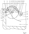
- an overflow edge 2 is formed, over which the large amount of water 3 to be screened flows according to arrow 4.
- the amount of water 3 comes, for example, from a retention basin, a river or the like.
- An overflow basin 5 adjoins the overflow edge 2 or the wall 1, into which only purified water passes, which can be removed from there or passed on.
- the new device is shown relative to the overflow edge 2 with its essential, basic parts.
- the rake bars 6 have extensions 9 facing the overflow edge 2, with which they are placed on the overflow edge 2. The attachment of the device at the place of use is otherwise not shown.
- the rake bars 6, the number and spacing of which can be chosen constructively next to one another, that is to say in the direction of the axis 8, form on their outside a separating surface 10 which begins at the overflow edge 2 and extends in an arc upwards. It can be seen that the separating surface 10 can expand with the amount of water 3 above the overflow edge 2. This ensures that the separating surface 10 adapts itself automatically to the amount of water or is available for different amounts of water.
- the rake bars 6 are fixed in place.
- a transfer unit 11 is assigned to the rake bars 6 and the separating surface 10 formed by them, in detail has a shaft 12 and arms 13 projecting radially thereon. Fingers 14 are attached to the arms 13, their geometry and arrangement being matched to the arrangement of the rake bars 6. The fingers 14 reach through the spaces between the rake bars 6 and extend to a certain extent beyond the outer circumference of the cylinder jacket 7 or the separating surface 10.
- the shaft 12 or the take-over unit 11 is driven continuously or in cycles according to arrow 15 by a drive (not shown), for example an electric motor, the fingers 14 of the take-over unit 11 entering the spaces between the rake bars 6 in the region of the overflow edge 2 and that transport screenings separated on the separation surface 10 with upwards.
- the screenings then come out of the area of the water quantity 3 and fall over the downwardly curved part of the screen rods 6 into a cross conveyor 16, which can have a housing 17 open at the top, a driven shaft 18 and a conveyor spiral 19. It is understood that the shaft 18 is driven in rotation by a drive, not shown, so that the thrown off screenings are conveyed away to the side. With the exception of the separation surface 10, through which water flows, the separated screenings are located above an indicated line of attack 20 and thus outside the water. It can be seen that the absorption capacity of the overflow basin 5 is limited by the height of the overflow edge 2, so that the cleaned water must be removed from this basin or discharged. When storing, the overflow basin 5 is to be made correspondingly large.
- the device can have a transfer device 21.
- the transfer device 21 has, as an essential component, a comb-shaped rake 22, the individual fingers or rods of which likewise reach through the spaces between the rake rods 6.
- the fingers or sticks are around one horizontal axis 23 is pivotally supported to a limited extent and extends from the outside into the interior of the cylinder jacket 7, the rake bars 6 being penetrated.
- the one end position of the transfer device 21 is shown, which is secured for example by a stop, not shown.
- the fingers or rods of the transfer device 21 have a stop 24 on their underside in the interior of the device, the downward-facing surface of which cooperates with a cam 25 which is arranged on the shaft 12 in a rotationally fixed manner.
- a cam 25 which is arranged on the shaft 12 in a rotationally fixed manner.
- the transfer device 21 serves to transport the screenings over the upper edge 26 of the housing 17 of the cross conveyor 16.
- An advantage of the transfer device 21 is therefore that the cross conveyor 16 can be arranged relatively high. If the cross conveyor 16 is arranged relative to the cylinder jacket 7 in the lower part, the transfer device 21 can generally also be omitted. Otherwise, the transfer device 21 has the task of ensuring that no separated screenings get back into the cleaned water of the overflow basin 5.
- Figure 2 shows a further embodiment of the device, which is basically similar to the device of Figure 1, so that reference can be made to the relevant description.
- the rake bars 6 are different from the embodiment according to FIG. 1, but not fixed in the upper area of the cylinder jacket 7, but in the lower area so that the separating surface 10 is formed on the inside of the rake bars 6.
- the takeover unit 11 can be configured identically to the exemplary embodiment in FIG. 1.
- the fingers 14 can be curved in the direction shown. Also one straight, radial extension of the fingers 14 is possible.
- the fingers 14 protrude relatively further beyond the separating surface 10 in the radial direction, so that a corresponding amount of screenings can be transported upwards from the fingers 14 when the fingers 14 come out of the area of the screen bars 6 and the line of attack 20 of water quantity 3 emerge upwards.
- the transfer device 21 is shown in dashed lines in its starting position in solid lines and in its swung-open position.
- the dashed position is achieved by pivoting over the cam 25 and the stop 24 in the direction of arrow 27.
- the transferred screenings then slide according to arrow 28 into the cross conveyor 16. It goes without saying that a conveyor belt could also be provided as the cross conveyor 16.
- the embodiment which is indicated in FIG. 3 represents a structural union of the separating surface, the take-over unit 11 and the transverse conveyor device 16.
- the separating surface 10 is formed as the inner surface of a sieve wall 29, which also extends over part of the circumference of a cylinder jacket 7.
- the sieve wall 29 is open towards the amount of water 3 and adjoins the overflow edge 2 with an extension 9.
- the sieve wall 29 has openings, for example holes or slots, the geometry and arrangement of which is matched to the fineness of the screenings to be separated.
- the separating surface 10 formed in this way is assigned the take-over unit 11 in the form of a conveying helix 30, which is preferably mounted without a shaft in the housing-like sieve wall 29 and is driven accordingly.
- the outer edge of the conveyor helix 30 repeatedly sweeps along the screen wall 29 and in particular along the separating surface 10, so that the screenings are grasped and conveyed sideways in the direction of the axis 8.
- the device can continue in an upward conveying path 31, in the housing 32 of which a shaft 34 with a conveying helix 35 driven by a motor 33 is provided.
- the shaft 34 can be connected to a universal joint 36 and a shaft stub 37, which carries and drives the shaft which is shaftless over a large part of its length.
- a flap 38 can be provided so that the screenings can be removed and conveyed away at this point. As a rule, however, the screenings are conveyed upwards via the conveyor section 31 and dropped into a container 40 via a chute 39.
Landscapes
- Chemical & Material Sciences (AREA)
- Engineering & Computer Science (AREA)
- Chemical Kinetics & Catalysis (AREA)
- General Engineering & Computer Science (AREA)
- Mechanical Engineering (AREA)
- Civil Engineering (AREA)
- Structural Engineering (AREA)
- Environmental & Geological Engineering (AREA)
- Analytical Chemistry (AREA)
- Life Sciences & Earth Sciences (AREA)
- Hydrology & Water Resources (AREA)
- Water Supply & Treatment (AREA)
- Organic Chemistry (AREA)
- Separation Of Solids By Using Liquids Or Pneumatic Power (AREA)
- Filtration Of Liquid (AREA)
- Cyclones (AREA)
- Drilling And Exploitation, And Mining Machines And Methods (AREA)
- Structure Of Belt Conveyors (AREA)
- Sewage (AREA)
Claims (10)
- Dispositif d'épuration de grandes quantités d'eau (3) de matières retenues par une grille, sur des bords de déversoir (2), en particulier provenant de bassins d'eaux pluviales, de rivières ou similaires, avec une surface de séparation (10) fixe, traversée par la quantité d'eau, qui est configurée en tant que partie d'une enveloppe cylindrique (7) avec axe (8) parallèle au bord de déversoir (2), à la surface de séparation (10) étant associée une unité de reprise (11) entraînée autour de l'axe (8) de l'enveloppe cylindrique (7), pour l'enlèvement des matières retenues par la grille, séparées sur la surface de séparation (10), caractérisé en ce que la surface de séparation (10) avec l'axe (8) se situe à peu près à hauteur du bord de déversoir (2) et s'étend en arc vers le haut ou vers le bas sur environ 180° de l'enveloppe cylindrique (7) horizontale, de sorte qu'il se produit un écoulement forcé à travers la surface de séparation (10) et en ce qu'il est prévu un dispositif de transport transversal (16) pour l'évacuation latérale des matières retenues par la grille, séparées.
- Dispositif selon la revendication 1, caractérisé en ce que la surface de séparation (10) est constituée de plusieurs barreaux de grille (6) parallèles entre eux et en tant qu'unité de reprise (11) il est prévu un râteau (22) en peigne traversant les barreaux de grille (6).
- Dispositif selon la revendication 1, caractérisé en ce que la surface de séparation (10) est constituée d'une paroi de tamis (29) et en ce que comme unité de reprise (11) il est prévu une hélice de transport (30).
- Dispositif selon la revendication 3, caractérisé en ce que l'hélice de transport (30) constitue conjointement avec la paroi de tamis (29), en même temps, le dispositif de transport transversal (16).
- Dispositif selon la revendication 4, caractérisé en ce que le dispositif de transport transversal (16) comporte un dispositif de transport à vis sans fin avec carter (17), hélice de transport (19) et entraînement.
- Dispositif selon la revendication 1 ou 2, caractérisé en ce que la surface de séparation (10) est prévue à l'extérieur ou à l'intérieur sur les barreaux de grille (6).
- Dispositif selon la revendication 6, caractérisé en ce qu'à la surface de séparation (10) et à l'unité de reprise (11) est associé un dispositif de transfert (21), qui est configuré en peigne et traverse les barreaux de grille (6).
- Dispositif selon la revendication 7, caractérisé en ce que le dispositif de transfert (21) est monté pivotant à l'extérieur de la périphérie de l'unité de reprise (11) et présente une butée (24) pour une came (25) placée sur l'arbre (12) de l'unité de reprise (11).
- Dispositif selon les revendications 7 et 8, caractérisé en ce que le dispositif de transfert (21) est monté au-dessus du dispositif de transport transversal (16).
- Dispositif selon la revendication 3, caractérisé en ce que la vis de transport sans fin se prolonge par un parcours de transport (31) dirigé vers le haut.
Applications Claiming Priority (2)
| Application Number | Priority Date | Filing Date | Title |
|---|---|---|---|
| DE4237123 | 1992-11-03 | ||
| DE4237123A DE4237123C2 (de) | 1992-11-03 | 1992-11-03 | Vorrichtung zum Reinigen großer Wassermengen von Rechengut |
Publications (2)
| Publication Number | Publication Date |
|---|---|
| EP0596332A1 EP0596332A1 (fr) | 1994-05-11 |
| EP0596332B1 true EP0596332B1 (fr) | 1996-05-15 |
Family
ID=6472009
Family Applications (1)
| Application Number | Title | Priority Date | Filing Date |
|---|---|---|---|
| EP93117013A Expired - Lifetime EP0596332B1 (fr) | 1992-11-03 | 1993-10-21 | Dispositif de nettoyage de grandes quantités d'eau de déchets |
Country Status (10)
| Country | Link |
|---|---|
| US (1) | US5422000A (fr) |
| EP (1) | EP0596332B1 (fr) |
| JP (1) | JP3479330B2 (fr) |
| KR (1) | KR100296938B1 (fr) |
| CN (1) | CN1052285C (fr) |
| AT (1) | ATE138141T1 (fr) |
| CZ (1) | CZ232393A3 (fr) |
| DE (2) | DE4237123C2 (fr) |
| PL (1) | PL172986B1 (fr) |
| RU (1) | RU2117735C1 (fr) |
Families Citing this family (18)
| Publication number | Priority date | Publication date | Assignee | Title |
|---|---|---|---|---|
| DE19517101C1 (de) * | 1995-05-10 | 1996-12-05 | Huber Hans Gmbh Maschinen Und | Vorrichtung zum Entfernen von Abscheidegut aus einer überlaufenden Flüssigkeit |
| KR20010002905A (ko) * | 1999-06-18 | 2001-01-15 | 배수현 | 하천 이물질 수거장치 |
| GB2370999A (en) * | 2001-01-11 | 2002-07-17 | Mono Pumps Ltd | A screening device with a rotating cleaning member |
| EP1223252A3 (fr) * | 2001-01-11 | 2002-12-18 | Mono Pumps Limited | Dispositif de filtration |
| DE10158612A1 (de) * | 2001-11-29 | 2003-06-12 | Kurt Zeuner | Feststoffrückhaltevorrichtung für Entlastungsbauwerke der Mischkanalisation |
| CN1294339C (zh) * | 2003-06-12 | 2007-01-10 | 上海隧道工程股份有限公司 | 铰接式螺旋输送机 |
| US7310130B2 (en) * | 2004-10-05 | 2007-12-18 | Asml Netherlands B.V. | Lithographic apparatus and position measuring method |
| RU2374399C1 (ru) * | 2008-03-04 | 2009-11-27 | Евгений Владимирович Левин | Устройство для очистки воды от мусора |
| CN102677634B (zh) * | 2011-03-17 | 2014-09-03 | 哈尔滨盛迪电力设备有限公司 | 水电站库区进水口拦污栅清淤装置 |
| PT3003526T (pt) * | 2013-06-03 | 2019-04-23 | Aqseptence Group Pty Ltd | Peneira de correia contínua |
| CN103613149B (zh) * | 2013-11-26 | 2016-07-06 | 刘晓静 | 一种水轮旋转格栅 |
| CN104030456B (zh) * | 2014-05-21 | 2015-12-09 | 湖北大学 | 一种水力驱动型生物滤坝净水系统 |
| CN106567364B (zh) * | 2016-10-20 | 2018-08-24 | 湖南省汇杰勘测设计股份有限公司 | 一种可自动净化水质的环保水坝 |
| KR101959509B1 (ko) * | 2018-07-26 | 2019-03-18 | (주)랜드로드 | 빗물 배수구 오염물질 여과장치 및 이의 모니터링 시스템 |
| TR2021011306A1 (tr) * | 2021-07-11 | 2023-01-23 | İzmi̇r Yüksek Teknoloji̇ Ensti̇tüsü Rektörlüğü | Otonom coanda ti̇pi̇ su alma yapisi |
| CN113529675B (zh) * | 2021-08-04 | 2023-05-12 | 潘守成 | 一种水利工程用水面垃圾收集装置 |
| DE102022111102A1 (de) | 2022-05-05 | 2023-11-09 | Oliver Kraus | Separationsanlage zum Entfernen von Feststoffen aus Abwasser |
| CN116024943B (zh) * | 2023-02-16 | 2024-01-02 | 甘肃省水利水电勘测设计研究院有限责任公司 | 一种具有污物拦截的水库大坝用水源调度分流装置 |
Family Cites Families (44)
| Publication number | Priority date | Publication date | Assignee | Title |
|---|---|---|---|---|
| US546708A (en) * | 1895-09-24 | Walter s | ||
| DE148021C (fr) * | ||||
| DE212048C (fr) * | ||||
| US184815A (en) * | 1876-11-28 | Improvement in apparatus for treating substances with hydrocarbon | ||
| US493403A (en) * | 1893-03-14 | holmes | ||
| GB191306172A (en) * | 1913-03-12 | 1914-02-19 | Frederick William Jones | Improvements in or connected with Screening Apparatus and the like for the Treatment of Sewage and other purposes. |
| US1143496A (en) * | 1914-08-04 | 1915-06-15 | Larkin Briles | Automatic cleaner for fish-screens. |
| CH190659A (fr) * | 1936-02-15 | 1937-05-15 | Aine Jonneret Fils | Dispositif pour l'épuration des eaux en excès de canalisations. |
| US2776755A (en) * | 1951-02-14 | 1957-01-08 | Wittemann Company Inc | Apparatus for straining liquids |
| US2830695A (en) * | 1955-12-16 | 1958-04-15 | Marion H Fennimore | Flexible screw conveyor |
| US2910181A (en) * | 1956-07-02 | 1959-10-27 | Passavant Werke | Combined rake and crushing system |
| US2929504A (en) * | 1958-05-19 | 1960-03-22 | Chain Belt Co | Waste-flow screening apparatus |
| US3255074A (en) * | 1964-04-03 | 1966-06-07 | Beloit Corp | Headbox for paper-making machine |
| US3559667A (en) * | 1968-12-11 | 1971-02-02 | Gen Motors Corp | Governor |
| DE6812487U (de) * | 1968-12-18 | 1969-06-26 | Atlas Mak Maschb Gmbh Fa | Vorrichtung zur selbsttaetigen rechengutablage |
| DE2142540A1 (de) * | 1971-08-25 | 1973-03-01 | Benno Reiche | Rechenreiniger |
| DE2460355C3 (de) * | 1974-12-20 | 1978-11-09 | Maschinenfabrik Hellmut Geiger Gmbh & Co Kg, 7500 Karlsruhe | Antrieb für Hubvorrichtungen mit zeitweise auftretender mechanischer Überlastung |
| GB1525871A (en) * | 1977-01-24 | 1978-09-20 | Longwood Eng Co Ltd | Scraper device for the rakes or the like of mechanically cleaned screens and a screen embodying such a scraper |
| US4153557A (en) * | 1978-01-30 | 1979-05-08 | Mitsutaka Hori | Bar screen |
| DE2944047A1 (de) * | 1979-10-31 | 1981-06-11 | Passavant-Werke Michelbacher Hütte, 6209 Aarbergen | Reinigungsvorrichtung fuer bogenrechen |
| US4424129A (en) * | 1982-06-28 | 1984-01-03 | Bunger Richard E | Dewatering apparatus for waste recovery systems |
| US4415462A (en) * | 1982-08-12 | 1983-11-15 | Finch Harvey E | Self-cleaning screen |
| CH660854A5 (de) * | 1983-06-01 | 1987-05-29 | Arag Apparatebau | Vorrichtung zum ausscheiden von grobgut aus einem fliessfaehigen medium. |
| DE3322578C2 (de) * | 1983-06-14 | 1986-01-16 | Sulzer-Escher Wyss GmbH, 7980 Ravensburg | Sortiervorrichtung |
| US4713179A (en) * | 1986-03-14 | 1987-12-15 | Goedderz Sr Stanley J | Removable culvert grate |
| CH667483A5 (de) * | 1986-10-17 | 1988-10-14 | Werner Nill | Vorrichtung zur reinigung eines siebes oder rechens in einer abwasseranlage. |
| DE3716434C1 (de) * | 1987-05-16 | 1988-12-08 | Hans-Georg Huber | Vorrichtung zum Entfernen von Rechen- und/oder Siebgut aus in einem Gerinne stroemender Fluessigkeit |
| DE8707094U1 (de) * | 1987-05-16 | 1987-09-03 | Bionik GmbH Innovative Technik für die Umwelt, 6200 Wiesbaden | Vorrichtung zum Abscheiden mechanischer Verunreinigungen aus strömenden Flüssigkeiten |
| SE458862B (sv) * | 1988-03-18 | 1989-05-16 | Ola Mileson | Anordning foer separering och transport av material |
| SU1605964A1 (ru) * | 1988-06-13 | 1990-11-15 | Украинский научно-исследовательский институт механизации и электрификации сельского хозяйства | Устройство дл отделени крупных включений навоза |
| DE3820212A1 (de) * | 1988-06-14 | 1989-12-21 | Heinz Dipl Ing Deiters | Bogenrechen mit ueberkopf ladendem rechenreiniger fuer klaeranlagen |
| JP2600302B2 (ja) * | 1988-06-29 | 1997-04-16 | 三菱樹脂株式会社 | 雨水浸透桝 |
| DE3910389C1 (fr) * | 1989-03-31 | 1990-08-30 | Hans-Georg Dipl.-Ing. 8434 Berching De Huber | |
| SU1663135A1 (ru) * | 1989-06-08 | 1991-07-15 | Ленинградский инженерно-строительный институт | Ливнеспуск |
| US5006236A (en) * | 1989-09-25 | 1991-04-09 | Hallco Fabricators, Inc. | Contaminant entrained flow separating apparatus |
| US5110461A (en) * | 1990-09-05 | 1992-05-05 | Abel Guenther | Apparatus for separating liquids and solids |
| JPH0661412B2 (ja) * | 1990-03-12 | 1994-08-17 | 清庵工業株式会社 | オーバーフロー式濾過機 |
| DE9113761U1 (de) * | 1990-11-05 | 1992-09-10 | Klasnic, Branko, Dipl.-Ing., 81925 München | Gerät für die mechanische Reinigung von schmutzbehafteten Flüssigkeiten |
| JPH0684637B2 (ja) * | 1990-11-07 | 1994-10-26 | 錦一郎 増尾 | ごみ取り桝を接続した雨水排水路 |
| FI87186C (fi) * | 1990-11-19 | 1992-12-10 | Ekotuotanto Ab Oy | Skruvgaller |
| DE4037844C2 (de) * | 1990-11-28 | 1999-06-02 | Grohe Armaturen Friedrich | Verbindungselement an einer Zugknopf-Ablaufgarnitur |
| DE4037884A1 (de) * | 1990-11-28 | 1992-06-04 | Hartl Thomas Dominik | Rechen-reinigungsanlage |
| DE9205674U1 (de) * | 1991-04-25 | 1992-07-23 | Klasnic, Branko, 8000 München | Gerät für die mechanische Reinigung von Flüssigkeiten in Gerinnen oder in Behältern |
| US5232587A (en) * | 1992-03-02 | 1993-08-03 | Tom Hegemier | Stormwater inlet filter |
-
1992
- 1992-11-03 DE DE4237123A patent/DE4237123C2/de not_active Expired - Fee Related
-
1993
- 1993-10-21 AT AT93117013T patent/ATE138141T1/de not_active IP Right Cessation
- 1993-10-21 EP EP93117013A patent/EP0596332B1/fr not_active Expired - Lifetime
- 1993-10-21 DE DE59302596T patent/DE59302596D1/de not_active Expired - Fee Related
- 1993-10-28 KR KR1019930022638A patent/KR100296938B1/ko not_active Expired - Fee Related
- 1993-10-29 PL PL93300894A patent/PL172986B1/pl not_active IP Right Cessation
- 1993-10-29 US US08/145,394 patent/US5422000A/en not_active Expired - Lifetime
- 1993-11-02 JP JP27458493A patent/JP3479330B2/ja not_active Expired - Fee Related
- 1993-11-02 CZ CZ932323A patent/CZ232393A3/cs unknown
- 1993-11-03 CN CN93119699A patent/CN1052285C/zh not_active Expired - Fee Related
- 1993-11-04 RU RU93050123A patent/RU2117735C1/ru active
Also Published As
| Publication number | Publication date |
|---|---|
| JPH06200511A (ja) | 1994-07-19 |
| KR940011365A (ko) | 1994-06-21 |
| CN1087152A (zh) | 1994-05-25 |
| CZ232393A3 (en) | 1994-05-18 |
| EP0596332A1 (fr) | 1994-05-11 |
| DE59302596D1 (de) | 1996-06-20 |
| RU2117735C1 (ru) | 1998-08-20 |
| DE4237123C2 (de) | 1995-02-16 |
| PL300894A1 (en) | 1994-05-16 |
| KR100296938B1 (ko) | 2001-10-22 |
| JP3479330B2 (ja) | 2003-12-15 |
| US5422000A (en) | 1995-06-06 |
| PL172986B1 (pl) | 1998-01-30 |
| CN1052285C (zh) | 2000-05-10 |
| DE4237123A1 (de) | 1994-05-05 |
| ATE138141T1 (de) | 1996-06-15 |
Similar Documents
| Publication | Publication Date | Title |
|---|---|---|
| EP0596332B1 (fr) | Dispositif de nettoyage de grandes quantités d'eau de déchets | |
| EP0163158B1 (fr) | Dispositif pour enlever des matériaux flottants d'un liquide coulant dans un égout | |
| EP0259547B1 (fr) | Dispositif pour éliminer des produits solides d'un liquide coulant dans une rigole | |
| DE3019127C2 (de) | Vorrichtung zum Entfernen von Rechengut aus Zulaufgerinnen, insbesondere von Kläranlagen | |
| DE19524276C2 (de) | Vorrichtung zum Entfernen von Abscheidegut aus in einem Gerinne strömender Flüssigkeit | |
| DE4239083A1 (fr) | ||
| EP1759753A2 (fr) | Système de filtration | |
| EP1476275B1 (fr) | Dispositif de reception et separation de copeaux et de liquide tombant de machines-outils (debordement) | |
| DE2640803A1 (de) | Lamellenseparator zur sedimentierung (gravitationsseparation) | |
| DE4328476C2 (de) | Vorrichtung zum Austragen von festen Bestandteilen aus einem Fluid | |
| DE3920196C2 (fr) | ||
| EP0722760A1 (fr) | Filtre à arêtes pour liquides | |
| WO1994004276A1 (fr) | Convoyeur pour agregats produits lors du traitement de beton residuel | |
| DE4006970A1 (de) | Vorrichtung zur reinigung von abwasser | |
| DE2512291C2 (de) | Vorrichtung zum Abscheiden von Öl aus einem Öl-Wasser-Gemisch | |
| DE2263549C3 (de) | Vorrichtung zum Auswaschen von Verunreinigungen aus körnigen Feststoffen | |
| DE102009012829A1 (de) | Vorrichtung zum Klassieren, Fördern und Entwässern von Sand | |
| DE3328700A1 (de) | Vorrichtung zum ausscheiden von grobgut aus einem fliessfaehigen medium | |
| DE4235903A1 (de) | Vorrichtung zum Entfernen von Abscheidegut aus einer in einem Gerinne strömender Flüssigkeit | |
| DE9303867U1 (de) | Reinigungsvorrichtung zur Reinigung von in einem Gerinne fließendem Wasser | |
| EP0554740B1 (fr) | Pompe d'entraînement avec dispositif de criblage | |
| DE3109947C2 (de) | Drehtrommelfilter | |
| DE9205674U1 (de) | Gerät für die mechanische Reinigung von Flüssigkeiten in Gerinnen oder in Behältern | |
| DE4308333A1 (de) | Reinigungsvorrichtung zur Reinigung von in einem Gerinne fließendem Wasser | |
| EP0709525A1 (fr) | Grille pour un déversoir d'eau pluviale |
Legal Events
| Date | Code | Title | Description |
|---|---|---|---|
| PUAI | Public reference made under article 153(3) epc to a published international application that has entered the european phase |
Free format text: ORIGINAL CODE: 0009012 |
|
| AK | Designated contracting states |
Kind code of ref document: A1 Designated state(s): AT BE DE ES FR GB IT NL PT SE |
|
| 17P | Request for examination filed |
Effective date: 19940402 |
|
| 17Q | First examination report despatched |
Effective date: 19950720 |
|
| GRAH | Despatch of communication of intention to grant a patent |
Free format text: ORIGINAL CODE: EPIDOS IGRA |
|
| ITF | It: translation for a ep patent filed | ||
| GRAA | (expected) grant |
Free format text: ORIGINAL CODE: 0009210 |
|
| AK | Designated contracting states |
Kind code of ref document: B1 Designated state(s): AT BE DE ES FR GB IT NL PT SE |
|
| PG25 | Lapsed in a contracting state [announced via postgrant information from national office to epo] |
Ref country code: NL Free format text: LAPSE BECAUSE OF FAILURE TO SUBMIT A TRANSLATION OF THE DESCRIPTION OR TO PAY THE FEE WITHIN THE PRESCRIBED TIME-LIMIT Effective date: 19960515 Ref country code: ES Free format text: THE PATENT HAS BEEN ANNULLED BY A DECISION OF A NATIONAL AUTHORITY Effective date: 19960515 Ref country code: BE Effective date: 19960515 |
|
| REF | Corresponds to: |
Ref document number: 138141 Country of ref document: AT Date of ref document: 19960615 Kind code of ref document: T |
|
| REF | Corresponds to: |
Ref document number: 59302596 Country of ref document: DE Date of ref document: 19960620 |
|
| ET | Fr: translation filed | ||
| GBT | Gb: translation of ep patent filed (gb section 77(6)(a)/1977) |
Effective date: 19960530 |
|
| PG25 | Lapsed in a contracting state [announced via postgrant information from national office to epo] |
Ref country code: SE Effective date: 19960815 |
|
| PG25 | Lapsed in a contracting state [announced via postgrant information from national office to epo] |
Ref country code: PT Effective date: 19960816 |
|
| NLV1 | Nl: lapsed or annulled due to failure to fulfill the requirements of art. 29p and 29m of the patents act | ||
| PLBQ | Unpublished change to opponent data |
Free format text: ORIGINAL CODE: EPIDOS OPPO |
|
| PLBI | Opposition filed |
Free format text: ORIGINAL CODE: 0009260 |
|
| PLBF | Reply of patent proprietor to notice(s) of opposition |
Free format text: ORIGINAL CODE: EPIDOS OBSO |
|
| 26 | Opposition filed |
Opponent name: HERCULES DESIGN & DEVELOPMENT LTD. Effective date: 19970217 |
|
| PLBF | Reply of patent proprietor to notice(s) of opposition |
Free format text: ORIGINAL CODE: EPIDOS OBSO |
|
| PG25 | Lapsed in a contracting state [announced via postgrant information from national office to epo] |
Ref country code: DE Effective date: 19970701 |
|
| PLBO | Opposition rejected |
Free format text: ORIGINAL CODE: EPIDOS REJO |
|
| PLBN | Opposition rejected |
Free format text: ORIGINAL CODE: 0009273 |
|
| STAA | Information on the status of an ep patent application or granted ep patent |
Free format text: STATUS: OPPOSITION REJECTED |
|
| 27O | Opposition rejected |
Effective date: 19990205 |
|
| REG | Reference to a national code |
Ref country code: GB Ref legal event code: 772N Free format text: COUNTERCLAIM FOR REVOCATION LODGED WITH THE PATENTS COURT ON 8 MARCH 2000 (HC-99-04996) |
|
| REG | Reference to a national code |
Ref country code: GB Ref legal event code: 772M Free format text: COUNTERCLAIM FOR REVOCATION WITHDRAWN BY CONSENT ORDER DATED 3 MAY 2001. |
|
| REG | Reference to a national code |
Ref country code: GB Ref legal event code: IF02 |
|
| PGFP | Annual fee paid to national office [announced via postgrant information from national office to epo] |
Ref country code: FR Payment date: 20051019 Year of fee payment: 13 |
|
| REG | Reference to a national code |
Ref country code: GB Ref legal event code: 732E |
|
| REG | Reference to a national code |
Ref country code: FR Ref legal event code: ST Effective date: 20070629 |
|
| PG25 | Lapsed in a contracting state [announced via postgrant information from national office to epo] |
Ref country code: FR Free format text: LAPSE BECAUSE OF NON-PAYMENT OF DUE FEES Effective date: 20061031 |
|
| PGFP | Annual fee paid to national office [announced via postgrant information from national office to epo] |
Ref country code: AT Payment date: 20081028 Year of fee payment: 16 |
|
| PGFP | Annual fee paid to national office [announced via postgrant information from national office to epo] |
Ref country code: IT Payment date: 20091023 Year of fee payment: 17 |
|
| PG25 | Lapsed in a contracting state [announced via postgrant information from national office to epo] |
Ref country code: AT Free format text: LAPSE BECAUSE OF NON-PAYMENT OF DUE FEES Effective date: 20091021 |
|
| PG25 | Lapsed in a contracting state [announced via postgrant information from national office to epo] |
Ref country code: IT Free format text: LAPSE BECAUSE OF NON-PAYMENT OF DUE FEES Effective date: 20101021 |
|
| PGFP | Annual fee paid to national office [announced via postgrant information from national office to epo] |
Ref country code: GB Payment date: 20120315 Year of fee payment: 19 |
|
| GBPC | Gb: european patent ceased through non-payment of renewal fee |
Effective date: 20121021 |
|
| PG25 | Lapsed in a contracting state [announced via postgrant information from national office to epo] |
Ref country code: GB Free format text: LAPSE BECAUSE OF NON-PAYMENT OF DUE FEES Effective date: 20121021 |