EP0596535A2 - High-resolution measuring method for linear and rotary positions - Google Patents
High-resolution measuring method for linear and rotary positions Download PDFInfo
- Publication number
- EP0596535A2 EP0596535A2 EP93118089A EP93118089A EP0596535A2 EP 0596535 A2 EP0596535 A2 EP 0596535A2 EP 93118089 A EP93118089 A EP 93118089A EP 93118089 A EP93118089 A EP 93118089A EP 0596535 A2 EP0596535 A2 EP 0596535A2
- Authority
- EP
- European Patent Office
- Prior art keywords
- scale
- sensor
- period
- output signal
- sensor elements
- Prior art date
- Legal status (The legal status is an assumption and is not a legal conclusion. Google has not performed a legal analysis and makes no representation as to the accuracy of the status listed.)
- Granted
Links
- 238000000034 method Methods 0.000 title claims abstract description 33
- 238000005259 measurement Methods 0.000 claims abstract description 12
- 230000003287 optical effect Effects 0.000 claims description 2
- 230000005693 optoelectronics Effects 0.000 claims 1
- 230000000737 periodic effect Effects 0.000 abstract description 7
- 238000005516 engineering process Methods 0.000 abstract description 2
- 239000004065 semiconductor Substances 0.000 abstract description 2
- 238000012545 processing Methods 0.000 description 3
- 238000012935 Averaging Methods 0.000 description 2
- 230000007423 decrease Effects 0.000 description 2
- 230000000694 effects Effects 0.000 description 2
- 238000011156 evaluation Methods 0.000 description 2
- 230000005415 magnetization Effects 0.000 description 2
- 230000005540 biological transmission Effects 0.000 description 1
- 230000015572 biosynthetic process Effects 0.000 description 1
- 238000006073 displacement reaction Methods 0.000 description 1
- 238000011089 mechanical engineering Methods 0.000 description 1
- 230000035945 sensitivity Effects 0.000 description 1
Images
Classifications
-
- G—PHYSICS
- G01—MEASURING; TESTING
- G01D—MEASURING NOT SPECIALLY ADAPTED FOR A SPECIFIC VARIABLE; ARRANGEMENTS FOR MEASURING TWO OR MORE VARIABLES NOT COVERED IN A SINGLE OTHER SUBCLASS; TARIFF METERING APPARATUS; MEASURING OR TESTING NOT OTHERWISE PROVIDED FOR
- G01D5/00—Mechanical means for transferring the output of a sensing member; Means for converting the output of a sensing member to another variable where the form or nature of the sensing member does not constrain the means for converting; Transducers not specially adapted for a specific variable
- G01D5/12—Mechanical means for transferring the output of a sensing member; Means for converting the output of a sensing member to another variable where the form or nature of the sensing member does not constrain the means for converting; Transducers not specially adapted for a specific variable using electric or magnetic means
- G01D5/14—Mechanical means for transferring the output of a sensing member; Means for converting the output of a sensing member to another variable where the form or nature of the sensing member does not constrain the means for converting; Transducers not specially adapted for a specific variable using electric or magnetic means influencing the magnitude of a current or voltage
- G01D5/142—Mechanical means for transferring the output of a sensing member; Means for converting the output of a sensing member to another variable where the form or nature of the sensing member does not constrain the means for converting; Transducers not specially adapted for a specific variable using electric or magnetic means influencing the magnitude of a current or voltage using Hall-effect devices
-
- G—PHYSICS
- G01—MEASURING; TESTING
- G01B—MEASURING LENGTH, THICKNESS OR SIMILAR LINEAR DIMENSIONS; MEASURING ANGLES; MEASURING AREAS; MEASURING IRREGULARITIES OF SURFACES OR CONTOURS
- G01B7/00—Measuring arrangements characterised by the use of electric or magnetic techniques
- G01B7/02—Measuring arrangements characterised by the use of electric or magnetic techniques for measuring length, width or thickness
-
- G—PHYSICS
- G01—MEASURING; TESTING
- G01D—MEASURING NOT SPECIALLY ADAPTED FOR A SPECIFIC VARIABLE; ARRANGEMENTS FOR MEASURING TWO OR MORE VARIABLES NOT COVERED IN A SINGLE OTHER SUBCLASS; TARIFF METERING APPARATUS; MEASURING OR TESTING NOT OTHERWISE PROVIDED FOR
- G01D5/00—Mechanical means for transferring the output of a sensing member; Means for converting the output of a sensing member to another variable where the form or nature of the sensing member does not constrain the means for converting; Transducers not specially adapted for a specific variable
- G01D5/12—Mechanical means for transferring the output of a sensing member; Means for converting the output of a sensing member to another variable where the form or nature of the sensing member does not constrain the means for converting; Transducers not specially adapted for a specific variable using electric or magnetic means
- G01D5/244—Mechanical means for transferring the output of a sensing member; Means for converting the output of a sensing member to another variable where the form or nature of the sensing member does not constrain the means for converting; Transducers not specially adapted for a specific variable using electric or magnetic means influencing characteristics of pulses or pulse trains; generating pulses or pulse trains
- G01D5/24428—Error prevention
- G01D5/24433—Error prevention by mechanical means
- G01D5/24438—Special design of the sensing element or scale
-
- G—PHYSICS
- G01—MEASURING; TESTING
- G01D—MEASURING NOT SPECIALLY ADAPTED FOR A SPECIFIC VARIABLE; ARRANGEMENTS FOR MEASURING TWO OR MORE VARIABLES NOT COVERED IN A SINGLE OTHER SUBCLASS; TARIFF METERING APPARATUS; MEASURING OR TESTING NOT OTHERWISE PROVIDED FOR
- G01D5/00—Mechanical means for transferring the output of a sensing member; Means for converting the output of a sensing member to another variable where the form or nature of the sensing member does not constrain the means for converting; Transducers not specially adapted for a specific variable
- G01D5/12—Mechanical means for transferring the output of a sensing member; Means for converting the output of a sensing member to another variable where the form or nature of the sensing member does not constrain the means for converting; Transducers not specially adapted for a specific variable using electric or magnetic means
- G01D5/244—Mechanical means for transferring the output of a sensing member; Means for converting the output of a sensing member to another variable where the form or nature of the sensing member does not constrain the means for converting; Transducers not specially adapted for a specific variable using electric or magnetic means influencing characteristics of pulses or pulse trains; generating pulses or pulse trains
- G01D5/24471—Error correction
- G01D5/24476—Signal processing
Definitions
- the invention relates to a method for position measurement with a periodic scale and, on the other hand, a longitudinally movable sensor which for the precise determination of distances and positions in a straight line or on curved, for. B. circular lines.
- Such measurements are increasingly required in mechanical engineering, in precision engineering or in the technology of semiconductor components.
- the method according to the invention uses a sensor arrangement which has a significantly smaller structural dimension than the scale.
- the sensor period length which is possible with the reduced structural dimensions and is considerably reduced compared to the scale period length, is a prerequisite for the fact that the proposed method can work with a significantly higher resolution of the length compared to the scale period length. This enables the use of larger scale period lengths. With a longer period, the requirement for the adjustment of the sensor compared to the scale is much lower for purely geometrical reasons. Therefore, there is no decrease in the degree of interpolation for reasons of adjustment.
- firstly signal differences are formed and secondly further evaluations are carried out essentially with the zero crossings of these differences. This compensates for the temperature and distance dependencies of the signals, which would otherwise lead to errors.
- sensors are used which have a large number of individual sensors which average the output signal present at a specific location in the period over a number of periods. This allows higher scale tolerances.
- the large usable scale period is also a prerequisite for the very low processing speed requirements at high travel speeds between the scale and the sensor.
- a temperature drift of the zero point of the voltage divider output signals is avoided by using the same magnetoresistive layer strips in a nested arrangement and so it is ensured with the magnetic measuring arrangement that the signal differences necessary for further processing are immediately available at the output of the sensor arrangement without any effort for their formation must be driven.
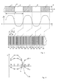
- FIG. 1 shows the schematic representation of a periodically structured scale, the basic periodic course of a physical quantity in the vicinity of the scale and a measurement of the spatial distribution of this physical quantity.
- 2 shows measured values as obtained from the measuring arrangement in the position shown in FIG. 1.
- 3 shows a scale in its starting position and the same scale shifted by a certain distance with respect to the sensor arrangement and serves to explain the position measurement in three stages.
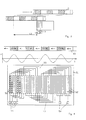
- 4 shows a magnetic scale and a magnetoresistive sensor arrangement suitable for carrying out a length measurement.
- the scale is built up alternately in the longitudinal direction from areas 1 and areas 2.
- the period length p of the scale is given by the sum of the two lengths of the areas 1 and 2.
- the areas 1 and 2 have the effect that in the vicinity of the scale surface a physical quantity E above the location has a periodic course.
- This physical quantity E can be, for example, a magnetic field which is caused by magnetization of regions 1 and 2 in the opposite direction, or a light intensity which arises when passing through a scale with regions 1 and 2 of different light transmission.
- the curve shape of the periodic course of the physical quantity E as a function of the position x is not fixed to specific functions (such as the sine function). All that is required is a continuous course of the function E (x).
- the sensor arrangement which arises from a multiplicity of regions 7, is located in the immediate vicinity of the scale, specifically in such a way that the scale surface and the sensor arrangement surface face each other in parallel. In the figure, the two parts mentioned are shown side by side for the sake of clarity.
- the sensor arrangement is divided into sections 7 of equal length.
- the length of each section corresponds to half the scale period length p / 2.
- the position of the individual sensor elements 10-15, 20-25, 30-35 etc. is completely the same.
- the distance a of all individual sensor elements is the same.
- six individual sensor elements 10-15, 20-25, 30-35 etc. are present in each section 7.
- the starting point of the scale is marked with S.
- the sensor arrangement is shifted by the distance V with respect to this initial value S.
- Each individual sensor element 10-15, 20-25, 30-35 etc. gives an output signal A, e.g. in the form of a voltage or a current, which is proportional to the value of the physical quantity E in place. All individual sensor elements 10-15, 20-25, 30-35 etc. have the same sensitivity.
- the output signals A of the individual sensor elements 10-15 are shown as curve 3 for the position shown in FIG. 1 in FIG. 2.
- the output signals A of the individual sensor elements 20-25 represent curve 4.
- differences in the output signals A of the individual sensor elements are formed, each offset by half a scale period length p / 2, that is, between the individual sensor elements 10 and 20, 11 and 21, 12 and 22, etc. These individual sensor elements thus form the sensor element pairs S 0, S 1, S 3 etc.
- the output signals of the sensor element pairs S 0, S 1, S 3 etc. are shown in FIG. 2 as curve 5.
- Curve 5 has the advantage over curves 3 and 4, which represent the course of the physical quantity in the first and second section 7 of the sensor arrangement, that it is zero-symmetrical with regard to its deflection and that its zero crossing 6 from the location of the first individual sensor element 10 is accurate the offset V is removed. A shift can therefore always be read from the position of the zero crossing.
- the zero crossing 6 of the output signal differences 5 is therefore used to quantitatively determine the magnitude of the shift in the scale relative to the sensor arrangement.
- the zero crossing 6 lies between the sensor pairs S 3 and S 4.
- Fig. 3 it is shown that the scale is shifted from the sensor arrangement by a distance which is more than a whole scale period length p.
- the output signal of the first pair of sensor elements S 0 and the output signal of the pair of sensor elements S 3 offset by a quarter of the period length p are continuously measured during the shift. From these two signals, the number ni of the whole scale periods p is determined using customary incremental counting methods. Forward and backward movements are recognized from the two signals in the known methods.
- the signal averaging is provided by adding further individual sensor elements offset by an entire scale period p over a plurality of period lengths p, but this is not shown in FIG. 1 for the sake of clarity.
- the signal averaging makes the measurement signals much more precise, so that a high degree of interpolation is made possible, which is the prerequisite for a high length resolution.
- FIG. 1 A special embodiment of the method with a magnetic scale and magnetoresistive sensor arrangement is shown in FIG.
- the magnetic track 50 of the scale is drawn smaller than the sensor chip 51 in the width direction. Values in the mm range are provided both for the magnetic track width 50 and for the width of the sensor chip 51.
- the magnetic track 51 has magnetized areas at regular intervals in the positive and negative directions. A periodic magnetic field H (x) is thus present.
- Magnetoresistive layer strips 52 are arranged on the chip 51 as individual sensor elements at a uniform distance. The layer strips 52 all carry the same barber pole structures 56 with the same angle. There are four layer strips 52 per half-scale period.
- the layer strips 52 are connected in series by connecting lines 53.
- the resistance values of the magnetoresistive layer strips 52 are proportional to the magnetic field at their location. In this way, the output signal differences 5 averaged over four scale periods are immediately obtained at the outputs of the voltage dividers 55, without any evaluation circuit being necessary in this case.
- the further processing of the output signal differences 5 to determine the displacement of the scale relative to the sensor arrangement then corresponds to the above.
Landscapes
- Physics & Mathematics (AREA)
- General Physics & Mathematics (AREA)
- Engineering & Computer Science (AREA)
- Signal Processing (AREA)
- Transmission And Conversion Of Sensor Element Output (AREA)
- Testing, Inspecting, Measuring Of Stereoscopic Televisions And Televisions (AREA)
- Optical Transform (AREA)
- Length Measuring Devices By Optical Means (AREA)
- Length Measuring Devices With Unspecified Measuring Means (AREA)
- Analysing Materials By The Use Of Radiation (AREA)
Abstract
Description
Die Erfindung betrifft ein Verfahren zur Positionsmessung mit einem periodischen Maßstab und einem dagegen in Längsrichtung beweglichen Sensor, das zur präzisen Ermittlung von Abständen und Positionen in gerader Linie oder auf gekrümmten, z. B. kreisförmigen Linien, dient. Solche Messungen werden in zunehmendem Maße im Maschinenbau, in der Feinwerktechnik oder in der Technologie der Halbleiterbauelemente erforderlich.The invention relates to a method for position measurement with a periodic scale and, on the other hand, a longitudinally movable sensor which for the precise determination of distances and positions in a straight line or on curved, for. B. circular lines. Such measurements are increasingly required in mechanical engineering, in precision engineering or in the technology of semiconductor components.
Verfahren zur Längenmessung mit periodisch strukturiertem Maßstab und dagegen beweglichem Sensor sind allgemein bekannt. Um jedoch mit den bekannten Verfahren eine höhere Auflösung zu erreichen, ist es erforderlich, die Periodenlänge des Maßstabes herabzusetzen, um bei gleichem Interpolationsgrad auf die angestrebte minimale nachweisbare Länge zu kommen. Dem steht bei magnetischen Längenmeßanordnungen grundsätzlich die Tatsache entgegen, daß das Magnetfeld eines periodisch magnetisierten Maßstabes mit dem Abstand von der Maßstabsoberfläche sehr stark abnimmt und in einem Abstand, der der Periodenlänge etwa entspricht, kaum noch nachweisbar ist. Die Justierung des Sensors gegenüber dem Maßstab im Mikrometerabstand ist technisch nur mit dem höchsten Aufwand realisierbar. Gegen die Erhöhung des Interpolationsgrades spricht gerade bei kleinen Periodenlängen die Meßungenauigkeit, die sich aus der starken Abstandsabhängigkeit des Magnetfeldes ergibt. Auch bei optischen Meßsystemen wachst bei der notwendigen Verkleinerung der Periodenlängen der Justieraufwand überproportional aus einfachen geometrischen Gründen an. Jede Fehljustierung, besonders in der Parallelität der Maßstabsgitterstreifen zu den Sensorgitterstreifen, führt zu einem Verlust an Signalhöhe, so daß der gleiche Interpolationsgrad bei Verkleinerung der Maßstabsperiode praktisch nicht gehalten werden kann.Methods for length measurement with a periodically structured scale and, on the other hand, a movable sensor are generally known. However, in order to achieve a higher resolution with the known methods, it is necessary to reduce the period length of the scale in order to achieve the desired minimum detectable length with the same degree of interpolation. This is fundamentally opposed to the fact that the magnetic field of a periodically magnetized scale decreases very strongly with the distance from the surface of the scale and is hardly detectable at a distance which corresponds approximately to the period length. The adjustment of the sensor in relation to the scale at a micrometer distance can only be achieved technically with the greatest effort. The inaccuracy of the measurement, which results from the strong dependence on the distance of the magnetic field, speaks against the increase in the degree of interpolation, especially in the case of small period lengths. Even with optical measuring systems, the adjustment effort increases disproportionately for simple geometric reasons when the period lengths are reduced. Any misalignment, especially in the parallelism of the scale grating strips to the sensor grid strips, leads to a loss of signal level, so that the same degree of interpolation can practically not be maintained if the scale period is reduced.
Ein Vorschlag, wie mit magnetischen Maßstäben und magnetoresistiven Sensoren bessere Längenauflösungen erreicht werden können, liegt mit der Offenlegungsschrift DE 33 25 353 vor. Hier werden n nebeneinanderliegende Magnetspuren verwendet, über denen sich auch n Sensoren parallel nebeneinander befinden. Die Magnetspuren sind in ihrem periodischen Magnetisierungsmuster gleich, die Perioden sind aber um den Bruchteil der Periode, der sich bei ihrer Division durch n ergibt, gegenüber versetzt. Die Auflösung, die sich damit realisieren läßt, ist um einen Faktor n besser, als die mit einer einfachen Einspuranordnung erreichbare.A proposal as to how better length resolutions can be achieved with magnetic scales and magnetoresistive sensors is available in the published
Die Schwierigkeiten, die sich bei dieser Anordnung ergeben, liegen einerseits darin, daß die vielen nebeneinanderliegenden Magnetspuren mit ihrem geringen Versatz gegeneinander mit gleicher Amplitude geschrieben werden müssen, was einen äußerst hohen Aufwand an Justiergenauigkeit erfordert. Der gleiche Aufwand ist dann noch einmal bei der Positionierung des Sensors gegenüber dem Maßstab aufzubringen. Dabei muß sowohl der Abstand der Einzelsensoren über der gesamten Breite des Maßstabes mit seinen vielen Spuren als auch der Winkel der Sensoroberfläche zu Maßsstabslängsrichtung hochpräzise eingestellt werden.The difficulties that arise with this arrangement are, on the one hand, that the many magnetic tracks lying next to one another, with their slight offset relative to one another, have to be written with the same amplitude, which requires an extremely high level of adjustment accuracy. The same effort must then be applied again when positioning the sensor relative to the scale. Both the distance of the individual sensors across the entire width of the scale with its many traces and the angle of the sensor surface to the longitudinal direction of the scale must be set with high precision.
Bei dem in den Ansprüchen beschriebenen Verfahren wird zur Längenmessung nur eine Spur eines periodisch strukturierten Maßstabes benutzt. Das erfindungsgemäße Verfahren benutzt eine Sensoranordnung, die gegenüber dem Maßstab eine wesentlich verkleinerte Strukturabmessung aufweist. Die mit den verkleinerten Strukturabmessungen mögliche, gegenüber der Maßstabsperiodenlänge wesentlich verringerte Sensorperiodenlänge ist eine Voraussetzung dafür, daß bei dem vorgeschlagenen Verfahren gegenüber der Maßstabsperiodenlänge mit einer wesentlich höheren Auflösung der Länge gearbeitet werden kann. Das ermöglicht die Verwendung größerer Maßstabsperiodenlängen. Bei größerer Periodenlänge ist die Anforderung an die Justierung des Sensors gegenüber dem Maßstab schon aus rein geometrischen Gründen wesentlich geringer. Deshalb ist eine Abnahme des Interpolationsgrades aus Justiergründen hier nicht vorhanden. Der hohe Interpolationsgrad wird auch dadurch gesichert, daß erstens Signaldifferenzen gebildet werden und zweitens im wesentlichen mit den Nulldurchgängen dieser Differenzen weitere Auswertungen vorgenommen werden. Damit werden Temperatur- und Abstandsabhängigkeiten der Signale kompensiert, die sonst zu Fehlern führen würden. Dazu kommt hier noch, daß Sensoren verwendet werden, bei denen eine Vielzahl von Einzelsensoren vorhanden sind, die das an einem bestimmten Ort der Periode vorhandene Ausgangssignal über mehrere Perioden mitteln. Damit sind höhere Maßstabstoleranzen zulässig.In the method described in the claims, only one track of a periodically structured scale is used for length measurement. The method according to the invention uses a sensor arrangement which has a significantly smaller structural dimension than the scale. The sensor period length, which is possible with the reduced structural dimensions and is considerably reduced compared to the scale period length, is a prerequisite for the fact that the proposed method can work with a significantly higher resolution of the length compared to the scale period length. This enables the use of larger scale period lengths. With a longer period, the requirement for the adjustment of the sensor compared to the scale is much lower for purely geometrical reasons. Therefore, there is no decrease in the degree of interpolation for reasons of adjustment. The high degree of interpolation is also ensured in that firstly signal differences are formed and secondly further evaluations are carried out essentially with the zero crossings of these differences. This compensates for the temperature and distance dependencies of the signals, which would otherwise lead to errors. In addition, sensors are used which have a large number of individual sensors which average the output signal present at a specific location in the period over a number of periods. This allows higher scale tolerances.
Die große verwendbare Maßstabsperiode ist ebenfalls Voraussetzung für die sehr geringe Anforderung an die Verarbeitungsgeschwindigkeit bei hohen Verfahrgeschwindigkeiten zwischen Maßstab und Sensor.The large usable scale period is also a prerequisite for the very low processing speed requirements at high travel speeds between the scale and the sensor.
Auch im Fall der magnetischen Meßanordnung sind Temperatur- und Fremdmagnetfeldeinwirkungen von äußerst geringem Einfluß auf die ermittelte Länge, da die Magnetfelder nur in ihrer relativen Größe zueinander ausgewertet werden und nur Felddifferenzen an Orten des Maßstabes ermittelt werden, die um eine halbe Periodenlänge auseinanderliegen, also bei gleicher Größe entgegengesetztes Vorzeichen haben.Even in the case of the magnetic measuring arrangement, the effects of temperature and external magnetic fields have an extremely small influence on the length determined, since the magnetic fields are only evaluated in their relative size to one another and only field differences at locations on the scale are determined that are half a period apart, i.e. at of the same size have opposite signs.
Eine Temperaturdrift des Nullpunktes der Spannungsteilerausgangssignale wird durch die Verwendung gleicher magnetoresistiver Schichtstreifen in verschachtelter Anordnung vermieden und so ist es bei der magnetischen Meßanordnung gewährleistet, daß sofort am Ausgang der Sensoranordnung die für die Weiterverarbeitung notwendigen Signaldifferenzen zur Verfügung stehen, ohne daß für ihre Bildung irgendein Aufwand getrieben werden muß.A temperature drift of the zero point of the voltage divider output signals is avoided by using the same magnetoresistive layer strips in a nested arrangement and so it is ensured with the magnetic measuring arrangement that the signal differences necessary for further processing are immediately available at the output of the sensor arrangement without any effort for their formation must be driven.
Die Erfindung wird an Ausführungsbeispielen, die weitere Vorteile des Verfahrens deutlich machen, näher erläutert. In den zugehörigen Zeichnungen zeigt Fig. 1 die schematische Darstellung eines periodisch strukturierten Maßstabes, den prinzipiellen periodischen Verlauf einer physikalischen Größe in der Nähe des Maßstabes und eine Messung der Ortsverteilung dieser physikalischen Größe. In Fig. 2 sind Meßwerte, wie sie von der Meßanordnung in der in Fig. 1 gezeigten Lage erhalten wurden, dargestellt. Fig. 3 zeigt einen Maßstab in seiner Ausgangslage sowie denselben Maßstab gegenüber der Sensoranordnung um eine bestimmte Strecke verschoben und dient der Erläuterung der Positionsmesssung in drei Stufen. In Fig. 4 sind ein magnetischer Maßstab und eine zur Durchführung einer Längenmessung geeignete magnetoresistive Sensoranordnung dargestellt.The invention is explained in more detail using exemplary embodiments which make further advantages of the method clear. In the accompanying drawings, FIG. 1 shows the schematic representation of a periodically structured scale, the basic periodic course of a physical quantity in the vicinity of the scale and a measurement of the spatial distribution of this physical quantity. 2 shows measured values as obtained from the measuring arrangement in the position shown in FIG. 1. 3 shows a scale in its starting position and the same scale shifted by a certain distance with respect to the sensor arrangement and serves to explain the position measurement in three stages. 4 shows a magnetic scale and a magnetoresistive sensor arrangement suitable for carrying out a length measurement.
Anhand eines im oberen Teil der Fig. 1 dargestellten Maßstabes und einer im unteren Teil dargestellten Sensoranordnung wird das Verfahren zunächst vom Grundsätzlichen her erläutert. Der Maßstab ist in Längsrichtung abwechselnd aus den Bereichen 1 und den Bereichen 2 aufgebaut. Die Periodenlänge p des Maßstabes ist durch die Summe der beiden Längen der Bereiche 1 und und 2 gegeben. Die Bereiche 1 und 2 bewirken, daß in der Nähe der Maßstabsoberfäche eine physikalische Größe E über dem Ort dargestellt einen periodischen Verlauf hat. Diese physikalische Göße E kann beispielsweise ein Magnetfeld, das durch Auf magnetisierung der Bereiche 1 und 2 in entgegengesetzter Richtung hervorgerufen wird, oder eine Lichtintesität sein, die beim Durchtritt durch einen Maßstab mit Bereichen 1 und 2 von unterschiedlicher Lichtdurchlässigkeit entsteht. Für das erfindungsgemäße Verfahren ist die Kurvenform des periodischen Verlaufs der phsikalischen Größe E in Abhängigkeit von der Position x nicht auf bestimmte Funktionen (wie z.B. die Sinusfunktion) festgelegt. Notwendig ist lediglich ein stetiger Verlauf der Funktion E(x). Bei der Durchführung des Verfahrens befindet sich die Sensoranordnung, die aus einer Vielzahl von Bereichen 7 entsteht, in unmittelbarer Nähe des Maßstabes und zwar so, daß die Maßstabsoberfläche und die Sensoranordnungsoberfläche sich parallel gegenüberstehen. In der Figur sind die beiden genannten Teile der Deutlichkeit halber nebeneinander dargestellt.On the basis of a scale shown in the upper part of FIG. 1 and a sensor arrangement shown in the lower part, the method is first explained in principle. The scale is built up alternately in the longitudinal direction from
Die Sensoranordnung ist in gleichlange Abschnitte 7 aufgeteilt. Die Länge jedes Abschnittes stimmt mit der halben Maßstabsperiodenlänge p/2 überein. In jedem Abschnitt 7 ist die Lage der Einzelsensorelemente 10-15, 20-25, 30-35 usw. völlig gleich. Der Abstand a aller Sensoreinzelelemente ist gleich. Im dargestellten Beispiel sind in jedem Abschnitt 7 sechs Einzelsensorelemente 10-15, 20-25, 30-35 usw. vorhanden. Der Anfangsort des Maßstabes ist mit S gekennzeichnet. Die Sensoranordnung ist gegenüber diesem Anfangswert S um die Strecke V, verschoben.The sensor arrangement is divided into
Jedes Einzelsensorelement 10-15, 20-25, 30-35 usw. gibt ein Ausgangssignal A, z.B. in Form einer Spannung oder eines Stromes, ab, das proportional zu dem Wert der physikalischen Größe E an seinem Ort ist. Alle Einzelsensorelemente 10-15, 20-25, 30-35 usw. haben die gleiche Meßempfindlichkeit.Each individual sensor element 10-15, 20-25, 30-35 etc. gives an output signal A, e.g. in the form of a voltage or a current, which is proportional to the value of the physical quantity E in place. All individual sensor elements 10-15, 20-25, 30-35 etc. have the same sensitivity.
Die Ausgangssignale A der Einzelsensorelemente 10-15 sind für die in Fig. 1 gezeigte Position in Fig. 2 als Kurve 3 dargestellt. Die Ausgangssignale A der Einzelsensorelemente 20-25 gibt Kurve 4 wieder. Erfindungsgemäß werden Differenzen der Ausgangssignale A der Einzelsensorelemente gebildet, die jeweils um eine halbe Maßstabsperiodenlänge p/2 gegeneinander versetzt sind, also zwischen den Einzelsensorelementen 10 und 20, 11 und 21, 12 und 22 usw. Diese Einzelsensorelemente bilden so die Sensorelementepaare S 0, S 1, S 3 usw. Die Ausgangssignale der Sensorelementepaare S 0, S 1, S 3 usw. sind in Fig. 2 als Kurve 5 dargestellt. Die Kurve 5 hat gegenüber den Kurven 3 und 4, die den Verlauf der physikalischen Größe im ersten und zweiten Abschnitt 7 der Sensoranordnung wiedergeben, den Vorteil, daß sie bezüglich ihrer Auslenkung nullsymmetrisch ist und daß ihr Nulldurchgang 6 vom Ort des ersten Einzelsensorelementes 10 genau um den Versatz V, entfernt liegt. Eine Verschiebung kann also stets aus der Lage des Nulldurchgangs abgelesen werden. Äußere Einflüsse auf die Einzelsensorelemente 10-15, 20-25 usw., wie Temperatur oder im Falle magnetischer Sensoren von homogenen Störfeldern, wirken sich auf alle Sensorelemente in gleichem Maße aus und verändern die Signalamplitude. Die Nulldurchgänge der Signale der Sensorpaare S 1 usw. werden aber davon nicht beeinflußt. Ebenso sind Signaländerungen, die aus der Änderung des Abstandes zwischen Maßstab und Sensoranordnung resultieren, wegen ihres gleichen Einflusses auf alle Einzelsensorelemente auf den Nulldurchgang 6 ohne Wirkung.The output signals A of the individual sensor elements 10-15 are shown as curve 3 for the position shown in FIG. 1 in FIG. 2. The output signals A of the individual sensor elements 20-25 represent
Um die Größe der Verschiebung des Maßstabes gegenüber der Sensoranordnung quantitativ zu ermitteln, wird also der Nulldurchgang 6 der Ausgangssignaldifferenzen 5 benutzt. Im dargestellten Beispiel liegt der Nulldurchgang 6 zwischen den Sensorpaaren S 3 und S 4. Damit entspricht der Versatz V, drei (von S 3 abgeleitet) Einzelsensorabständen a (L2 = 3 a) und zusätzlich einem Bruchteil des Einzelsensorabstandes, der durch Interpolation aus den Ausgangssignaldifferenzen von S 3 und S 4 erhalten wird nachThe zero
![]()
![]()
Ist die Verschiebung des Maßstabes gegenüber der Sensoranordnung größer als eine halbe Maßstabsperiodenlänge p/2, so ergibt sich in den Ausgangssignalen der Sensorelementepaare S 0, S 1 usw. ein Nulldurchgang, in dem der Anstieg des Signals über der Sensorposition das umgekehrte Vorzeichen hat, als in Fig. 2 gezeigt. In diesem Fall ist bei der Positionsberechnung eine weitere halbe Maßstabsperiode zu addieren.If the shift in the scale relative to the sensor arrangement is greater than half a scale period length p / 2, the output signals of the sensor element pairs S 0,
In Fig. 3 ist dargestellt, daß der Maßstab gegenüber der Sensoranordnung um eine Stecke verschoben ist, die mehr als eine ganze Maßstabsperiodenlänge p lang ist. Um die Zahl der ganzen Maßstabsperioden zu ermitteln, die in dieser Strekke enthalten ist, wird das Ausgangssignal des ersten Sensorelementenpaares S 0 und das Ausgangssignal des um ein Viertel der Periodenlänge p versetzten Sensorelementepaares S 3 während der Verschiebung ständig gemessen. Aus diesen beiden Signalen wird nach üblichen inkrementalen Zählverfahren die Zahl ni der ganzen Maßstabsperioden p ermittelt. Vor- und Rückwärtsbewegungen werden aus den beiden Signalen in den bekannten Verfahren erkannt. Die Gesamtverschiebung für den in Fig. 3 dargestellten Fall ergibt sich so zu![]()
mit L1 = ni - p und L2 = n2 a und L3 nach der oben angegebenen Beziehung.In Fig. 3 it is shown that the scale is shifted from the sensor arrangement by a distance which is more than a whole scale period length p. In order to determine the number of whole scale periods contained in this range, the output signal of the first pair of sensor elements S 0 and the output signal of the pair of sensor elements S 3 offset by a quarter of the period length p are continuously measured during the shift. From these two signals, the number ni of the whole scale periods p is determined using customary incremental counting methods. Forward and backward movements are recognized from the two signals in the known methods. The total shift for the case shown in FIG. 3 thus results ![]()
with L 1 = ni - p and L 2 = n2 a and L 3 according to the relationship given above.
Für die Durchführung des Verfahrens, soweit es bisher vorgestellt wurde, werden nur die Einzelsensorelemente 10-15 und 20-25 in zwei Abschnitten 7 der Sensoranordnung benötigt, die zusammen die Länge einer Maßstabsperiode p haben. Eine weitere Verbesserung des Verfahrens ist jedoch dadurch möglich, daß die Ausgangssignale aller gleichen Einzelsensorelemente 10-15, 20-25, 30-35 usw., die über viele Abschnitte 7 in gleichem Abstand a angeordnet sind, benutzt werden. So wird das Ausgangssignal des Einzelsensorelements 10 zu dem des um eine ganze Maßstabsperiode versetzt angeordenten 30 addiert, ebenso werden die Signale der Einzelsenssorelemente 20 und 40 zusammengefaßt. Erst mit diesen Summen wird die Ausgangssignaldifferenz 5 gebildet. Dadurch wird eine Mittelung der Signale über zwei Maßstabsperioden p durchgeführt. Gleiches gilt natürlich dann auch für die Einzelsensorelemente 11 und 31 sowie 21 und 41 usw. entsprechend.To carry out the method, as far as it has been presented so far, only the individual sensor elements 10-15 and 20-25 are required in two
Darüber hinaus ist die Singalmittelung durch Hinzunahme weiterer um eine ganze Maßstabsperiode p versetzter Einzelsensorelemente über eine Vielzahl von Periodenlängen p vorgesehen, was in der Fig. 1 der Übersichtlichkeit halber jedoch nicht dargestellt ist. Durch die Signalmittelung werden die Meßsignale wesentlich genauer, so daß ein hoher Interpolationsgrad ermöglicht wird, der die Voraussetzung für eine hohe Längenauflösung ist.In addition, the signal averaging is provided by adding further individual sensor elements offset by an entire scale period p over a plurality of period lengths p, but this is not shown in FIG. 1 for the sake of clarity. The signal averaging makes the measurement signals much more precise, so that a high degree of interpolation is made possible, which is the prerequisite for a high length resolution.
Die Anforderungen an die Positionsgenauigkeit des Maßstabes gegenüber der Sensoranordnung bleiben dabei nach wie vor sehr gering.The requirements for the positional accuracy of the scale compared to the sensor arrangement remain very low.
Eine spezielle Ausführung des Verfahrens mit Magnetmaßstab und magnetoresistiver Sensoranordnung ist in Fig.4 dargestellt. Die Magnetspur 50 des Maßstabes ist gegenüber dem Sensorchip 51 in der Breitenrichtung verkleinert gezeichnet. Sowohl für die Magnetspurbreite 50 als auch für die Breite des Sensorchips 51 sind Werte im mm-Bereich vorgesehen. Die Magnetspur 51 weist in gleichmäßigen Abständen in positiver und negativer Richtung magnetisierte Bereiche auf. Damit ist ein periodisches Magnetfeld H(x) vorhanden. Als Einzelsensorelemente sind auf dem Chip 51 in gleichmäßigem Abstand magnetoresistive Schichtstreifen 52 angeordnet. Die Schichtstreifen 52 tragen alle gleiche Barberpolstrukturen 56 mit gleichem Winkel. Pro halber Maßstabsperiode sind jeweils vier Schichtstreifen 52 vorhanden.A special embodiment of the method with a magnetic scale and magnetoresistive sensor arrangement is shown in FIG. The
Die jeweils um eine ganze Maßstabsperiodenlänge versetzt angeordneten Schichtstreifen 52 sind durch Verbindungsleitungen 53 hintereinander geschaltet. Die jeweils um eine halbe Maßstabsperiode versetzten hintereinander geschalteten Schichtstreifen 52 bilden vier Spannungsteiler, deren Versorgunsspannungen an den Kontakten 54 zugeführt wird und deren Ausgangssignalspannung an den Kontakten 55 abgegriffen wird.The layer strips 52, each offset by an entire scale period length, are connected in series by connecting
Die Widerstandswerte der magnetoresistiven Schichtstreifen 52 sind dem Magnetfeld an ihrem Ort proportional. Damit werden an den Ausgängen der Spannungsteiler 55 die über vier Maßstabsperioden gemittelten Ausgangssignaldifferenzen 5 sofort erhalten, ohne daß für diesen Fall irgendeine Auswerteschaltung notwendig wäre. Die Weiterverarbeitung der Ausgangssignaldifferenzen 5 zur Ermittelung der Verschiebung des Maßstabes gegenüber der Sensoranordnung entspricht dann dem oben Aufgeführten.The resistance values of the magnetoresistive layer strips 52 are proportional to the magnetic field at their location. In this way, the
Claims (12)
dadurch gekennzeichnet,
daß die Zahl der Sensorperiodenlängen durch Aufaddieren aller Nulldurchgänge der Ausgangssignaldifferenzen aller Sensorelementepaare ermittel wird.2. The method according to claim 1,
characterized,
that the number of sensor period lengths is determined by adding up all zero crossings of the output signal differences of all sensor element pairs.
dadurch gekennzeichnet,
daß die Zahl der Sensorperiodenlängen (a) in zwei Schritten ermittel wird und sich im ersten Schritt nach einem inkrementalen Zählverfahren aus den Nulldurchgängen der Signale von zwei, vorzugsweise um ein Viertel der Maßstabsperiodenlänge (p) versetzten, Sensorelementepaaren die Zahl der ganzen Maßstabsperiodenlängen ergibt und in einem zweiten Schritt festgestellt wird, nach dem wievielten Sensorelement der Sensoranordnung ein Vorzeichenwechsel der Ausgangssignaldifferenz auftritt und eine entsprechende Anzahl von Sensorperiodenlängen addiert wird und bei negativem Anstieg der Ausgangssignaldifferenz im Nulldurchgang eine weitere Anzahl von Sensorperiodenlängen, die der halben Maßstabsperiodenlänge entspricht, addiert wird.3. The method according to claim 1 or 2,
characterized,
that the number of sensor period lengths (a) is determined in two steps and, in the first step, after an incremental counting process, the pairs of signals, which are offset by two, preferably by a quarter of the scale period length (p), result in the number of full scale period lengths and in a second step is determined, after which number of sensor elements of the sensor arrangement a sign change of the output signal difference occurs and a corresponding number of sensor period lengths is added, and if the output signal difference increases negatively at the zero crossing, a further number of sensor period lengths that corresponds to half the scale period length is added.
daß die Zahl der Sensorperiodenlängen in zwei Schritten ermittelt wird und sich im ersten Schritt nach einem inkrementalen Zählverfahren aus den Nulldurchgängen der Signale von zwei, vorzugsweise um ein Viertel der Maßstabsperiodenlänge, versetzten Sensorelementepaaren die Zahl der halben Maßstabsperiodenlängen ergibt und in einem zweiten Schritt festgestellt wird, nach dem wievielten Sensorelement ein Vorzeichenwechsel der Ausgangssignaldifferenz auftritt, und eine entsprechende Anzahl von Sensorperiodenlängen addiert wird.4. The method according to any one of claims 1 to 3, characterized in
that the number of sensor period lengths is determined in two steps and, in the first step, the number of half the scale period lengths results from the zero crossings of the signals of two, preferably by a quarter of the scale period length, offset pairs of sensor elements, and is determined in a second step, using an incremental counting method, after how many sensor elements there is a change in the sign of the output signal difference, and a corresponding number of sensor period lengths is added.
daß zur Erhöhung der Interpolationssicherheit und zur Verminderung des Einflusses von Maßstabsfehlern die Signale von mehreren Einzelsensorelementen gemittelt werden, die jeweils um eine ganze Maßstabsperiodenlänge oder um ein Vielfaches davon voneinander entfernt angeordnet sind.5. The method according to any one of claims 1 to 4, characterized in
that to increase the interpolation security and to reduce the influence of scale errors, the signals are averaged by several individual sensor elements, which are each arranged a whole scale period length or a multiple thereof apart.
dadurch gekennzeichnet,
daß die Zählung der Maßstabsperiodenlängen, die Zählung der Sensorperiodenlängen oder die Interpolation zur genauen Positionsbestimmung wahlweise für bestimmte Zeiten eingestellt wird.6. The method according to claim 3 or 4,
characterized,
that the counting of the scale period lengths, the counting of the sensor period lengths or the interpolation for precise position determination is optionally set for specific times.
dadurch gekennzeichnet,
daß die Einstellung der Zählungen oder der Interpolation von der Verfahrgeschwindigkeit des Maßstabes gegenüber der Sensoranordnung gesteuert wird.7. The method according to claim 6,
characterized,
that the setting of the counts or the interpolation is controlled by the travel speed of the scale in relation to the sensor arrangement.
daß als Maßstab ein regelmäßiger optischer Gittermaßstab und als Sensoranordnung auf einem Chip in regelmäßigem Abstand befindliche gleiche streifenförmige optoelektronische Bauelemente, beispielsweise Fotodioden, Fotowiderstände oder Fototransistoren, verwendet werden.8. The method according to any one of claims 1 to 7, characterized in
that a regular optical grating scale is used as a scale and the same strip-shaped optoelectronic components, for example photodiodes, photo resistors or photo transistors, are used at regular intervals as a sensor arrangement on a chip.
daß ein periodisch magnetisierter Maßstab und als Einzelsensorelemente auf einem Chip in regelmäßigem Abstand befindliche gleiche magnetoresistive Schichtstreifen verwendet werden.9. The method according to any one of claims 1 to 8, characterized in
that a periodically magnetized scale and the same magnetoresistive layer strips located at regular intervals on a chip can be used as individual sensor elements.
dadurch gekennzeichnet,
daß magnetoresistive Schichtstreifen mit gleichen Barberpolstrukturen, die unter gleichem Winkel angeordnet sind, verwendet werden.10. The method according to claim 9,
characterized,
that magnetoresistive layer strips with the same barber pole structures, which are arranged at the same angle, are used.
dadurch gekennzeichnet,
daß die magnetoresistiven Schichtstreifen, die die Einzelsensorelemente darstellen, durch Verbindungsleitungen elektrisch hintereinander geschaltet sind und so Spannungsteiler mit je zwei Widerständen bilden, an deren Ausgang die Ausgangssignaldifferenz als Spannungswert gegenüber einem festen Spannungswert direkt abgegriffen wird.11. The method according to claim 9 or 10,
characterized,
that the magnetoresistive layer strips, which represent the individual sensor elements, are electrically connected in series by connecting lines and thus form voltage dividers with two resistors each, at the output of which the output signal difference is tapped directly as a voltage value compared to a fixed voltage value.
dadurch gekennzeichnet,
daß die Widerstände der Spannungsteiler jeweils aus gleichvielen hintereinander geschalteten magnetoresistiven Schichtstreifen bestehen, die jeweils um eine ganze Maßstabsperiode gegeneinander versetzt sind und so ein über mehrere Maßstabsperioden gemitteltes Signal erhalten wird.12. The method according to claim 5 and 11,
characterized,
that the resistors of the voltage dividers each consist of the same number of magnetoresistive layer strips connected in series, each offset by an entire scale period, and a signal averaged over several scale periods is obtained.
Applications Claiming Priority (2)
| Application Number | Priority Date | Filing Date | Title |
|---|---|---|---|
| DE4237540A DE4237540C2 (en) | 1992-11-06 | 1992-11-06 | Process for high-resolution measurement of linear and rotary positions |
| DE4237540 | 1992-11-06 |
Publications (3)
| Publication Number | Publication Date |
|---|---|
| EP0596535A2 true EP0596535A2 (en) | 1994-05-11 |
| EP0596535A3 EP0596535A3 (en) | 1994-09-07 |
| EP0596535B1 EP0596535B1 (en) | 1997-04-16 |
Family
ID=6472294
Family Applications (1)
| Application Number | Title | Priority Date | Filing Date |
|---|---|---|---|
| EP93118089A Expired - Lifetime EP0596535B1 (en) | 1992-11-06 | 1993-11-08 | High-resolution measuring method for linear and rotary positions |
Country Status (5)
| Country | Link |
|---|---|
| EP (1) | EP0596535B1 (en) |
| AT (1) | ATE151867T1 (en) |
| DE (2) | DE4237540C2 (en) |
| DK (1) | DK0596535T3 (en) |
| ES (1) | ES2099883T3 (en) |
Cited By (2)
| Publication number | Priority date | Publication date | Assignee | Title |
|---|---|---|---|---|
| WO2002016864A1 (en) * | 2000-08-22 | 2002-02-28 | Robert Bosch Gmbh | Device and method for measuring angles |
| US6611138B2 (en) | 2000-06-16 | 2003-08-26 | Rexroth Star Gmbh | Inductive measuring device for detecting relative position and/or movement |
Families Citing this family (7)
| Publication number | Priority date | Publication date | Assignee | Title |
|---|---|---|---|---|
| DE19648335C2 (en) * | 1996-11-22 | 2000-05-25 | Daimler Chrysler Ag | Arrangement for position measurement |
| DE10011289A1 (en) * | 2000-03-08 | 2001-09-20 | Sven Harzbecker | Intensive cleaning tool for removal of dirt from pores, is moved across skin, and has openings alternately dispensing cleaning agent and air then extracting it from pores together with dirt |
| DE10158942B4 (en) * | 2000-12-08 | 2006-05-04 | Micro-Epsilon Messtechnik Gmbh & Co Kg | Device and method for detecting the position of a measuring object |
| EP1366849B1 (en) | 2002-05-27 | 2005-07-27 | Schneeberger Holding AG | Linear motion guide |
| CN101192412B (en) * | 2006-12-01 | 2010-10-13 | 上海平信机电制造有限公司 | Coarse-pitch laser spliced magnetic recording carrier and its magnetic recording method |
| JP6072234B2 (en) | 2013-04-23 | 2017-02-01 | 三菱電機株式会社 | Magnetic position detecting device and magnetic position detecting method |
| DE102017121524B4 (en) * | 2017-09-15 | 2019-12-24 | Bogen Electronic Gmbh | measuring arrangement |
Citations (1)
| Publication number | Priority date | Publication date | Assignee | Title |
|---|---|---|---|---|
| DE3325353A1 (en) | 1983-07-14 | 1985-01-24 | Honeywell Gmbh | POSITION SENSOR |
Family Cites Families (9)
| Publication number | Priority date | Publication date | Assignee | Title |
|---|---|---|---|---|
| AT339062B (en) * | 1975-11-11 | 1977-09-26 | Rieder Heinz | METHOD OF LENGTH MEASUREMENT |
| EP0151002B1 (en) * | 1984-01-25 | 1991-08-28 | Matsushita Electric Industrial Co., Ltd. | Magnetic detector |
| DE3611469A1 (en) * | 1986-04-05 | 1987-10-08 | Bosch Gmbh Robert | DEVICE AND METHOD FOR CONTACTLESS POSITION MEASUREMENT |
| DE3612145A1 (en) * | 1986-04-10 | 1987-10-15 | Ralf Hinkel | Method for edge detection |
| DD250369A1 (en) * | 1986-06-27 | 1987-10-08 | Werkzeugmasch Forschzent | DEVICE FOR POSITION MEASUREMENT |
| JPH02264818A (en) * | 1989-04-05 | 1990-10-29 | Seiko Epson Corp | magnetic encoder |
| DE4017954C1 (en) * | 1990-06-05 | 1991-08-29 | Pav Praezisions-Apparatebau Ag, Vaduz, Li | |
| DE4017898A1 (en) * | 1990-06-02 | 1991-12-05 | Hengstler Gmbh | Optical scanner for rotary or linear pulse generator - has shutter mask with separate channels with mutual phase shift |
| DE4203073C2 (en) * | 1992-02-04 | 1994-12-15 | Heidenhain Gmbh Dr Johannes | Position measuring device |
-
1992
- 1992-11-06 DE DE4237540A patent/DE4237540C2/en not_active Expired - Fee Related
-
1993
- 1993-11-08 DK DK93118089.7T patent/DK0596535T3/en active
- 1993-11-08 EP EP93118089A patent/EP0596535B1/en not_active Expired - Lifetime
- 1993-11-08 AT AT93118089T patent/ATE151867T1/en not_active IP Right Cessation
- 1993-11-08 ES ES93118089T patent/ES2099883T3/en not_active Expired - Lifetime
- 1993-11-08 DE DE59306176T patent/DE59306176D1/en not_active Expired - Fee Related
Patent Citations (1)
| Publication number | Priority date | Publication date | Assignee | Title |
|---|---|---|---|---|
| DE3325353A1 (en) | 1983-07-14 | 1985-01-24 | Honeywell Gmbh | POSITION SENSOR |
Cited By (5)
| Publication number | Priority date | Publication date | Assignee | Title |
|---|---|---|---|---|
| US6611138B2 (en) | 2000-06-16 | 2003-08-26 | Rexroth Star Gmbh | Inductive measuring device for detecting relative position and/or movement |
| WO2002016864A1 (en) * | 2000-08-22 | 2002-02-28 | Robert Bosch Gmbh | Device and method for measuring angles |
| AU2001291608B2 (en) * | 2000-08-22 | 2006-02-09 | Robert Bosch Gmbh | Device and method for measuring angles |
| US7170279B2 (en) | 2000-08-22 | 2007-01-30 | Robert Bosch Gmbh | Device and method for measuring angles |
| KR100831454B1 (en) * | 2000-08-22 | 2008-05-21 | 로베르트 보쉬 게엠베하 | Angle measuring device and method |
Also Published As
| Publication number | Publication date |
|---|---|
| DK0596535T3 (en) | 1997-05-12 |
| ES2099883T3 (en) | 1997-06-01 |
| ATE151867T1 (en) | 1997-05-15 |
| DE4237540A1 (en) | 1994-05-11 |
| EP0596535A3 (en) | 1994-09-07 |
| DE59306176D1 (en) | 1997-05-22 |
| DE4237540C2 (en) | 1996-02-29 |
| EP0596535B1 (en) | 1997-04-16 |
Similar Documents
| Publication | Publication Date | Title |
|---|---|---|
| DE69032747T2 (en) | Improved electrode structure for capacitive position sensors | |
| EP0093232B1 (en) | Magnetic length or angle measurement apparatus | |
| DE3784360T2 (en) | CAPACITY TRANSDUCTOR FOR POSITION MEASUREMENT. | |
| DE69205459T2 (en) | Combined optical and capacitive device for measuring the absolute position. | |
| DE19701925A1 (en) | Device for measuring a displacement | |
| DE4301971A1 (en) | ||
| DE2458398A1 (en) | PHASE MEASURING DEVICE FOR A MOVING ELEMENT | |
| EP0620416B1 (en) | Magnetic measuring system | |
| DE3417176A1 (en) | PHOTOELECTRICAL MEASURING DEVICE | |
| DE19839450A1 (en) | Magneto resistive sensor chip with at least two measuring elements is designed as half or full wave bridge designed so that total length of all magnetoresistive layer strip of each measuring element | |
| DE4300028A1 (en) | ||
| DE112016004941B4 (en) | Position detection device and motion control device with the position detection device | |
| DE4233331C2 (en) | Arrangement for determining positions | |
| EP2236990A2 (en) | Positioning / distance measuring system | |
| DE69515273T2 (en) | Magnetic encoder for reading marks on an associated magnetic track | |
| EP0596535B1 (en) | High-resolution measuring method for linear and rotary positions | |
| EP1995566A2 (en) | Measuring rod for a positioning system and positioning system | |
| DE4438715C1 (en) | Magnetic field sensor chip for linear or angular incremental measuring device | |
| DE10011176A1 (en) | Chip for two-dimensional position sensor using two rectangularly orthogonally oriented magnetic resistances has second magnetic sensitive sensor that records pulse generated along second axis by movement of magnetic material | |
| DE2315471A1 (en) | SETTING UP FOR ELECTRIC FOLLOW-UP DEVICES IN REGISTRATION SYSTEMS | |
| DE10162849B4 (en) | Length measuring system in which a scale is moved relative to the position of spaced length sensors | |
| DE4309881C1 (en) | Absolute position measuring device - uses sensor with strip sensor elements scanning successive codes in adjacent measuring track segments | |
| EP0390725B1 (en) | Method and device for determining the position of a reference point of a scanner relative to an incremental scale | |
| DE4006789A1 (en) | OPTICAL SCANING SYSTEM FOR GRID DIVISIONS | |
| DE4125865C2 (en) | Length or angle measuring device |
Legal Events
| Date | Code | Title | Description |
|---|---|---|---|
| PUAI | Public reference made under article 153(3) epc to a published international application that has entered the european phase |
Free format text: ORIGINAL CODE: 0009012 |
|
| AK | Designated contracting states |
Kind code of ref document: A2 Designated state(s): AT BE CH DE DK ES FR GB IT LI LU NL SE |
|
| PUAL | Search report despatched |
Free format text: ORIGINAL CODE: 0009013 |
|
| AK | Designated contracting states |
Kind code of ref document: A3 Designated state(s): AT BE CH DE DK ES FR GB IT LI LU NL SE |
|
| RAP1 | Party data changed (applicant data changed or rights of an application transferred) |
Owner name: LEICA MIKROSKOPIE UND SYSTEME GMBH Owner name: MAERZHAEUSER WETZLAR GMBH & CO. KG Owner name: KROEPLIN GMBH Owner name: LUST ANTRIEBSTECHNIK GMBH Owner name: HELMUT HUND GMBH |
|
| RAP3 | Party data changed (applicant data changed or rights of an application transferred) |
Owner name: LEICA MIKROSKOPIE UND SYSTEME GMBH Owner name: MAERZHAEUSER WETZLAR GMBH & CO. KG Owner name: KROEPLIN GMBH Owner name: LUST ANTRIEBSTECHNIK GMBH Owner name: HELMUT HUND GMBH |
|
| 17P | Request for examination filed |
Effective date: 19950111 |
|
| GRAG | Despatch of communication of intention to grant |
Free format text: ORIGINAL CODE: EPIDOS AGRA |
|
| 17Q | First examination report despatched |
Effective date: 19960424 |
|
| GRAH | Despatch of communication of intention to grant a patent |
Free format text: ORIGINAL CODE: EPIDOS IGRA |
|
| GRAH | Despatch of communication of intention to grant a patent |
Free format text: ORIGINAL CODE: EPIDOS IGRA |
|
| GRAA | (expected) grant |
Free format text: ORIGINAL CODE: 0009210 |
|
| AK | Designated contracting states |
Kind code of ref document: B1 Designated state(s): AT BE CH DE DK ES FR GB IT LI LU NL SE |
|
| REF | Corresponds to: |
Ref document number: 151867 Country of ref document: AT Date of ref document: 19970515 Kind code of ref document: T |
|
| ITF | It: translation for a ep patent filed | ||
| REG | Reference to a national code |
Ref country code: CH Ref legal event code: NV Representative=s name: A. BRAUN, BRAUN, HERITIER, ESCHMANN AG PATENTANWAE Ref country code: CH Ref legal event code: EP |
|
| REG | Reference to a national code |
Ref country code: DK Ref legal event code: T3 |
|
| GBT | Gb: translation of ep patent filed (gb section 77(6)(a)/1977) |
Effective date: 19970417 |
|
| REF | Corresponds to: |
Ref document number: 59306176 Country of ref document: DE Date of ref document: 19970522 |
|
| REG | Reference to a national code |
Ref country code: ES Ref legal event code: FG2A Ref document number: 2099883 Country of ref document: ES Kind code of ref document: T3 |
|
| ET | Fr: translation filed | ||
| PLBE | No opposition filed within time limit |
Free format text: ORIGINAL CODE: 0009261 |
|
| STAA | Information on the status of an ep patent application or granted ep patent |
Free format text: STATUS: NO OPPOSITION FILED WITHIN TIME LIMIT |
|
| 26N | No opposition filed | ||
| PGFP | Annual fee paid to national office [announced via postgrant information from national office to epo] |
Ref country code: SE Payment date: 19991018 Year of fee payment: 7 |
|
| PGFP | Annual fee paid to national office [announced via postgrant information from national office to epo] |
Ref country code: ES Payment date: 19991104 Year of fee payment: 7 |
|
| PGFP | Annual fee paid to national office [announced via postgrant information from national office to epo] |
Ref country code: BE Payment date: 19991105 Year of fee payment: 7 |
|
| PGFP | Annual fee paid to national office [announced via postgrant information from national office to epo] |
Ref country code: LU Payment date: 19991111 Year of fee payment: 7 |
|
| PGFP | Annual fee paid to national office [announced via postgrant information from national office to epo] |
Ref country code: DK Payment date: 19991116 Year of fee payment: 7 Ref country code: CH Payment date: 19991116 Year of fee payment: 7 |
|
| PGFP | Annual fee paid to national office [announced via postgrant information from national office to epo] |
Ref country code: AT Payment date: 19991123 Year of fee payment: 7 |
|
| PGFP | Annual fee paid to national office [announced via postgrant information from national office to epo] |
Ref country code: NL Payment date: 19991129 Year of fee payment: 7 |
|
| PG25 | Lapsed in a contracting state [announced via postgrant information from national office to epo] |
Ref country code: LU Free format text: LAPSE BECAUSE OF NON-PAYMENT OF DUE FEES Effective date: 20001108 Ref country code: DK Free format text: LAPSE BECAUSE OF NON-PAYMENT OF DUE FEES Effective date: 20001108 Ref country code: AT Free format text: LAPSE BECAUSE OF NON-PAYMENT OF DUE FEES Effective date: 20001108 |
|
| PG25 | Lapsed in a contracting state [announced via postgrant information from national office to epo] |
Ref country code: ES Free format text: LAPSE BECAUSE OF NON-PAYMENT OF DUE FEES Effective date: 20001109 |
|
| PGFP | Annual fee paid to national office [announced via postgrant information from national office to epo] |
Ref country code: FR Payment date: 20001128 Year of fee payment: 8 |
|
| PG25 | Lapsed in a contracting state [announced via postgrant information from national office to epo] |
Ref country code: SE Free format text: THE PATENT HAS BEEN ANNULLED BY A DECISION OF A NATIONAL AUTHORITY Effective date: 20001129 |
|
| PGFP | Annual fee paid to national office [announced via postgrant information from national office to epo] |
Ref country code: GB Payment date: 20001129 Year of fee payment: 8 |
|
| PG25 | Lapsed in a contracting state [announced via postgrant information from national office to epo] |
Ref country code: LI Free format text: LAPSE BECAUSE OF NON-PAYMENT OF DUE FEES Effective date: 20001130 Ref country code: CH Free format text: LAPSE BECAUSE OF NON-PAYMENT OF DUE FEES Effective date: 20001130 Ref country code: BE Free format text: LAPSE BECAUSE OF NON-PAYMENT OF DUE FEES Effective date: 20001130 |
|
| PGFP | Annual fee paid to national office [announced via postgrant information from national office to epo] |
Ref country code: DE Payment date: 20001215 Year of fee payment: 8 |
|
| BERE | Be: lapsed |
Owner name: MARZHAUSER WETZLAR G.M.B.H. & CO. K.G. Effective date: 20001130 |
|
| PG25 | Lapsed in a contracting state [announced via postgrant information from national office to epo] |
Ref country code: NL Free format text: LAPSE BECAUSE OF NON-PAYMENT OF DUE FEES Effective date: 20010601 |
|
| REG | Reference to a national code |
Ref country code: CH Ref legal event code: PL |
|
| EUG | Se: european patent has lapsed |
Ref document number: 93118089.7 |
|
| REG | Reference to a national code |
Ref country code: DK Ref legal event code: EBP |
|
| NLV4 | Nl: lapsed or anulled due to non-payment of the annual fee |
Effective date: 20010601 |
|
| PG25 | Lapsed in a contracting state [announced via postgrant information from national office to epo] |
Ref country code: GB Free format text: LAPSE BECAUSE OF NON-PAYMENT OF DUE FEES Effective date: 20011108 |
|
| REG | Reference to a national code |
Ref country code: GB Ref legal event code: IF02 |
|
| GBPC | Gb: european patent ceased through non-payment of renewal fee |
Effective date: 20011108 |
|
| PG25 | Lapsed in a contracting state [announced via postgrant information from national office to epo] |
Ref country code: DE Free format text: LAPSE BECAUSE OF NON-PAYMENT OF DUE FEES Effective date: 20020702 |
|
| PG25 | Lapsed in a contracting state [announced via postgrant information from national office to epo] |
Ref country code: FR Free format text: LAPSE BECAUSE OF NON-PAYMENT OF DUE FEES Effective date: 20020730 |
|
| REG | Reference to a national code |
Ref country code: FR Ref legal event code: ST |
|
| REG | Reference to a national code |
Ref country code: FR Ref legal event code: ST |
|
| REG | Reference to a national code |
Ref country code: ES Ref legal event code: FD2A Effective date: 20011214 |
|
| PG25 | Lapsed in a contracting state [announced via postgrant information from national office to epo] |
Ref country code: IT Free format text: LAPSE BECAUSE OF NON-PAYMENT OF DUE FEES;WARNING: LAPSES OF ITALIAN PATENTS WITH EFFECTIVE DATE BEFORE 2007 MAY HAVE OCCURRED AT ANY TIME BEFORE 2007. THE CORRECT EFFECTIVE DATE MAY BE DIFFERENT FROM THE ONE RECORDED. Effective date: 20051108 |