EP0596616A2 - Vorrichtung und Verfahren zum Zuführen, Schneiden und Verdrillen eines Bandes - Google Patents
Vorrichtung und Verfahren zum Zuführen, Schneiden und Verdrillen eines Bandes Download PDFInfo
- Publication number
- EP0596616A2 EP0596616A2 EP93308191A EP93308191A EP0596616A2 EP 0596616 A2 EP0596616 A2 EP 0596616A2 EP 93308191 A EP93308191 A EP 93308191A EP 93308191 A EP93308191 A EP 93308191A EP 0596616 A2 EP0596616 A2 EP 0596616A2
- Authority
- EP
- European Patent Office
- Prior art keywords
- ribbon
- twist
- roller
- tie
- roller means
- Prior art date
- Legal status (The legal status is an assumption and is not a legal conclusion. Google has not performed a legal analysis and makes no representation as to the accuracy of the status listed.)
- Withdrawn
Links
Images


Classifications
-
- B—PERFORMING OPERATIONS; TRANSPORTING
- B65—CONVEYING; PACKING; STORING; HANDLING THIN OR FILAMENTARY MATERIAL
- B65B—MACHINES, APPARATUS OR DEVICES FOR, OR METHODS OF, PACKAGING ARTICLES OR MATERIALS; UNPACKING
- B65B51/00—Devices for, or methods of, sealing or securing package folds or closures; Devices for gathering or twisting wrappers, or necks of bags
- B65B51/04—Applying separate sealing or securing members, e.g. clips
- B65B51/08—Applying binding material, e.g. to twisted bag necks
Definitions
- This invention relates generally to a twist tie ribbon feeding, cutting and twisting apparatus principally used for closing the open end of flexible packaging and for bundling items and parts of items, and to the feeding and cutting device thereof.
- the apparatus and the feeding and cutting device thereof cuts a variable length of tying material so that the apparatus is capable of twist tying objects of various sizes.
- twist tie ribbon can be a malleable wire sandwiched between two strips of paper secured together, for example, with adhesive to form a flat twist tie ribbon, but other forms of twist tie ribbon, formed of other materials and even extruded as a unit can be used.
- the tie ribbon is looped around the bundle or container neck to be tied and is retracted into the machine to form a snug loop of ribbon. After the snug loop of ribbon is formed around the bundle or container neck, the ends of the ribbon are clamped. The ribbon is then cut and rotated about the central axis producing a twist in the length of tie ribbon which remains in place until released.
- twist tie ribbon can be untwisted by a user of the product or package and then retwisted when it is desired to re- apply the ribbon.
- the twist tie is familiar to customers in this country, with twist ties being used on many products, such as, for example, tying produce like celery, asparagus, broccoli, and the like, as well as tying the necks of plastic and paper bags that include foodstuff.
- twist tie apparatus that is capable of tying a twist tie ribbon around variable sized bundles and that is simple and relatively inexpensive to manufacture and that requires a minimum of moving parts and a minimum amount of movement of the twist tie ribbon. It is desirable to provide a twist tie cutting device which can operate at high speeds.
- an apparatus for feeding, cutting and tieing a twist tie ribbon including a device for advancing a plurality of different predetermined lengths of a ribbon-like material from a roll thereof.
- the ribbon advancing device includes guide members for guiding the ribbon along a feed path.
- a pair of opposed roller means are provided for displacing the ribbon along the path.
- the pair of roller means normally engage the tie ribbon.
- At least one of the roller means is coupled to a motor for rotatably driving the at least one roller means.
- a plurality of biasing members are each slidably mounted to a first of the roller means so as to be slidable between a first position, wherein the biasing member does not engage the second of the roller means during a portion of each rotation of the first roller means, and a second position at which the biasing member does contact the second of the roller means during a portion of each rotation of the first roller means.
- One of the first and second roller means is displaceable out of engage- mentwith the ribbon when a biasing member contacts the other of the first and second roller means, so that the tie ribbon is not displaceable by the pair of opposed roller means.
- the length of ribbon advanced by each rotation of the roller means is determined by the number and circumferential dimension of the biasing members at said second position.
- the device for advancing a plurality of different predetermined lengths of ribbon is incorporated within a housing of the twist tie apparatus.
- An adjustable packing member is disposed on the housing forfirmly packing each different sized object to be tied against the predetermined length of tie ribbon fed out by the displacement apparatus.
- the tie is completed by a displaceable arm that is displaced to push one end of the tie ribbon around the bundle activating a twist head.
- the twist head engages the first and second ends of the tie ribbon and a cutting member cuts the second end of the tie ribbon, so that the twist head can twist the first and second ends of the tie ribbon.
- the ribbon advancing device is incorporated in a ribbon cutting apparatus including means for cutting the advanced length of ribbon during the period that a biasing means is in contact with the second roller means.
- one of the biasing means is preferably fixed at the second position.
- Another object of the invention is to provide a machine that can displace a plurality of different predetermined lengths of twist tie ribbon and wrap the predetermined length of ribbon around an object, efficiently and at a low cost.
- Yet another object of the present invention is to neatly tie variable sized bundles, such that the bundles are always tightly packed and the twist ends come out at even lengths.
- Still another object of the invention is to provide a twist tie machine at reduced cost while providing even ends by displacing a predetermined length of ribbon and not reversing the machine to take in slack of the twist tie ribbon.
- the invention accordingly comprises the several steps and the relation of one or more of such steps with respect to each of the others, and the apparatus embodying features of constructions, combinations of elements and arrangements of parts which are adapted to effect such steps, all as exemplified in the following detailed disclosure, and the scope of the invention will be indicated in the claims.
- FIGS. 1-4 wherein a device, generally indicated at 20, for feeding and cutting predetermined lengths of twist tie ribbon is depicted.
- Feed and cut apparatus 20 is supported on a base 23 and receives twist tie ribbon 22 from a large roll of twist tie ribbon (not shown) preferably also supported on base 23.
- the tie ribbon 22 passes through an optional print head 27 to print a desired message of an appropriate length on twist tie ribbon 22.
- print head 27 can print a company name or product name on the tie ribbon 22.
- Print head 27 includes a print roller having words, symbols or a design in raised form on the periphery thereof.
- a platen roller 26 for pressing the twist tie ribbon against print roll 24 and inking device 25 for applying ink to print roll 24 are all mounted on housing 21.
- Print roll 24 and platen roller 26 are rotationally mounted on housing 21 by shafts 28 and 30, respectively.
- Twist tie ribbon 22 next passes around ribbon pulley 32 which is rotationally mounted on housing 21 by shaft 34.
- Pulley 32 includes an outer circular flange 36 and an inner circumferential surface 38. Twist tie ribbon 22 rides against inner circumferential surface 38 and is guided by outer circular flange 36 and housing 21.
- Ribbon feed wheel 40 is rotationally mounted to housing 21 by shaft 44.
- a sprocket wheel 45 is mounted on shaft 44 and supports a chain 52 coupled to sprocket wheel 47 mounted on drive shaft 49 of a motor 50, so that the motor rotates ribbon feed wheel 40.
- Ribbon feed wheel 40 includes an outer circumferential surface 54 provided to engage twist tie ribbon 22 against the inner circumferential surface 70 of idler wheel 42.
- Outer circumferential surface of idler wheel 42 has a radius R and, accordingly, the circumferential distance around ribbon feed wheel 40 equals 21tR. Therefore, each time ribbon feed wheel 40 completes one full 360° rotation about shaft 44, 21tR ribbon is pulled between ribbon feed wheel 40 and idler wheel 42 in the direction of arrow A. Accordingly, an operator of the present device can be certain to displace a constant amount of twist tie ribbon each time the ribbon feed wheel 40 completes one complete 360° rotation.
- the diameter of feed wheel 40 is designed to be a size such that the circumference of the wheel provides the minimum size length of ribbon desired.
- Ribbon feed wheel 40 is provided with a radially extending flange 55 on one side of outer circumferential surface 54.
- Idler wheel 42 is provided with an inner circumferential surface 70 for engagement against outer circumferential surface 54 of ribbon feed wheel 40 and a radially extending circumferential flange 73 on the side of idler wheel 42 opposite to flange 55, so that twist tie ribbon 22 is retained between flanges 55 and 73 even if idler wheel 42 is displaced in the direction of arrow B as described below.
- biasing segments 56, 58, 60 and 62 are provided.
- segment 56 is mounted in a stationary position on the side surface 57 of ribbon feed by bolts 90a and 90b, so that each time ribbon feed wheel 40 rotates to the position shown in FIG. 4, biasing segment 56 engages the outer peripheral surface of flange 73 of idler wheel 42 and displaces the idler wheel in the direction of arrow B.
- inner circumferential surface 70 of idler wheel 42 is displaced away from outer circumferential surface 54 of ribbon feed wheel 40, so that tie ribbon 22 is no longer pulled in the direction of arrow A. Accordingly, tie ribbon 22 stops moving.
- a block 72 is mounted to housing 21 by screws 74 and 76.
- Block 72 includes a bore 78 therethrough to receive a shaft 80 slidably therein.
- Shaft 80 is coupled on a first side to the base of clevis 82 which extends in the axial direction.
- Aspring 84 is disposed between the base of clevis 82 and block 72.
- On the second side of shaft 80 is a handle 81 for manually moving shaft 80 in the direction of arrow B during loading and unloading of tie ribbon 22.
- Spring 84 biases idler wheel 42 in a direction opposite to arrow B, so that the outer circumferential surface 70 of idler wheel 42 and circumferential surface 54 of ribbon feed wheel 40 normally bear against twist tie ribbon 22.
- ribbon feed wheel 40 has a radius Rand each time ribbon feed wheel 40 makes one complete rotation, the length of tie ribbon 22 displaced in the direction of arrow Aequals 21tR. Accordingly, the amount of ribbon displaced by ribbon feed wheel 40 can be adjusted by adjusting the size (radius) of feed wheel 40.
- changing the radius of ribbon feed wheel 40 can be difficult, time consuming and may destroy the alignment of the wheels which is very important due to the delicate nature of twist tie ribbon.
- the present invention provides a mechanism for changing the length of tie material 22 being displaced in the direction of arrow A each time the ribbon feed wheel 40 makes one complete rotation by movement of biasing segments 58, 60 and 62.
- Biasing segments 58, 60 and 62 are formed each with a pair of slots 57a and 57b, 59a and 59b and 61 a and 61 b, respectively.
- the biasing segments 58, 60 and 62 are each mounted on side surface 57 of ribbon feed wheel 40 by bolts 90c and 90d, 90e and 90f and 90 g and 90h, respectively, each bolt passing through a corresponding slot in the associated biasing segments.
- the biasing segments are displaceable between a first position and a second position.
- each selected segment can be displaced to a second position wherein the second side 58b, 60b or 62b of the selected segment(s) is aligned with second side 56b of fixed segment 56 and the first surface 58a, 60a or 62a of the selected segment(s) is accurately aligned with the arc defined by first surface 56a of biasing segment 56.
- the repositioned segment is locked in place by the associated bolts.
- each biasing segment positioned in the second position will bear against outer circumferential surface 71 of idler wheel 42 and will cause idler wheel 42 to be displaced in the direction of arrow B.
- apparatus 20 can be adjusted such that the length of twist tie ribbon 22 displaced in the direction of arrow Ais decreased each time the ribbon feed wheel 40 rotates one 360° rotation from the maximum of 21tR minus the length of arc 56a of biasing segment 56 to 21tR minus the length of the arc of those of first surfaces 58a, 60a and 62a which are displaced to the second position.
- segment 56a is always positioned in the second position and, accordingly, always biases outer circumferential surface 71 away from idler wheel 42 when in registration therewith.
- each biasing segment 56, 58, 60, 62 are formed with essentially equal length first surfaces 56a, 58a, 60a and 62a, respectively, each biasing segment can have a different length first surface if desired. Further, more than four biasing segments can be provided, if desired.
- FIGS. 1-4 provides an adjustable feed and cut system for twist tie ribbon 22.
- the feed system has been discussed hereinabove. It is desired to cut to length a maximum amount of twist tie ribbon 22 in a minimum amount of time.
- twist tie ribbon 22 cannot be moving when the twist tie ribbon 22 is cut. If it is moving, twist tie ribbon 22 will continue to be pushed against the cutting blade, discussed below, which would cause twist tie ribbon 22 to bend, bulk up and jam the machine. Accordingly, it is desirable to produce a machine that is capable of feeding the desired length of ribbon quickly through the machine and, when the desired length has been fed, simultaneously stopping and cutting the ribbon, and therefore immediately starting to feed ribbon again.
- segments 58, 60 and 62 are particularly provided to give adjustability to the length of ribbon desired by defining, as shown in FIGS. 1 and 2, the circumferential distance over which the outer circumferential surface 54 of feed wheel 40 contacts the inner circumferential surface 70 of idler wheel 42 to pull twist tie ribbon 22 in the direction of arrow A.
- biasing segment 56 engages outer circumferential surface 71 of idler wheel 42 to disengage the inner circumferential surface 70 from twist tie ribbon 22 and, accordingly, therefore preventing twist tie ribbon 22 from being moved in the direction of arrow A.
- a cam pin 91 is mounted on the bottom surface of feed wheel 40 in alignment with biasing segment 56.
- a lever 92 pivots about shaft 94 in a direction of arrow C such that knife 96 which is mounted to lever 92 is displaceable in the direction of arrow C.
- knife 96 contacts cutting edge 98 of anvil 99 which is mounted to housing 21 by screws 102 and 104.
- Lever 92 is biased in the direction opposite to arrow C by spring 69 extending between housing 21 and lever 92.
- FIG. 1 discloses cam pin 91 with knife 96 biased in a direction opposite to arrow C, such that knife 96 does not engage cutting edge 98 of anvil 99. Only when segment 56 contacts circumferential surface 71 of idler wheel 42 and biases idler wheel 42 in a direction of arrow B does cam pin 91 simultaneously engage lever 92 and displace lever 92 in the direction of arrow C so that knife 96 contacts cutting edge 98 of anvil 99 to cutoff the desired length of twist tie ribbon 22.
- any one or more of segments 58, 60 and 62 can be displaced to their second position, so that these segments also bias idler wheel 42 in the direction of arrow B such that the inner circumferential surface 70 is biased away from the outer circumferential surface 54 of ribbon feed roller 40 to prevent tie ribbon 22 from being displaced in the direction of arrow A.
- a counter 105 is provided to count the number of rotations of ribbon feed wheel 40, and therefore the number of lengths of twist tie ribbon 22 which are cut off.
- the counter includes a switch 106 shown in phantom which is activated by a cam 107 that is mounted on shaft 44. Cam 107 depresses switch 106 once each time shaft 44 is rotated one complete revolution.
- counter 105 can be operatively coupled to motor 50 to shut motor 50 off when a predetermined count is recorded.
- coupling can be by control 94 shown schematically in FIG. 2 coupled to counter 105 and motor 50.
- Counter 105 can be set to a desired number, such as 50. Accordingly, 50 precut pieces of twist tie ribbon of the same length can be cut to the desired length to be used or resold.
- the apparatus 20 is preferably used to cut lengths of twist tie ribbon, it can also be used for cutting lengths of other ribbon material.
- FIGS. 5-11 wherein a second embodiment of the invention is depicted.
- This embodiment includes a first section that feeds a predetermined amount of twist tie ribbon 22 in the direction of arrow E, and a second section which bends the twist tie ribbon around an object, and cuts and twists the twist tie ribbon.
- Twist tie ribbon 22 is provided on a spool 110 which is rotationally mounted on a shaft 120 supported on L bracket 112.
- L bracket 112 is mounted on housing 114 by screws 116 and 118.
- Shaft 120 has a removable head portion 122 thereon for locking spool 110 on shaft 120.
- a brake 124 is provided for restricting rotation of spool 110 which is otherwise freely rotatable on shaft 120.
- Twist tie ribbon 22 is inserted through a guide member, generally indicated at 130.
- Guide member 130 is fixedly secured to housing 114 by screws 132 and 134, so that the twist tie ribbon is maintained in a straight line in the direction of arrow E.
- Guide member 130 includes two substantially straight guide plates 136 and 138 that are displaced apart a distance slightly greater than the width of twist tie ribbon 22, so that twist tie ribbon 22 can easily pass therethrough, and will not be bent or otherwise twisted.
- the tie twist ribbon 22 is displaced by ribbon feed wheel 40' and idler wheel 42'.
- Idler wheel 42' is rotationally mounted on first end 142 of lever 140 by shaft 146.
- the second end 144 of lever 140 includes a hole 148 therein for receiving and retaining first end 152 of biasing spring 150 therein.
- a second end 154 of biasing spring 50 is fixedly secured to housing 114 by pin 156.
- Spring 150 biases second end 144 of lever 140 in the direction of arrow F.
- Pivot member 158 is fixedly secured to housing 114 by shaft 160. Accordingly, lever 140 pivots about pivot member 158.
- biasing spring 150 also biases first end 142 of lever 140 in a direction of arrow G. Therefore, idler wheel 42' is also biased in the direction of arrow G.
- Ribbon feed wheel 40' works in substantially the same manner as that of ribbon feed wheel 40.
- Ribbon feed wheel 40' is connected through a sprocket and chain to a motor (not shown) in a manner similar to the first embodiment.
- ribbon feed wheel 40' is connected to the gear train through a conventional single revolution clutch, so that ribbon feed wheel 40' rotates only one revolution until the clutch is reengaged.
- the structure of the motor, gear train and clutch is not shown.
- Ribbon feed wheel 40' includes an outer circumferential surface 170 and a top surface 172. Segments 56', 58', 60' and 62' are slidably mounted on top surface 172 of ribbon feed wheel 40'. Each of segments 56', 58', 60' and 62' includes a pair of slots 180 and 181, 182 and 183, 184 and 185, and 186 and' 187, respectively, therethrough. The slots are for receiving bolts 90a'and 90b', 90c' and 90d', 90e' and 90f', and 90g' and 90h', respectively.
- Segments 56', 58', 60' and 62' are each displaceable between a first position, wherein their first surfaces 56a', 58a', 60a' and 62a' extend past circumferential surface 160 and a second position, wherein surfaces 56a', 58a', 60a' and 62a' do not extend past circumferential surface 170.
- segments 56' and 58' are shown in the first position and segments 60' and 62' are in the second position.
- the segments 56', 58', 60' and 62' operate simi- larlyto biasing segments 58, 60 and 62 of the first embodiment, because they are displaceable between the first and second positions.
- the idler wheel included a first innercir- cumferential surface 70 and a second outer circumferential surface 71 located on separate planes such that the inner circumferential surface 70 contacted the circumferential surface 54 of ribbon feed wheel 40.
- Segments 56, 58, 60 and 62 were located in the second plane, co-planar with the outer circumferential surface 71, such that when the segments are in the first position, they contact the outer circumferential surface 71 of the idler.
- idler wheel 42' has a thickness that is greater than the thickness of ribbon feed wheel 40'.
- the side surfaces of idler wheel 42' and ribbon feed wheel 40' that are closest to housing 114 are disposed essentially along a common plane and the upper surface, most distant from the housing of both idlerwheel 42' and segments 56', 58', 60' and 62' are also substantially disposed in a common plane. Accordingly, when the segments 56', 58', 60' and 62' are disposed in their second position, circumferential surface 143 of idler wheel 42' is biased against outer circumferential surface 160 of ribbon feed wheel 40'. Therefore, when ribbon feed wheel 40' is rotated by the motor, ribbon 22 is displaced in the direction of arrow E.
- any of segments 56', 58', 60' and 62' are moved to their first position, wherein the front surfaces 56a', 58a', 60a', 62a' are displaced radially past the circumferential surface 160 of ribbon feed roller 40', then the front surface of the segment would bias against circumferential surface 143 of idlerwheel 42' and cause idler wheel 42' to be pushed in the direction opposite to arrow G, such that circumferential surface 143 of idler wheel 42' would no longer contact tie ribbon 22 and, accordingly, tie ribbon 22 would not be moved in the direction of arrow E.
- the distance along the circumference of a circular object is 2 ⁇ x the radius of the circular object. Accordingly, when ribbon feed roller 40' makes one complete 360° rotation, it advances 21tR amount of tie ribbon 22 in the direction of arrow E. Therefore, the amount of ribbon displaced in each 360° rotation can be varied. In an exemplary embodiment, if each segment has a front surface with an arcuate length of one quarter of an inch, the length of ribbon displaced can be decreased by a maximum of one inch. Therefore, assuming 21tR equals three inches, and each of the segments have an arcuate length of a quarter of an inch, then the amount of twist tie ribbon 22 that is fed at each rotation would be adjustable between two inches and three inches in quarter of an inch increments.
- Second guide member 200 After passing through feed roller 40' and idler wheel 42', the twist tie ribbon is fed through a second guide member, generally indicated at 200.
- the second guide member 200 is secured to housing 114 by screws 202 and 204.
- Second guide member 200 also includes two guide plates 206 and 208 for guiding the ribbon along the straight line of the ribbon path in the direction of arrow E.
- a further guide member 212 finishes guiding tie ribbon 22 to the feed position.
- the embodiment just described gives an alternative method for feeding a predetermined length of tie ribbon 22 along a feed path.
- This embodiment could be used in the feed and cut device of the first embodiment, and the feed mechanism of the first embodiment could be interchangeable herewith.
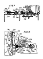
- FIG. 5 discloses a length of twist tie ribbon 22 that is disposed in a position to be twisted. The ribbon is shown in opening 115 of housing 114.
- Hoop 230 includes a head 234 having a curved surface 236. Curved surface 236 of head 234 swings in the direction of arrow I, and engages and rotates the end of twist tie ribbon 22 in the direction of arrow I around the object to be tied.
- FIG. 9 depicts hoop 230 in the closed position.
- rack 231 completes its motion in the direction of arrow H and camming member 240 contacts switch member 242 of microswitch 244.
- Microswitch 244 activates a twist head 250 to twist, microswitch 244 having been placed in an operative state by the engagement of camming member 240 with switch member 310 of microswitch 312.
- Atwist head 250 is connected to a gear train, generally indicated at 252, which includes a single rotation clutch (not shown) similar to that provided for ribbon feed wheel 40'. Accordingly, each time microswitch 244 is activated, gear 254 rotates in one 360° rotation. This causes gear 256 to rotate in one 360° rotation and causes shaft 258 to rotate likewise.
- Four- to-one step up gear 260 converts a single 360° rotation of shaft 258 to four 360° rotations of shaft 262.
- Camming member 264 is connected to shaft 262 as is twist head 250. Accordingly, each time microswitch 244 is activated, cam 264 and twist head 250 rotate four full revolutions.
- Cam member 264 bears against knife 266 and causes same to cut twist tie ribbon 22. Twist tie ribbon 22 is held between guide plates 206 and 208 of guide member 200 and, accordingly, when knife blade 268 is moved in the direction of arrow H by cam member 264, twist tie ribbon 22 is cut.
- Knife 266 and twist head 250 rotate in the direction of arrow J, such that cam member 264 bears against back surface 265 of knife member 266 so that knife blade 268 can cut twist tie ribbon 22.
- Knife 266 is pivotably mounted to second guide 200 by bolt 270. Furthermore, knife 266 pivots about bolt 270 and is biased in the clockwise direction as viewed in FIG. 8 about bolt 270 by a spring 272 extending between knife 266 and frame 114. Accordingly, cam member 264 moves knife 266 such that it pivots about bolt 270 and compresses spring 272. After cutting is complete and camming member 264 no longer cams knife blade 266, spring 272 returns knife blade 266 to the position shown in FIG. 8, wherein twist tie ribbon 22 can be displaced to fill opening 115.
- twist head 250 twists ends 22a and 22b of twist tie ribbon 22. Twist head 250 rotates about shaft 263. Twist head 250 includes a central member 280 and two curved fingers 282 and 284 for engaging the ends of twist tie ribbon 22. The fingers are integrally formed with center member 280 to define grooves 286 and 288 for receiving twist tie ribbon 22 therein. Fingers 282 and 284 are formed with tips 283 and 285 so that the tips extend past the body portions 290 and 292.
- the tie head 250 completes four full rotations and causes twist tie ribbon 22 to become twisted as shown in FIG. 10.
- FIG. 11 depicts the tied item 298 in a bundle with movable wall 300 bearing against the item to be tied and the tie ribbon 22 therearound. Twist head 250 has end 22b in groove 288 and twisted portion 22c is depicted.
- FIGS. 5, 6 and 9 Attention is next directed to FIGS. 5, 6 and 9, and, in particular, to the rack and pinion construction, wherein plate 224 is moved by the article to be tied 298 in a direction of arrow H, and hoop 230 is rotated in the direction of arrow I as disclosed above. Furthermore, rack 241, having camming member 240 thereon, is moved to contact switch 310 of microswitch 312 and bear against same. Then, camming member 240 contacts switch 242 of microswitch 244 which causes the motor to be turned on and the twist and cut operations to be performed as described above.
- Support member 220 includes a first bore therethrough for receiving post 322 and a second bore therethrough for receiving locking member 324.
- Post 322 is releasably secured by locking member 324, which lockingly engages post 322 in a direction substantially orthogonal to the direction of displacement of post 322.
- Post 322 is used to displace movable wall 300 which is used to position the object to be tied so that a tight twist tie may be produced.
- twist tie ribbon 22 will not form a tight wrap around the object to be tied 298, when the object to be tied 298 is inserted into the opening 115 and, therefore, when hoop 230 is brought around in the direction of arrow I, the tie made will not be tight. Accordingly, when a series of articles are to be tied, plate 300 is first positioned correctly by use of locking member 324.
- the present invention provides a new manner of performing a twist tie operation to receive a tight twist around a bundle to be tied.
- This method includes first displacing a predetermined amount of twist tie material, then entering the object to be tied thereon and bending the twist tie material around using hoop 230 and then causing the ends of the tie material to be inserted within a twist head 250 which rotates to close the twist tie. Since a predetermined amountoftie material 22 is dispensed, the twist tie ends can be evened after the twist is performed. This provides an aesthetically pleasing finished product.
- the operation of the device can be controlled by a control 245 shown schematically in FIG. 5 and operatively coupled to the motor (not shown), microswitches 244 and 312 and the feed wheel single rotation clutch and the twist/cut single rotation clutch.
- the motor rotates continuously, once turned on.
- hoop 230 is closed by a rack and pinion 231, 232 and microswitch 244 actuates the twist/cut single rotation clutch to effect twisting and cutting.
- microswitch 312 actuates the feed wheel single rotation clutch to feed the desired length of twist tie ribbon into the entrance of opening 115, so that the machine is ready for the next cycle.
- FIGS. 12 and 13 Attention is next directed to FIGS. 12 and 13, wherein an alternative embodiment for the mechanical portion of the object insertion structure of the second embodiment is disclosed.
- the third embodiment includes a small rack and pinion section, including rack 400 and pinion 402.
- Hoop 404 is connected to pinion 402 such that as plate 410 is moved in the direction of arrow H', and rack 400 therefor is moved, pinion 402 automatically causes hoop 404 to swing in a direction of arrow I'.
- Rack 400 and table 410 are integrally connected to slide 412, which includes camming member 414 thereon for contacting switch 420 of microswitch 422 and switch 424 of microswitch 426.
- Slide 412 is mounted in a female slide member41 which includes a flat bottom portion 417 which is mounted upon housing 114 and substantially U-shaped ends 418 and 419.
- Ball bearings 415 are disposed within U-shaped members 418 and 419 to allow slide 412 to slide along female slide member 416. As slide 412 moves in the direction of arrow H, spring 315' compresses. Upon completion of the twisting process, when the object that is tied is removed from the opening 115, pressure is released from plate 410 and spring 315' exerts pressure in the opposite direction to arrow H' and slide 412 slides in the direction opposite to arrow H'. When cam 414 contacts switch 420 of microswitch 422, a next length of tie ribbon 22 is displaced into a position to be tied.
Landscapes
- Engineering & Computer Science (AREA)
- Mechanical Engineering (AREA)
- Basic Packing Technique (AREA)
Applications Claiming Priority (2)
| Application Number | Priority Date | Filing Date | Title |
|---|---|---|---|
| US97270992A | 1992-11-06 | 1992-11-06 | |
| US972709 | 1992-11-06 |
Publications (2)
| Publication Number | Publication Date |
|---|---|
| EP0596616A2 true EP0596616A2 (de) | 1994-05-11 |
| EP0596616A3 EP0596616A3 (de) | 1995-03-01 |
Family
ID=25520034
Family Applications (1)
| Application Number | Title | Priority Date | Filing Date |
|---|---|---|---|
| EP93308191A Withdrawn EP0596616A3 (de) | 1992-11-06 | 1993-10-14 | Vorrichtung und Verfahren zum Zuführen, Schneiden und Verdrillen eines Bandes. |
Country Status (4)
| Country | Link |
|---|---|
| EP (1) | EP0596616A3 (de) |
| JP (1) | JP3434548B2 (de) |
| CA (1) | CA2106655A1 (de) |
| MX (1) | MX9306472A (de) |
Cited By (2)
| Publication number | Priority date | Publication date | Assignee | Title |
|---|---|---|---|---|
| EP0711704A1 (de) * | 1994-11-14 | 1996-05-15 | Ben Clements & Sons, Inc. | Maschine zum Verdrillen eines Bindedrahts |
| CN114082785A (zh) * | 2021-11-20 | 2022-02-25 | 贵溪世鹏金属有限公司 | 一种压延成型的金属冷热薄板的收卷机构 |
Families Citing this family (2)
| Publication number | Priority date | Publication date | Assignee | Title |
|---|---|---|---|---|
| CN119117410B (zh) * | 2024-11-12 | 2025-04-22 | 苏州潞能能源科技有限公司 | 一种光伏组件打包用上木护楞装置 |
| CN119142600B (zh) * | 2024-11-14 | 2025-05-13 | 无锡华利特纸制品有限公司 | 一种环保型纸袋成品自动输送设备 |
Family Cites Families (6)
| Publication number | Priority date | Publication date | Assignee | Title |
|---|---|---|---|---|
| US3825039A (en) * | 1972-06-05 | 1974-07-23 | Domain Ind Inc | Twist-tie bag closing machine |
| GB1537155A (en) * | 1975-07-21 | 1978-12-29 | Int Packaging Corp | Apparatus for tying articles |
| JPS5533936Y2 (de) * | 1976-09-02 | 1980-08-12 | ||
| DE2856706A1 (de) * | 1978-12-29 | 1980-07-10 | Takigawa Kogyo Co | Automatische buendelvorrichtung |
| DD216211A1 (de) * | 1983-04-04 | 1984-12-05 | Rohrkombinat Stahl & Walzwerk | Abbindegeraet fuer bandfoermiges umreifungsmaterial |
| NL192100C (nl) * | 1987-05-27 | 1997-02-04 | Takami Masaho | Machine voor het met een band omsnoeren van een produkt. |
-
1993
- 1993-09-21 CA CA 2106655 patent/CA2106655A1/en not_active Abandoned
- 1993-10-14 EP EP93308191A patent/EP0596616A3/de not_active Withdrawn
- 1993-10-18 MX MX9306472A patent/MX9306472A/es unknown
- 1993-11-02 JP JP29596993A patent/JP3434548B2/ja not_active Expired - Fee Related
Cited By (2)
| Publication number | Priority date | Publication date | Assignee | Title |
|---|---|---|---|---|
| EP0711704A1 (de) * | 1994-11-14 | 1996-05-15 | Ben Clements & Sons, Inc. | Maschine zum Verdrillen eines Bindedrahts |
| CN114082785A (zh) * | 2021-11-20 | 2022-02-25 | 贵溪世鹏金属有限公司 | 一种压延成型的金属冷热薄板的收卷机构 |
Also Published As
| Publication number | Publication date |
|---|---|
| JP3434548B2 (ja) | 2003-08-11 |
| CA2106655A1 (en) | 1994-05-07 |
| JPH07315317A (ja) | 1995-12-05 |
| MX9306472A (es) | 1994-05-31 |
| EP0596616A3 (de) | 1995-03-01 |
Similar Documents
| Publication | Publication Date | Title |
|---|---|---|
| US4655264A (en) | Twist tying machine | |
| US6663040B2 (en) | Strapper with improved winding and cutting assembly | |
| US3447448A (en) | Wire tying machines | |
| EP0139462B1 (de) | Drill-Bindemaschine | |
| JPS6099812A (ja) | 煙草パック用の包装装置 | |
| EP0460880B1 (de) | Vorrichtung zum Zuführen von Bindedraht | |
| US11091282B2 (en) | Apparatus and method for sealing or tying products | |
| EP0596616A2 (de) | Vorrichtung und Verfahren zum Zuführen, Schneiden und Verdrillen eines Bandes | |
| US4850177A (en) | Stretch bundler | |
| US4147310A (en) | Apparatus for coiling wire | |
| US3369573A (en) | Tying apparatus | |
| US6837156B2 (en) | Twist tie feed device | |
| US4013494A (en) | Tube forming method | |
| US4014734A (en) | Tube forming device | |
| WO1994021449A1 (en) | Apparatus and method for applying a twist-tie to a packaging container | |
| US2802321A (en) | Tape stapling | |
| EP0711704B1 (de) | Maschine zum Verdrillen eines Bindedrahts | |
| US4936073A (en) | Stretch bundler | |
| US2512124A (en) | Apparatus for packaging shoelaces | |
| JPS6238219B2 (de) | ||
| EP0911264B1 (de) | Etikettiermaschine für Produkte mit unregelmässiger länglicher Form wie Würste | |
| US4984410A (en) | Apparatus of winding and packaging shoelaces into pairs | |
| GB2063208A (en) | Apparatus for placing a self- adhesive tongue portion on a carrier member | |
| SU256600A1 (ru) | Автомат для завертывания бинтов и подобных штучных изделий | |
| JP2002332005A (ja) | 結束包装機 |
Legal Events
| Date | Code | Title | Description |
|---|---|---|---|
| PUAI | Public reference made under article 153(3) epc to a published international application that has entered the european phase |
Free format text: ORIGINAL CODE: 0009012 |
|
| AK | Designated contracting states |
Kind code of ref document: A2 Designated state(s): BE DE DK ES FR GB IE IT NL |
|
| PUAL | Search report despatched |
Free format text: ORIGINAL CODE: 0009013 |
|
| AK | Designated contracting states |
Kind code of ref document: A3 Designated state(s): BE DE DK ES FR GB IE IT NL |
|
| 18D | Application deemed to be withdrawn |
Effective date: 19950902 |