EP0596722A1 - Distributeur de produits semi-congelés - Google Patents
Distributeur de produits semi-congelés Download PDFInfo
- Publication number
- EP0596722A1 EP0596722A1 EP93308789A EP93308789A EP0596722A1 EP 0596722 A1 EP0596722 A1 EP 0596722A1 EP 93308789 A EP93308789 A EP 93308789A EP 93308789 A EP93308789 A EP 93308789A EP 0596722 A1 EP0596722 A1 EP 0596722A1
- Authority
- EP
- European Patent Office
- Prior art keywords
- product
- dispensing
- product container
- containers
- container
- Prior art date
- Legal status (The legal status is an assumption and is not a legal conclusion. Google has not performed a legal analysis and makes no representation as to the accuracy of the status listed.)
- Withdrawn
Links
Images


Classifications
-
- A—HUMAN NECESSITIES
- A23—FOODS OR FOODSTUFFS; TREATMENT THEREOF, NOT COVERED BY OTHER CLASSES
- A23G—COCOA; COCOA PRODUCTS, e.g. CHOCOLATE; SUBSTITUTES FOR COCOA OR COCOA PRODUCTS; CONFECTIONERY; CHEWING GUM; ICE-CREAM; PREPARATION THEREOF
- A23G9/00—Frozen sweets, e.g. ice confectionery, ice-cream; Mixtures therefor
- A23G9/04—Production of frozen sweets, e.g. ice-cream
- A23G9/22—Details, component parts or accessories of apparatus insofar as not peculiar to a single one of the preceding groups
- A23G9/28—Details, component parts or accessories of apparatus insofar as not peculiar to a single one of the preceding groups for portioning or dispensing
- A23G9/281—Details, component parts or accessories of apparatus insofar as not peculiar to a single one of the preceding groups for portioning or dispensing at the discharge end of freezing chambers
- A23G9/283—Details, component parts or accessories of apparatus insofar as not peculiar to a single one of the preceding groups for portioning or dispensing at the discharge end of freezing chambers for filling containers with material
-
- A—HUMAN NECESSITIES
- A23—FOODS OR FOODSTUFFS; TREATMENT THEREOF, NOT COVERED BY OTHER CLASSES
- A23G—COCOA; COCOA PRODUCTS, e.g. CHOCOLATE; SUBSTITUTES FOR COCOA OR COCOA PRODUCTS; CONFECTIONERY; CHEWING GUM; ICE-CREAM; PREPARATION THEREOF
- A23G9/00—Frozen sweets, e.g. ice confectionery, ice-cream; Mixtures therefor
- A23G9/04—Production of frozen sweets, e.g. ice-cream
- A23G9/22—Details, component parts or accessories of apparatus insofar as not peculiar to a single one of the preceding groups
- A23G9/28—Details, component parts or accessories of apparatus insofar as not peculiar to a single one of the preceding groups for portioning or dispensing
Definitions
- This invention relates to chilled product dispensing apparatus and, more particularly, to apparatus for dispensing chilled or soft frozen food products such as ice creams, frozen yogurts, custards, and the like.
- Apparatus for dispensing soft frozen food products are of commercial interest for installations in retail establishments, wherein they are operated by customers or employees for dispensing soft frozen products into individual containers such as serving dishes or edible cones.
- Soft serve products i.e., chilled or soft frozen products, are maintained within such a dispensing apparatus at a temperature which is not so low as to prevent the extrusion of a continuous stream or ribbon of the mixture, yet not so high that the extruded product is sufficiently fluid that it does not retain its shape for a period of time in the container.
- temperatures suitable for the dispensing of products with relatively high fat contents, such as ice creams are lower than those appropriate for low-fat products, such as dietetic yogurts and the like. Excessively low temperatures often have deleterious effects upon the taste and consistency of the product, which may crystallize and become undesirably hard and which may not flow consistently during operation of the dispensing apparatus.
- the temperatures at which such soft frozen confections are maintained for dispensing the products are thus rather critical, and they are somewhat higher than those preferred for storing the products.
- Refrigerated soft serve mixing and processing apparatus of a first type have been developed which are operable to process and freeze the products on-site, suitably at retail establishments in which the products are to be sold to the public.
- a liquid mix is typically converted into a soft frozen confection by lowering the temperature of the mix within a refrigerated vat while stirring the mix with an agitator or dasher.
- on-site production of soft serve products entails a number of disadvantages and difficulties. First, processing the liquid mix and bringing it to a desired subfreezing temperature is inconvenient and time consuming.
- the dasher assembly and other movable components in such an apparatus must be periodically cleaned and serviced, and the mechanical drive mechanism required for operating the dasher includes a number of moving parts which may be subject to malfunctions.
- the liquid mixtures utilized in such apparatus are more susceptible to bacterial contamination than is the case with products which are consistently maintained in a frozen state, and, accordingly, cleaning and disinfecting of the components must be performed frequently if bacterial contamination is to be avoided.
- on-site processing systems typically are operated by various employees of local retail establishments, it is difficult to maintain consistent quality control, and the resultant product may be inferior in taste and consistency to one which is processed in a central location, under carefully controlled conditions, and shipped to the retail establishment in frozen form.
- the process of air entrapment within the mix by the rotating dasher as the mix is cooled to a freezing temperature is difficult to perform consistently in such on-site processing apparatus, often resulting in the product having insufficient air entrapment.
- the product may not have the desired consistency, and the yield is reduced, which may affect the ongoing costs and profitability of the installation.
- a second type of soft frozen product dispensing apparatus in which the product is shipped in suitable containers in pre-processed, hard frozen form, suitably at sub-zero temperatures, and "tempered", or brought to somewhat higher, serving temperature ranges (e.g., 10°F. to 20°F.) within the dispensing apparatus.
- the mixture normally is shipped within containers which are adapted to be removably inserted within a refrigerated cabinet, and means have been provided for dispensing the mixture through one or more dispensing nozzles formed in a panel or door of the cabinet.
- the product is thus prepared and processed in a central facility, and a high degree of quality control may thereby be maintained.
- such dispensing apparatus are conveniently operated as self service units, wherein a customer may dispense the product into a serving container by actuating a valve on the apparatus.
- One means for serving different types of soft serve products is to provide multiple dispensing units, each with an independently controlled refrigeration system for maintaining each product within its appropriate temperature range.
- a single unit can be employed in which several soft frozen products are maintained at a single temperature which represents a compromise for one or more of the products, albeit resulting in the previously mentioned deleterious effects upon the taste and consistency of the product.
- the first alternative is undesirably expensive, entailing the initial costs of multiple refrigerated units and substantial continuing expenses related to power consumption and maintenance.
- multiple refrigerated units would require an excessive amount of floor space, which is also competitively disadvantageous, particularly for small business establishments.
- the second alternative is clearly undesirable from the standpoints of product quality and customer satisfaction. Accordingly, there is a need for a soft frozen food product dispensing apparatus in which containers of soft frozen products of differing types may be conveniently maintained at selected temperatures appropriate for each type of soft serve product.
- a further disadvantage of existing systems of the type adapted to dispense previously processed frozen products is that the entire interior volume of the cabinet or housing in which containers of soft frozen product are housed is required to be maintained under refrigeration, within a desired temperature range.
- the necessity for maintaining a consistent, precisely controlled temperature throughout the cabinet presents technical difficulties, and the costs of electrical power for continuously refrigerating the entire cabinet at subfreezing temperatures are substantial.
- the generally cylindrical containers of pre-processed frozen confections may tend to become adhered to chilled receptacles or other components within the dispensing unit, because of the freezing of condensation which may form between the containers and adjacent components, whereby the containers tend to become adhered to components within the refrigerated units and are difficult to remove.
- a further limitation inherent in such existing soft serve dispensing apparatus relates to the difficulty of ensuring that the soft frozen product in a respective container is substantially exhausted prior to replacement of the container, and the related difficulty of monitoring the quantity of product remaining in each container to ensure that empty or "nearly empty” containers are identified and replaced in a timely and systematic manner. With respect to customer satisfaction and volume-of-sales considerations, it is thus preferable that empty or nearly empty containers are replaced by an operator or service person prior to receiving customer complaints regarding an empty, and supposedly inoperative, machine.
- the containers of pre-processed soft frozen food products are typically of cylindrical configuration having a tubular housing and a flexible, impervious liner or bag extending within the tubular housing.
- the flexible bag typically has a closed end and an opposite, open end communicating through an outlet conduit and dispensing valve within the dispensing apparatus, and subsequently with a dispensing nozzle.
- the product has been dispensed by means of a piston member adapted to urge the liner and its contents toward the outlet.
- piston members for example, have been actuated by expandable bellows mechanisms.
- a force is thereby applied against the closed end of the flexible liner sufficient to cause the liner to be translated inwardly within the rigid, tubular housing, urging the flexible liner and its contents toward the outlet.
- the containers heat sink structure contained within the flexible liner for preventing the occurrence of locally heated regions within the container, and adjacent its outlet, which would tend to result in an inconsistent, partially liquid product.
- this system entails a number of advantages over ordinary, piston-actuated extrusion mechanisms employed in conventional dispensing apparatus, precise determination of the quantity of mixture remaining in the container is difficult because of the distortion and irregularity of the flexible liner as it is compressed within the tubular housing and within the heat sink structure.
- dispensing of the soft frozen product is controlled by various types of valving mechanisms.
- Some systems have employed manually operated, proportionally actuable valves, wherein a customer may adjust the valve by a desired degree, generally by shifting a handle operably connected to a valve element.
- manually actuated dispensing systems entail certain disadvantages, particularly when the soft serve dispensing apparatus is to be used in a self-service mode wherein customers using the machine may not be familiar with its operation or with the fluid characteristics of the mixture as it is extruded. For example, a customer may have difficulty in controlling such a proportionally actuable valve to achieve a desired rate of flow of the mixture.
- a soft serve dispensing apparatus having an improved valving and shutoff system for controlling the extrusion of soft serve confections, wherein the dispensing valve is normally closed, and is automatically returned to a closed position after use unless purposefully maintained in an open position by an operator, and wherein gas under respectively appropriate pressure levels is applied for actuating the dispensing valves and for ejecting the soft serve product.
- Another object of the invention is to provide such a soft serve product dispensing apparatus which is conveniently operable in a self-service mode.
- a further object is to provide such a soft serve product dispensing apparatus in which various types of soft serve products may be maintained at differing temperatures appropriate for the respective products.
- Another major object is to provide such a soft serve product dispensing apparatus which is particularly adapted to chill and dispense soft serve products in containers of the type having an elongated flexible bag or liner containing the product, and an elongated heat sink structure, the product dispensing apparatus having cooling sections respectively located adjacent each container, in alignment with the respective heat sink structure of each container, for effectively removing heat from the soft serve product by cooling the respective heat sink structures.
- Yet another object is to provide such a soft serve product dispensing apparatus having a cabinet or housing in which containers of soft serve product are maintained within respective, precisely controlled temperature ranges, but wherein it is not necessary to refrigerate the entire interior volume of the housing or cabinet.
- a further object is to provide such a soft serve product dispensing apparatus which includes refrigerated receptacles or barrels for receiving respective containers of pre-processed frozen products and a system for quickly and conveniently defrosting the receptacles for facilitating replacement of the containers and servicing of the apparatus.
- Yet another object is to provide such a soft serve product dispensing apparatus which includes an effective monitoring system for detecting the existence of an empty or nearly empty container of the soft frozen product, and which includes means providing an indication to an operator of the existence of an empty or nearly empty container, thereby permitting replacement of such containers in a timely manner.
- a related object is to provide such a self-service, soft serve dispensing apparatus which includes a product dispensing valve which is normally closed and which may be conveniently opened by a switch actuated by a customer, and wherein the dispensing valve returns to a closed position upon release by the customer of the product dispensing switch.
- a further, related object is to provide such a valve actuating system which includes means for damping the operation of the valve actuating mechanism during opening and closing of the valve to minimize physical shock and noise during operation of the product dispensing system.
- a soft serve product dispensing apparatus which is adapted to dispense pre-processed soft frozen food products of several types and consistencies, maintaining containers of the respective soft serve products at differing temperatures appropriate for dispensing the respective soft serve products.
- a selectively controllable refrigeration system is provided in which a coolant is conducted through multiple supply conduits to respective cooling units, which include receptacles in which the respective containers of soft frozen products are removably seated.
- coolant is conducted to respective product container receptacles, and a defrosting system is provided having selectively controllable communication between a compressor section and the container receptacles.
- the defrosting system is operable for selectively conducting heated, pressurized coolant through cooling sections adjacent the respective receptacles for heating and defrosting the receptacles, thereby facilitating removal and replacement of respective containers of product seated within the receptacles, and servicing of the apparatus.
- a pneumatic actuation system for applying a pressure differential within the respective containers of soft frozen product which is effective to cause the product to flow in a steady stream through an outlet conduit and dispensing nozzle, a normally closed dispensing valve being provided for controlling the flow of soft serve product through the dispensing nozzle.
- Electrical and pneumatic control systems are provided for effecting opening of the valve in response to closing of a normally open actuating switch, and a control system is provided which ensures that appropriate actuating pressures are maintained within a container of the product when the switch is actuated and for a predetermined time interval thereafter.
- means are provided for damping movement of the valve element.
- the damping system includes a pneumatic and hydraulic damping system.
- an electrically and pneumatically controlled system for introducing gas under a first pressure from a first tank for effecting extrusion of a soft frozen product, and for supplying gas under a second, relatively higher pressure, contained in a second tank, for actuating a product dispensing valve to control the flow of a soft frozen product, and wherein a pneumatic control and valving system is provided for supplying gas under pressure from a single source of gas under pressure, such as an air compressor, to the two tanks.
- an electronically and pneumatically controlled system for detecting the existence of an empty or nearly empty product container and providing an indication of such a condition to permit timely and systematic replacement of empty product containers.
- a control system and logic circuit is provided for determining the existence of a predetermined interior volume of gas within a respective product container which is indicative that the volume within the container, but external of the flexible liner, has become greater than a predetermined value corresponding to a "product-empty" condition.
- a pneumatic and electronic system which is operable to introduce gas under pressure within the respective food product containers and then to permit release of the gas under pressure through a restrictive orifice, while sensing the time required for the pressure of the gas to fall by a predetermined increment as it is exhausted through the restrictive orifice, comparing the time delay with a predetermined reference delay period, and providing a "product empty" signal when the predetermined delay period is exceeded.
- the restrictive orifice is adjustable for permitting calibration or adjustment of the system.
- the apparatus includes means for maintaining frozen food mixtures within individual, removable containers at selectively controlled temperatures within suitable temperature ranges.
- suitable temperature ranges For example, a temperature range of 10-20 degrees may be typical. Other products may require other temperatures, which may range from 0°F. to 50°F.
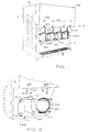
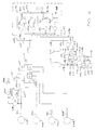
- the chilled or soft frozen food product dispensing apparatus 10 of one preferred embodiment of the invention suitably includes a cabinet 12 suitable of rectangular configuration having an upper front panel 14 which is connected to sidewalls 15, 16, and a lower front panel 18 on which product dispensing head assemblies 20a, 20b, 20c, 20d are removably mounted.
- a first chilled product receptacle 22a includes a cylindrical product barrel 24a, preferably of stainless steel or aluminum, having a forward end portion mounted within corresponding opening 21 formed through front panel section 18, and a rearward end portion sealingly mounted within an annular cover or cap member 26.
- Cap member 26 has a centrally formed opening 28 communicating with a rearwardly extending, high pressure conduit 30, for reasons which will become apparent from the description to follow.
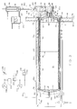
- soft serve product 32 which for illustrative purposes in the present description will be considered to be a soft frozen dietetic yogurt confection having a preferred serving temperature range of about 15°F. to 20°F., is contained within a cylindrical product container 34a which is removably seated within the cylindrical, chilled product receptacle 22a.
- Product container 34a includes an elongated, rigid, tubular housing member 36, adapted to seat within the cylindrical barrel 24a of chilled receptacle 22a, the tubular housing member having an outer diameter slightly smaller than the inner diameter of the chilled product receptacle barrel 24a for permitting sliding insertion of filled product containers within the barrel, and removal of empty containers.
- the tubular member 36 is suitably formed of a helically wound, rigid cardboard or paper material, or it may be of other thin, stiff, lightweight materials.
- a flexible, elongated, impervious bag 38 suitably of 4 mil polyethylene material, extends rearwardly within the tubular housing member 36 and has a forward, open end portion 40 which is folded over the forward end of tubular member 36, and a rearward, closed end portion 42 which extends across the tubular member 36 adjacent the end cap 26 when the product container 34 is filled with the soft serve product 32, as seen in FIG. 3.
- the open end portion 40 of product bag 38 is protected by a removable cover, not shown, fitted over the forward end of tubular member 36.
- the head assembly 20a is suitably formed of a rigid plastic material such as polypropylene or acrylic, and has a rearwardly open housing portion 44 of generally cup-shaped configuration adapted to fit sealingly over the barrel 24a, and the housing 44 having a semi-frustoconical lower wall portion 45 coaxial with a forwardly projecting, cylindrical extension portion 46 defining a dispensing port 48.
- the housing 44 has a rearwardly projecting, peripheral annular flange portion 50 which is adapted to seat coaxially within the forward end portion of the container tubular housing member 36, thereby fitting tightly within the folded over forward end portion 40 of the flexible bag 38 for effecting sealing engagement between the bag 38 and an annular seal 52, which is press fitted within an outwardly flanged forward portion 53 of the receptacle barrel 24a and which encircles the tubular member 36. Because of the outwardly flanged end portion 53 of barrel 24, the resilient seal 52 is pressed securely into sealed relation with the confronting surfaces of the barrel flange 53 and overlapped portion 40 of bag 38 upon the head assembly 30a being urged against the product container receptacle 22. Additionally, a second O-ring seal 54 is seated within a corresponding annular groove formed in an annular, rear wall of housing 44, in register with the forward portion 53 of cylindrical receptacle barrel 24a.
- the cylindrical product container 34a in its preferred embodiment, also includes a heat sink dispensing tube structure 56 contained within the bag 38.
- the heat sink structure 56 includes a tubular barrel portion 58 extending rearwardly within the flexible bag 38 from its forward portion 40, and extending coaxially of the product container tubular member 36.
- a perforated extrusion head portion 60 of the heat sink structure 56 extends across the forward end of barrel portion 58.
- the extrusion head portion 60 includes a plurality of openings 62 through which the frozen confection 32 may flow when the product is dispensed.
- An extrusion head projection member 64 extends forwardly from the extrusion head 60 and coaxially within the product dispensing port 48.
- the heat sink dispensing tube structure 56 is constructed of a material having a high coefficient of thermal conductivity, such as aluminum, and one of its purposes is to create a thermal heat sink for ensuring that the temperature of the soft serve product 32 remains substantially consistent within the dispensing port 48. Without the heat sink structure 56 the soft serve product would be subject to localized heating since the head assembly housing 44 is exposed to the nonrefrigerated environment external of the cabinet 12.
- the heat sink dispensing tube structure 56 preferably extends within the receptacle barrel 24 for a distance equal to about 50 percent of the length of the barrel for effective dissipation of heat within the product container and the outlet port 48.
- an insulating cone member 66 of generally frustoconical configuration is coaxially seated within the inwardly projecting flange portion 50 of the head assembly housing 44 and includes a forwardly projecting cylindrical extension 68 extending coaxially within the dispensing port 48, the cylindrical extension 68 being sealingly seated, by annular seal 69, within cylindrical portion 70 of the dispensing head assembly 20a.
- a helical cooling coil 74a of high pressure tubing suitably 3/4-inch copper tubing, encircles the cylindrical barrel 24a of chilled product receptacle 22a at a location adjacent the heat sink dispensing tube 56.
- a refrigerant such as freon 502 may be conducted through the cooling coil 74a for cooling the receptacle 22 and its contents, whereby heat is withdrawn from the cylindrical barrel 24a, the tubular member 36, the heat sink dispensing tube 56 and the soft frozen confection 32 within container 34 and dispensing port 48, thus dissipating heat within these 74a, 74b, 74c, 74d (FIG. 6) elements away from the product dispensing pathway.
- freon 502 may be conducted through the cooling coil 74a for cooling the receptacle 22 and its contents, whereby heat is withdrawn from the cylindrical barrel 24a, the tubular member 36, the heat sink dispensing tube 56 and the soft frozen confection 32 within container 34 and dispensing port 48, thus dissipating heat within these 74a, 74b, 74c, 74d (FIG. 6) elements away from the product dispensing pathway.
- cooling coil 74a, and cooling coils 74b, 74c, 74d institute evaporator sections in which refrigerant is permitted to evaporate for cooling the respective product container receptacles 22.
- the soft serve product 32 is cooled by cooling coil 74a and is prevented from becoming heated, and softening, by the heat sink dispensing tube structure 56.
- the product container receptacle 22a is insulated by means of an insulating jacket 76, suitably formed of a closed-cell foamed material, extending around the cylindrical barrel member 24a and the cooling coil 74a and extending rearwardly around the cap member 26.
- the front panel 18 of the cabinet 12 is insulated suitably including an internal layer 77 of closed cell insulating material sandwiched between front and rear metal sheets 78, 80.
- a second function of the heat sink dispensing tube structure 56 is to support the flexible bag 38 to prevent premature collapse of the bag and to ensure that it collapses in upon itself over the rear edge of the heat sink dispensing tube upon pressure being applied to urge the flexible bag 38 forwardly within barrel portion 58.
- the soft serve confection 32 is urged forwardly and caused to flow through the openings 62, within extrusion head 60, and subsequently through the cylindrical projection 68, the dispensing port 48, and product dispensing valve assembly 82.
- Pressure is applied over the external surface of the flexible bag 38 by the introduction of a gas under pressure within the interior volume 83 of chilled product receptacle 22, external of the bag 38, and differential pressure across the bag thereby effects extrusion of the product 32 through dispensing nozzle 84, upon valve assembly 82 being open.
- Valve assembly 82 includes an elongated, cylindrical piston valve member 86 slidably seated within a valve chamber 88 vertically formed through head assembly 20a. In its closed position as shown in FIG. 3, the valve member 86 extends across the dispensing port 48, upper and lower O-ring seals 90, 92 being seated within respective annular grooves coaxially encircling the valve member 86 and located above and below the dispensing port 48, for preventing leakage of the soft serve product 32 when the valve member is in its closed position.
- the upper end portion of valve member 86 is connected with the lower end of a piston rod 94, which extends upwardly within an actuator 96, and is connected to piston member 98, which is slidably seated within chamber 100 of the actuator 96.
- the piston rod 94 is connected at its lower end portion to draw valve coupling 102, which is connected to valve member 86 by means of a ball member 104 seated within a socket 106 formed in the upper end portion of valve member 86, through a keyhole slot 108 which permits convenient disassembly and removal of the piston rod 94 from the piston valve member 86 for ease of cleaning and assembly.
- the dispensing head assembly 20a is removably mounted on the cabinet lower wall portion 18, in sealing engagement with the outer end of the receptacle barrel 22a, by means of flanged nuts 110a, 110b which are threadingly engaged with outwardly projecting bolts 112a and 112b.
- Bolts 112a, 112b are suitably fixedly mounted within a vertical bracket member 114 which is welded or otherwise rigidly affixed to one side of the cylindrical barrel 24a.
- a second bracket member, not shown, is welded to the opposite side of the barrel 22a for supporting bolts which are threadingly engaged by the third and fourth flanged nuts 110c, 110d (FIG. 2).
- annular seals 52, 54 (FIG. 3) are brought into sealing contact with the flanged end portion 53 and the folded over portion 40 of the bag 38 for effecting sealing engagement between the bag 38 and receptacle barrel 24a.
- the containers 34 of pre-processed soft serve product are supplied in hard frozen form.
- the soft frozen product 32 is poured into the flexible bag 38, and the open end of the bag is temporarily sealed in a removable cover while the product is hard frozen.
- the frozen food product may then be shipped, and stored, until such time as it is tempered and placed into the receptacle 22, wherein it is maintained at a higher temperature in a soft serve consistency for permitting dispensing of the product through the dispensing nozzle 84.
- each of several containers of soft serve product is provided.
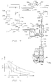
- individual control of the temperatures of multiple (four) respective food containers is provided by controlling the flow of coolant to evaporator coils 74a, 74b, 74c, 74d of each refrigerated product dispensing unit 116a, 116b, 116c, 116d.
- a single refrigerant condensing unit 118 is provided having a compressor 120 connected through conduit 121 with a condenser unit 122.
- a commercially available condensing unit 118 such as Model MSYL-0027, manufactured by the Coplend Corporation is suitably employed for compressing and condensing the refrigerant, whereby the refrigerant may be conducted under high pressure, in liquid form, to the evaporator coils 74a, 74b, 74c, 74d.
- the condensing unit 118 includes a compressor 120 driven an electric motor, not shown, of one-quarter horse power.
- the refrigerant in high pressure gaseous form, is conducted along connecting line 121 to the condenser unit 122, which condenses it to liquid form and transmits it through outlet line 124 and liquid coolant supply line 126 to a manifold line 128 connected to first, second, third and fourth solenoid valves 130a, 130b, 130c, 130d.
- a drier unit 132 suitably drier unit DX 052 manufactured by the Danfoss Corporation, is connected in series between outlet line 124 and supply line 126 for removing any moisture from the refrigerant.
- the solenoid valve 130a is actuated by power supply 134, suitably a 24 volt AC source, within a control circuit 136, to be described.
- An adjustable thermostatic control unit 178a is provided including an adjustable thermostat 140 operatively connected to a normally open switch connected in series with power supply 134 and the coil 143a of solenoid valve 130a.
- the thermostat 140 is adjustable by an operator for selecting a desired temperature for a given product, to be refrigerated and dispensed by the respective product dispensing unit 116a.
- the thermostatic temperature control unit 138 thus includes an adjustable thermostat 140 controlling a normally open electrical switch 178a connected in series with power source 134, and solenoid valve 130a.
- the thermostat sensor 140' is preferably mounted internally of the insulation jacket 74 adjacent the stainless steel barrel 24 for sensing the temperature of the barrel 24 and the adjacent product 32.
- the thermostat 140 is selected for the temperature range desired, and in the present embodiment a thermostat such as Model No. 2E740 manufactured by The Dayton Corporation and having a range of -30°F. to 70°F., is suitably employed.
- thermocouple 144 is similarly mounted within the insulation jacket 76 adjacent receptacle barrel 24 (FIG. 3), and is connected by lead 146 (FIG. 6) to an external digital thermometer 148, which, as seen in FIG. 1, is suitably mounted on the cabinet front panel 14 adjacent the respective head assembly 20a. Similar thermometers and thermocouples are provided for the other product dispensing units 116b, 116c, 116d.
- a conventional, thermostatic expansion valve 130a is connected in series between the solenoid valve 150 and the evaporative cooling coil 74a for controlling the flow of refrigerant through supply line 152 to the coil 74a, supply line 152 suitably being continuous with the coil 74a.
- the thermostatic expansion valve 150 is connected by tubing 154 to a power bulb sensing element 156, as shown also in FIG. 3, mounted on refrigerant return line 158.
- the orifice of the thermostatic expansion valve 150 is adjusted proportionally to the temperature related signal received through tubing 154 for controlling the refrigerant flow.
- Expansion valve 150 thus serves to maintain an efficient rate of evaporation and superheating of the refrigerant as it flows through the coil, and withdraws heat from the adjacent product receptacle 22a (FIG. 3).
- Refrigerant thus flows through supply line 152 in compressed liquid form and refrigerant exiting from the evaporator coil 74a returns in a vaporous state through return line 158, manifold 128 and through the low pressure suction or return line 160 to the condensing unit 118.
- a defrosting system 162 which employs heated refrigerant in a gaseous state, in which it has been compressed by compressor 120 but prior to being cooled by the condenser 122.
- defrosting of the receptacles 22a (FIG. 3), is occasionally necessary to free one of the product containers 34 which may have become adhered to the adjacent chilled product container receptacle 22 because of the formation of ice between the respective barrel 24 and the container 34 due to condensation on the surface of the cooled, subfreezing barrel 24 over time.
- the high pressure conduit 121 connected between the compressor 120 and the condenser 122 conducts refrigerant in a gaseous state, which has been compressed and heated by the compressor, to the condenser 122 for cooling and liquification.
- the defrosting system includes a shunting conduit 163 connected between high pressure conduit 121, through a solenoid actuated defrost control valve 164, to a defrost manifold line 172.
- defrost solenoid valve 164 which is actuated by a normally open time delay relay 179 (FIG. 8) having normally open switch contacts 180 connected in series with a power supply 170 for controlling solenoid valve 164, which is normally closed until opened by the relay.
- the electrical circuitry of the defrost supply is shown in FIG. 8.
- Defrost switch 168 is physically positioned on the exterior of the cabinet 12 (FIG. 1) for convenient actuation by an operator.
- time delay relay 179 Upon being actuated by the push button operated switch 168, time delay relay 179 is energized and closes normally open relay switch elements 180 (FIG. 8) to energize solenoid coil 166 to maintain the solenoid valve 164 (FIG. 6) in an open condition for approximately three minutes, permitting heated gases to be conducted from line 163 (FIG.
- the temperatures of the product receptacle barrels 24 are approximately 35°. In some instances, a subsequent three-minute cycle may be required to free a heavily frozen container. Subsequent to the three minute time delay, and normally, after the removal of the product containers 34, the solenoid valve 164 is again closed, and cooled refrigerant from condenser 122 (FIG. 6) is again conducted through the evaporator coils 74a, 74b, 74c, 74d to quickly bring the temperatures of the product container receptacles down to a preferred range of, for example, 15-20 degrees.
- the receptacles will thereby be cooled to operative temperatures within about 15 to 25 minutes.
- Unidirectional check valves 174a, 174b, 174c, 174d are provided to prevent reverse flow of the cooled refrigerant from one of the cooling coils, e.g., coil 74a, to the other coils during the refrigerant cycle, which, during normal cooling operations, would interfere with the individual temperature control effected by the respective coils.
- means are provided for selectively adjusting the temperature within the respective product container receptacles 22 and for turning off the compressor 120 when all of the refrigerant supply solenoid valves 130a, 103b, 130c, 130d are closed, for preventing over-pressurization of the refrigerant should the compressor continue to pump the refrigerant against the closed solenoid valves.
- an OR logic system is provided, as shown in FIG. 8, for sensing the closure of the respective solenoid valves 130a, 130b, 130c, 130d (FIG. 6).
- the electrical coils 143a, 143b, 143c, 143d of solenoid valves 130a, 130b, 130c, 130d are connected in series with outlet leads 176a, 176b, 176c and 176d, which are connected to respective adjustable thermostat switches 178a, 178b, 178c, 178d, which are operable to close their respective switch elements to apply power to open solenoid valves 130a, 130b, 130c, 130d when the temperatures within the product receptacles, as sensed by their respective sensor elements 140 (FIGS. 3, 6) rise above the temperature set in the thermostats.
- thermostats 178a, 178b, 178c, 178d are closed, they are operable to emit signals to energize and open the respective solenoid valves 130a, 130b, 130c, 130d to effect cooling of the respective product container receptacles, thereby permitting adjustment, by adjusting variable thermostats 178a, 178b, 178c, 178b, of the temperature within each product container receptacle. Adjustment of the temperatures is accomplished by adjusting the thermostat settings, by rotating screws 179, as shown in FIG. 2, positioned adjacent the respective product dispensing heads.
- OR logic circuit comprising relay 184, connected in series with paralleled diodes 186a, 186b, 186c, 186d, connected respectively with lines 176a, 176b, 176c, 176d, is provided for maintaining relay 184 in an actuated state, should any one of the relay switches 178a, 178b, 178c, 178d be closed wherein any one of the solenoid valves 130a, 130b, 130c, 130d (FIG. 6) are open for conducting refrigerant.
- time delay relay 187 provides a 15 minute delay to prevent starting the compressor against an existing high pressure.
- Capacitor 188 is connected in parallel with relay coil 184 for smoothing the DC voltage applied to relay coil 104. In the event all of the switches 178a, 178b, 170c, 178d are open, whereby all of the solenoids 130a, 130b, 130c, 130d are closed, to prevent flow of refrigerant from the compressor 120 (FIG.
- the relay 184 is deactivated, whereby the normally open switch 186 is open, turning off the compressor 120 to stop further compression of refrigerant.
- the normally open switch 193 which is another relay switch element of relay 179 is closed to energize relay 191 to close switch 167, turning on the compressor 120.
- extrusion of the soft serve product 32 is effected by means of a pneumatically actuated system 200 which is operable to supply gas under pressure at, for example, 40 p.s.i., from a supply of air under pressure, to be described, through line 30a (FIG. 3) and liners 30b, 30c, 30d to the chambers defined within the product receptacles 22a, 22b, 22c, 22d, for urging the soft serve product 32 forwardly and outwardly through the dispensing nozzles.
- a pneumatically actuated system 200 which is operable to supply gas under pressure at, for example, 40 p.s.i., from a supply of air under pressure, to be described, through line 30a (FIG. 3) and liners 30b, 30c, 30d to the chambers defined within the product receptacles 22a, 22b, 22c, 22d, for urging the soft serve product 32 forwardly and outwardly through the dispensing nozzles.
- the pneumatic system is also operable for actuating the dispensing valve opening and closing mechanisms.
- a normally open product dispensing switch 202 is actuated by push button 204 which is conveniently located on the cabinet front panel 14, as seen in FIG. 1, adjacent the first head assembly 20a.
- product dispensing switch 202 is depressed by a customer wishing to dispense a quantity of the soft serve product contained within the respective, adjacent product dispensing unit.
- product dispensing switch 202 is connected between a low voltage DC power supply 242, and the coil 206 of normally closed solenoid valve 208, which is connected in series between a high pressure source 210 of gas under pressure, to be described.
- the high pressure source 210 is suitably a source of compressed air, of about 100 p.s.i., as will be described with respect to FIG. 9.
- Fluid-dampened product dispensing valve actuating system 212 includes a fluid accumulator 214 partially filled with a supply of a stable viscous liquid 216 such as glycerine, suitably of 97 percent purity, within the reservoir 218.
- Accumulator 214 includes a restrictive outlet orifice 220, suitably of three to five millimeters in diameter, which is connected through conduit 222 to lower chamber portion 224 of dispensing valve actuator 96. The purpose of the accumulator 214 is to dampen the application of actuating liquid to actuator 96, as will now be described.
- solenoid valve 208 When solenoid valve 208 is opened, in response to closing of product dispensing switch 202, high pressure gas is conducted via conduit 207, through solenoid valve 208 to the volume 226 within accumulator reservoir 218 above the glycerine 216, and the resulting increase of pressure within the reservoir 218 forces the glycerine outwardly through restrictive orifice 220 and conduit 222, whereby glycerine is introduced into lower chamber portion 224 of the actuator 96 beneath piston member 98 for urging the piston member upwardly. Upward movement of piston member 98 effects upward movement of piston rod 94.
- Piston rod 94 includes an upper segment 94a and a lower segment 94b, the lower segment being connected to coupling 102 which is connected to valve member 86 of the dispensing valve 82 (as also seen in greater detail in FIG. 3).
- the accumulator 214 serve to damp the response of actuator 96 to application of high pressure air applied when solenoid valve 208 is opened. Pressure is permitted to accumulate within chamber 226, and the glycerine oil 216 flows through orifice 220 and conduit 222 in a dampened, gradually accelerating stream, whereby the movement of piston 98 and valve member 86 is correspondingly dampened.
- closing of the product dispensing switch 202 is also effective to effect the application of what will be termed "low pressure gas," which is suitably air under pressure of about 40 p.s.i., to the empty volume 83 within chilled product receptacle 22a (FIG. 3) for urging the flexible bag 38 and its contents forwardly through the outlet port 48 and now opened dispensing nozzle 84, as will now be described.
- the upper section 94a of actuator piston rod 94 includes a tapered upper end portion defining a bevelled surface which is aligned with a microswitch element 230 operatively connected to normally open microswitch 232.
- Microswitch 232 is connected by conductors 234a, 234b and 236, between conductors 238, 240, conductor 238 being connected to a positive terminal of flow voltage (e.g., 24 V DC) power source 242, and conductor 240 being connected, when switch 202 is closed, to ground.
- Conductors 234a, 234b are connected in series with a first, V1 solenoid valve 244, the valve element of which is connected by conduit 246 to the low pressure, 40 p.s.i. air source, to be described, and conduit 30 which is connected in communication, through opening 28 (FIG. 3) with the interior volume 83 within product container receptacle 22a (FIG. 3).
- the closing of micro-switch 230 also effects the actuation of a time delay circuit system for maintaining "low pressure gas" within the chamber 83 for a predetermined time period, e.g., for 30 minutes, as will now be described.
- Closing of microswitch 232 is effective to connect power supply 242 to solenoid 248, operatively connected to normally open (V2) valve V250 normally open solenoid valve 250 is closed upon actuation by current conducted through the microswitch 232, in response to closing of the dispensing switch 202, and the valve 250 remains closed for a period of time subsequent to this operation, as will be described hereinbelow.
- closing valve 250 is effective to maintain an appropriate pressure within product receptacle 22a during application of low pressure gas, i.e., 40 p.s.i. to eject the product.
- the purpose of the time delay system is to maintain pressure within the receptacle 22a for a preselected period of time and subsequently release and remove the pressure from the system, at a selected time after operation of the system.
- actuating pressure is maintained for a period of time after each use so that the product may be dispensed quickly by a subsequent customer, but operating pressure is released after the selected time period to reduce strain upon elements of the system and to extend the life span of the system and also to prevent deterioration of the soft serve product 32 which may occur if it is maintained under high pressures for an extended period of time.
- third solenoid actuated valve 208 (V3) has fluid communication through conduit 207 with the source of high pressure gas, and, through conduit 224, with the accumulator 214.
- Coil 206 of solenoid valve 208 is connected through product dispensing switch 202 with power supply 242. (normally open push button preferably being mounted on the top or side of the cabinet for actuation by an operator.)
- An additional solenoid actuated relief valve 252 (FIG. 9) is suitably provided in connection with a common exhaust chamber 254 for permitting the removal of low pressure gas within the system when it is desired to remove the head assemblies 20 for serving or, for replacement of empty food containers with full containers.
- Solenoid valve 208a is a three-way valve having an outlet 256, and when is closed, communication is provided between exhaust outlet opening 256 and conduit 209, whereupon pressure is released from chamber 218 above the glycerine fluid 216 within accumulator 214.
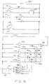
- the pneumatic circuits of the apparatus are shown in schematic form, wherein the pneumatic system for actuating the dispensing valves 96 is shown generally ag 260; wherein the pneumatic system for regulating flow of low pressure gas to the product barrels for ejecting the soft serve product is shown generally at 200, and wherein the dual pressure air supply system is shown at 264.
- "high pressure” gas for actuating the product dispensing valves 96, and "low pressure gas” for ejecting the soft serve product and actuating other components of the system, is provided by a dual pressure air supply system 264, as will now be described.
- an air compressor 26b is suitably driven by an electric motor 268 of 1/4 horse power the compressor assembly suitably being of 100 p.s.i. capacity.
- the air compressor 266 is operable to apply air under pressure to first "low pressure tank or accumulator 211 and to second, "high pressure" tank or accumulator 210 for operating the pneumatic elements of the system.
- Air under pressure is conducted from the air compressor 266, through line 270 to normally closed three-way solenoid valve 272.
- Solenoid valve 272 is opened by the application of electrical current through its coil 274, and it is connected through one-way check valve 276, through conduits 277 and 278 to the first, low pressure accumulator 211, which is used for accumulating air under pressure, at about 80-100 p.s.i.
- Air under pressure in line 278 is conducted through line 278 and through one way check valve 280 to high pressure accumulator 210.
- Air under pressure within line 277 is also conducted through line 282 to a pressure chamber of a normally closed pressure actuated switch 284 such as Model No. 69MV6 manufactured by the Furnas Company.
- Pressure switch 284 includes a normally open switch 286 which is electrically connected through conductors 288, 290 to the relay coil 274 of solenoid valve 272 and to electrical motor 268 for conducting power from 115V source 283 to the motor 268 and coil 274, upon switch elements 286 being closed.
- Pressure responsive switch 284 is operable to open switch elements 286 and thereby interrupt power to the compressor motor 268 upon pressure within the system rising above a desired high pressure level, e.g., 100 p.s.i. Upon the pressure subsequently falling below 75-80 p.s.i., the switch 286 will be permitted to close once more, permitting current to flow to the motor for supplying air under pressure once more through solenoid controlled valve 272.
- Pressure within the high pressure tank 210 is also increased when the compressor 260 is in operation, until pressure within the section 264 is equalized. Such equalization occurs when pressure within the tank 210 reaches the upper limit of the compressor 266, which in the present embodiment is about 100 p.s.i. Similarly, pressure within the low pressure accumulator 211 will also reach 100 p.s.i. upon the compressor 266 continuing to run for a period of time.
- Three-way solenoid valve 272 serves to release pressure from the system when an upper pressure level is reached.
- Valve 272 is normally closed, but upon current flowing through conductors 288, 290 to the motor 268 it is energized and open, whereupon air under pressure from the compressor 266 flows through the solenoid valve 272 to check valve 276 and conduit 277.
- pressure responsive switch 284 opening switch elements 286 because of excess pressure within line 277, power to the solenoid valve 272 is interrupted and the valve is closed, and air under pressure within line 270 is permitted to exhaust through the exhaust port 272.
- a pressure regulator 294 is provided for reducing the pressure of air supplied through low pressure supply line 207.
- Regulator 294 is suitably a pressure reducing regulator such as that manufactured by the Watts Company, as Model No. R364-01C, and serves to reduce pressure received on line 279 to approximately 40 p.s.i. for actuating the dispensing of soft-serve product, and subsequently losing dispensing valves 82, as has been previously described.
- low line 207 is connected to the upper piston chamber portions of actuators 96a, 96b, 96c, 96d.
- High pressure line 207 is conducted through solenoid valves 208a, 208b, 208c, 208d to the glycerine accumulators 214 for actuating the dispensing valves.
- a second high pressure line 296 is connected from the accumulator 211 to a high pressure gage 298.
- Low pressure gage 299 is connected to low pressure manifold line 215. Gages 298 and 299 are suitably mounted on the cabinet 12 for providing an indicating of the internal pressures.
- solenoid valves 244 V1 are shown connected in series between the low pressure supply line 246 and through lines 30a, 30b, 30c, and 30d, to the product receptacles 221, 22b, 22c, and 22d.
- the supply lines 30 are also connected to 30 minute timed valves 250a, 250b, 250c, and 250d which, as previously described, will exhaust pressure through exhaust outlets from the respective lines and from the receptacles 22.
- Valves 250b-d are not shown in FIG. 9.
- a further novel system is provided for indicating when the product containers 34 are nearing an empty state.
- the system does not employ moveable pistons or the like to displace the soft serve product, conventional sensors for detecting displacement of such pistons may not be used, and an electronic and pneumatic system has been provided for detecting the residual volume 83 within the respective product containers and external of the respective flexible product bags 38.
- manifold valve 244 is open, whereby air under 40 p.s.i. is being supplied to the product container receptacle 22a whereby the product container is therefore pressurized at 40 p.s.i.
- Pressure switch 320 is operable to close a circuit when pressure within the line reaches a level of, for example, 35 p.s.i.
- solenoid valve 250 is opened in response to pressure falling below 35 p.s.i. in response to a signal received from pressure switch 320. Air under pressure is permitted to flow through valve 350 and through the filter 334 and through a restrictive orifice 336 which is adjustable to control the resistance to flow. Upon pressure within the exhaust line falling below 30 p.s.i., the second pressure valve is closed, emitting a signal to the logic circuit which then is also operable to close valve 250 to prevent further loss of pressure within the system.
- opening valve 208a to permit the flow of high pressure gas to accumulator 214 which effects opening of the dispensing valve and upward movement of piston rod 94. Movement of the piston rod 94 effects closing of microswitch 230 to complete the circuit (FIG. 7).
- the attached valve rod by means of its beveled surface 228, closes mircoswitch 230 which closes the circuit to energize solenoids 244 and 250.
- FIG. 10 the logic circuit 301 for product monitoring systems 305 is shown.
- microswitch 230 when closed, completes a circuit from a source of low voltage power, e.g., 24 volt DC, connected to terminal 300.
- Microswitch 230 is thus connected in series between a source of potential and a first flip-flop circuit 302 which, in normal operation, remain ON to conduct power to the manifold valve 244 (V1) also seen in FIG. 9, as part of valve assembly 254.
- V1 manifold valve 244
- "low pressure" air under a pressure of about 40 p.s.i., is conducted through conduit 30a to the interior of the product container receptacle 22a for pressurizing the interior of the receptacle to eject the soft serve product.
- closing of product dispensing switch 202 (FIGS.
- the second flip-flop 304 is suitably purchased as an integral unit having a time delay relay which is operable to prevent the conduction therethrough of current for a desired delay period, suitably 30 minutes, following an ON condition of the second flip-flop 304, whereby a positive output will be fed from the output of the second flip-flop through line 310.
- Time delay relay 306 thus remains open for a 30-minute period following the actuation of product dispensing switch 202. After the 30 minute period, relay 306 becomes conductive, and a signal is conducted through line 314, time delay relay 306, and line 316, to the S input of the second flip-flop 304, which turns the second flip-flop OFF.
- the electro-pneumatic circuit of FIG. 10 also provides a product monitoring system, i.e., a system for testing the amount of soft serve product 32 remaining within the product container 34, as will now be described.
- a product monitoring system i.e., a system for testing the amount of soft serve product 32 remaining within the product container 34, as will now be described.
- first flip-flop 302 is energized to operate manifold valve 244, and pressure within the receptacle 22a is raised to approximately 35 p.s.i. by the low pressure air.
- pressure responsive switch 320 Upon the pressure reaching 35 p.s.i., a "35 p.s.i.” pressure responsive switch 320 is closed, whereupon the input to inverting NOR gate 322 is removed, and a potential is applied on line 324 to the R input of first flip-flop circuit 302, turning it OFF, shutting manifold valves 244 and thereby removing the source of low pressure air to the product container receptacle 22a.
- low pressure switch 320 As low pressure switch 320 is closed, a potential is conducted on line 326 to one of the inputs of OR gate 328, and OR gate 328 is operable to emit a signal along lines 336 and 314 to the upper terminal of exclusive OR gate 312, which deenergizes the solenoid 248, opening valve 250 (FIG. 9).
- valve 250 Upon valve 250 being opened, air under pressure within the receptacle 22a (FIG. 9) is permitted to exhaust through its outlet 28, and successively through valve 250, filter 334, and through an adjustable restrictive flow control orifice 336.
- a second, "30 p.s.i.” pressure responsive switch 344 is energized. Referring to FIG. 10, second pressure responsive switch 344 is energized by air which is above its 30 p.s.i.
- Solenoid 248 is normally open, and upon receiving a signal through exclusive OR gate 312 derived either from the second flip-flop 304 or the OR gate 328, it emits a signal which maintains solenoid 248 in an open condition.
- a time delay relay 348 is connected through lead 336, to the output terminal of OR gate 328, and through lead 350, with one input terminal of AND gate 352.
- Time delay 348 is operable in response to signals received from the OR gate 328, which is turned ON if a signal is received from either pressure switch 320 or switch 344 during the test.
- 35 p.s.i. switch 320 and time delay relay 348 are turned ON when the test begins, i.e., when the product dispensing switch is closed.
- Switches 320 and 344 are both turned on shortly after the product dispensing switch is closed. Shortly thereafter, 35 p.s.i. switch 320 is turned OFF as pressure within the line falls below 35 p.s.i.
- the relay 348 in the present embodiment, is operative to delay its output, i.e., to remain non-conductive for a period of time of approximately 12 seconds, the referenced time being selected as representative of that during which the pressure within the receptacle 22a falls from 35 to 30 p.s.i. when the associated product container is substantially empty of soft serve product.
- time delay relay 348 upon receiving an input from the OR gate 328, time delay relay 348 remains non-conductive unless the signal duration is greater than 12 seconds. If that is the case, time delay relay 348 is closed, and a signal is conducted through lead 350 to AND gate 352.
- AND gate 352 receiving the same signal on its other input terminal through lead 354, is thereby switched to a conductive state, emitting a signal to a third flip-flop unit 356.
- AND gate 352 thereby switches flip- flop 356 to its opposite" condition, turning ON output Q connected through lead 358 to red indicator light 360, thereby illuminating the red indicator light.
- the red indicator light 360 is visible to an operator who may then press the reset switch 362, whereby the third flip-flop 356 is again reset, and a signal is emitted from Q ⁇ through lead 364 to illuminate the green indicator light 366.
- the signal supplied through switch 362 is also conducted through lead 368 and lead 317 to the "S" input of the second flip-flop 304, turning flip-flop 304 OFF, whereby the exclusive OR gate 312 is switched off, causing solenoid 348 to open its valve 250 (FIG. 9) whereby the 30 p.s.i. pressure within the receptacle 22a is permitted to exhaust through the flow control orifice 336.
- Air under pressure is thereby exhausted from the receptacle 22a within about 30 seconds, whereupon it is safe for the operator to unscrew the head assembly 22a and replace the product container 34.
- an additional pressure relief valve 368a (FIG. 9) operated by a further pressure release switch, not shown, can be provided for quickly relieving pressure within the respective product container receptacle.
- one of the product empty monitoring systems 305 is provided for each of the product container receptacles 22a, 22b, 22c, 22d, although only the system associated with the first product container receptacle 22a has been described and shown in FIGS. 9 and 10, for simplifying the description and drawing.
- the dispensing switch 202 Upon replacing the product container, it is preferable to maintain the dispensing switch 202 in a closed condition for several seconds until pressure within the unit and within the new, full container of soft serve product builds up and the product is caused to flow forwardly within its container, through the respective heat sink structure and within the front end of the receptacle 22a.
- the product dispensing switch 202 applies a signal on line 308 to the R input of second flip-flop 304, causing a Q ⁇ output to be applied to the exclusive OR gate 312, closing the valve 248, thereby permitting pressure once again to build up to 35 p.s.i. within the product container receptacle 22a.
- an alternative pressure relief system 370 is shown in association with product receptacles 22a, 22b, 22c, 22d and solenoid valves 244 which control the flow of low pressure gas through lines 30a, 30b, 30c, 30d to pressurize the receptacles 22a, 22b, 22c, 22d and solenoid valves 244 which control the flow of low pressure gas through lines 30a, 30b, 30c, 30d to pressurize the receptacles 22a, 22b, 22c, 22d and extrude the soft serve product.
- the product monitoring system 305 described above with reference to FIG. 9 is not used, and the pressure relief system of FIG. 12 is employed instead. Referring to FIG.
- the pressure relief system 370 (FIG. 12) is actually 30 minutes after pressing of the product relief switch 205 by the customer or operator. Closing of switch 205 actuates the dispensing valve actuator 96a, as previously described, closing microswitch 230, thereby closing the circuit to actuate the time memory delay relay 306 (FIGS;. 7 and 12), closing valve 250, thereby retaining pressure within the respective product container receptacle 22a (FIG. 12). After the timed delay, selected e.g., at 30 minutes, the time delay device 306 automatically is deenergized, thereby deenergizing solenoid coil 248, permitting valve 250 to open thereby releasing low pressure air from the receptacle 22.
- the system 370 is effective automatically to relieve pressure within the pneumatic system and the receptacles if the apparatus 10 is not used for a period of time, preserving the system and preserving the consistency of the soft serve product contained therein.
- ⁇ T1, ⁇ T2 and ⁇ T3 are indicative of the respective times, under each condition, for the pressure to drop from 35 p.s.i. to 30 p.s.i., ⁇ T3 being substantially longer than ⁇ T1.
- the delta time is compared in the logic circuit with a standard time, provided by time delay relay 348, of, for example, 12 seconds, and if the tested delta time is greater than 12 seconds, the logic circuit indicates that the tube is empty and should be replaced.
- the product empty warning device 360 is mounted on the exterior of the machine for indicating by red light or some other indication that the tube is empty and should be replaced.
- the present invention provides a new and improved apparatus for refrigerating and dispensing soft serve food products and for providing selective, automatic control of the temperatures within each of a plurality of containers of soft serve products, wherein soft serve products of differing types may be maintained at temperatures appropriate for the respective products within a single food dispensing unit.
- soft serve confections such as ice creams may be contained in one of the chilled receptacles, and low fat products such as diet yogurt may be kept in another.
- the apparatus is particularly adapted for refrigerating and dispensing soft serve products contained within conveniently removable product containers of the type having a flexible impervious bag for containing the product and in which a heat sink structure is mounted within the container for preventing localized heating of the product, and wherein the cooling sections, comprising evaporative cooling coils, in the preferred embodiment are positioned adjacent the chilled product container receptacles. In one preferred embodiment, they are positioned in alignment with the heat sink structures. Accordingly, the cooling coils are effective to remove heat from the respective, adjacent heat sink structures, thereby efficiently cooling the soft serve product contained therein upon refrigerant being circulated through and evaporated within the respective cooling coil sections.
- the apparatus provides an efficient means for raising the temperatures within the respective product container receptacles above a freezing temperature for quickly and conveniently defrosting the receptacles in the event one or more of the food product containers becomes stuck within the respective receptacle because of the formation of ice due to condensation within the receptacle.
- the soft serve product dispensing apparatus of the present invention provides an effective system for detecting and indicating the existence of an empty or nearly empty container of the soft serve product, the monitoring system being adapted to function efficiently in association with replaceable food product containers in which the product container bag is exhausted by means solely of differential pressures, in which pressure within the product container receptacle external of the flexible bag is increased to effect extrusion of the product.
- the hydraulically and pneumatically operated dispensing valve is effective to permit convenient and reliable operation of the dispensing mechanism by a customer in a self-service installation, and operation of the valving mechanism is effectively controlled by the damping mechanism for enhancing reliability of the mechanism during extended service.
- the pneumatic valve return system operated by low pressure gas applied to the upper surface of the actuator piston, is effective to consistently close the product dispensing valve mechanism for preventing waste of the soft serve product during use.
- the dual pressure air supply system is effective to provide compressed gas under several pressure levels for actuating the various systems of the apparatus, the system requiring only one air compressor and compressor motor.
Landscapes
- Life Sciences & Earth Sciences (AREA)
- Chemical & Material Sciences (AREA)
- Engineering & Computer Science (AREA)
- Food Science & Technology (AREA)
- Polymers & Plastics (AREA)
- Confectionery (AREA)
Applications Claiming Priority (2)
| Application Number | Priority Date | Filing Date | Title |
|---|---|---|---|
| US97280092A | 1992-11-03 | 1992-11-03 | |
| US972800 | 1992-11-03 |
Publications (1)
| Publication Number | Publication Date |
|---|---|
| EP0596722A1 true EP0596722A1 (fr) | 1994-05-11 |
Family
ID=25520164
Family Applications (1)
| Application Number | Title | Priority Date | Filing Date |
|---|---|---|---|
| EP93308789A Withdrawn EP0596722A1 (fr) | 1992-11-03 | 1993-11-03 | Distributeur de produits semi-congelés |
Country Status (2)
| Country | Link |
|---|---|
| EP (1) | EP0596722A1 (fr) |
| JP (1) | JPH06319462A (fr) |
Cited By (12)
| Publication number | Priority date | Publication date | Assignee | Title |
|---|---|---|---|---|
| EP0876765A3 (fr) * | 1997-04-18 | 1999-01-27 | Premark International Holdings B.V. | Appareil pour la production de boissons glacées, en particulier de boissons à base de glace pilée et sorbets |
| WO2006040655A1 (fr) * | 2004-10-13 | 2006-04-20 | Franco De Blasi | Dispositif de conservation et de distribution de creme glacee |
| ITMI20081513A1 (it) * | 2008-08-08 | 2010-02-09 | Telme Spa | Macchina erogatrice per sostanze alimentari pastose |
| WO2010149511A1 (fr) * | 2009-06-26 | 2010-12-29 | Nestec S.A. | Contenant pour un dispositif de préparation dune confiserie congelée et dispositif pour la préparation dune confiserie congelée |
| WO2013156336A1 (fr) * | 2012-04-16 | 2013-10-24 | Unilever Plc | Appareil et procédé permettant la distribution de desserts glacés |
| EP2912951A1 (fr) * | 2014-02-28 | 2015-09-02 | ALI S.p.A. - CARPIGIANI GROUP | Machine et procédé de fabrication de produits alimentaires liquides et/ou semi-liquides |
| US9259016B2 (en) | 2013-03-14 | 2016-02-16 | Pw Stoelting, L.L.C. | Automatic frozen food product vending machine |
| US9635874B2 (en) | 2013-03-14 | 2017-05-02 | The Vollrath Company, L.L.C. | Automatic frozen food product vending machine |
| USD834092S1 (en) | 2016-01-07 | 2018-11-20 | The Vollrath Company, L.L.C. | Frozen food product vending machine |
| US10267303B2 (en) | 2013-08-30 | 2019-04-23 | Flow Control Llc. | High viscosity portion pump |
| CN112762168A (zh) * | 2021-01-25 | 2021-05-07 | 重庆恒安心相印纸制品有限公司 | 减速器润滑油加注器 |
| US11127241B2 (en) | 2018-03-05 | 2021-09-21 | The Vollrath Company, L.L.C. | Delivery door for automatic frozen food product vending machine |
Families Citing this family (1)
| Publication number | Priority date | Publication date | Assignee | Title |
|---|---|---|---|---|
| IL261320B2 (en) | 2018-08-22 | 2023-06-01 | Solo Gelato Ltd | Ice cream preparation appliance |
Citations (4)
| Publication number | Priority date | Publication date | Assignee | Title |
|---|---|---|---|---|
| US3677443A (en) * | 1969-07-14 | 1972-07-18 | Dca Food Ind | Apparatus for dispensing frozen comestibles |
| US4275567A (en) * | 1980-03-31 | 1981-06-30 | Beatrice Foods Co. | Method and apparatus for controlling operation of a soft-serve machine |
| EP0314209A2 (fr) * | 1987-10-28 | 1989-05-03 | BRAVO S.p.A. | Distributeur de crême glacée fonctionnant avec une cartouche jetable |
| EP0470326A1 (fr) * | 1990-08-10 | 1992-02-12 | Nissei Refrigeration Ltd. | Appareil pour la préparation de confiseries semi-congelées |
-
1993
- 1993-11-02 JP JP5297419A patent/JPH06319462A/ja not_active Withdrawn
- 1993-11-03 EP EP93308789A patent/EP0596722A1/fr not_active Withdrawn
Patent Citations (4)
| Publication number | Priority date | Publication date | Assignee | Title |
|---|---|---|---|---|
| US3677443A (en) * | 1969-07-14 | 1972-07-18 | Dca Food Ind | Apparatus for dispensing frozen comestibles |
| US4275567A (en) * | 1980-03-31 | 1981-06-30 | Beatrice Foods Co. | Method and apparatus for controlling operation of a soft-serve machine |
| EP0314209A2 (fr) * | 1987-10-28 | 1989-05-03 | BRAVO S.p.A. | Distributeur de crême glacée fonctionnant avec une cartouche jetable |
| EP0470326A1 (fr) * | 1990-08-10 | 1992-02-12 | Nissei Refrigeration Ltd. | Appareil pour la préparation de confiseries semi-congelées |
Cited By (22)
| Publication number | Priority date | Publication date | Assignee | Title |
|---|---|---|---|---|
| EP0876765A3 (fr) * | 1997-04-18 | 1999-01-27 | Premark International Holdings B.V. | Appareil pour la production de boissons glacées, en particulier de boissons à base de glace pilée et sorbets |
| WO2006040655A1 (fr) * | 2004-10-13 | 2006-04-20 | Franco De Blasi | Dispositif de conservation et de distribution de creme glacee |
| ITMI20081513A1 (it) * | 2008-08-08 | 2010-02-09 | Telme Spa | Macchina erogatrice per sostanze alimentari pastose |
| EP2151168A1 (fr) * | 2008-08-08 | 2010-02-10 | Telme S.P.A. | Machine de dosage des denrées pâteux |
| US9591865B2 (en) | 2009-06-26 | 2017-03-14 | Nestec S.A. | Container for a device for preparing a frozen confection and device for preparing a frozen confection |
| WO2010149511A1 (fr) * | 2009-06-26 | 2010-12-29 | Nestec S.A. | Contenant pour un dispositif de préparation dune confiserie congelée et dispositif pour la préparation dune confiserie congelée |
| EP2266417A1 (fr) * | 2009-06-26 | 2010-12-29 | Nestec S.A. | Conteneur pour dispositif de préparation de confection surgelée et dispositif de préparation de confection surgelée |
| WO2013156336A1 (fr) * | 2012-04-16 | 2013-10-24 | Unilever Plc | Appareil et procédé permettant la distribution de desserts glacés |
| US9565868B2 (en) | 2012-04-16 | 2017-02-14 | Conopco, Inc. | Apparatus and method for dispensing frozen confections |
| EA027110B1 (ru) * | 2012-04-16 | 2017-06-30 | Юнилевер Н.В. | Устройство и способ дозированной выдачи замороженных кондитерских изделий |
| US11166475B2 (en) | 2013-03-14 | 2021-11-09 | The Vollrath Company, L.L.C. | Automatic frozen food product vending machine |
| US9259016B2 (en) | 2013-03-14 | 2016-02-16 | Pw Stoelting, L.L.C. | Automatic frozen food product vending machine |
| US9635874B2 (en) | 2013-03-14 | 2017-05-02 | The Vollrath Company, L.L.C. | Automatic frozen food product vending machine |
| US11019834B2 (en) | 2013-03-14 | 2021-06-01 | The Vollrath Company, L.L.C. | Automatic frozen food product vending machine |
| US10188128B2 (en) | 2013-03-14 | 2019-01-29 | The Vollrath Company, L.L.C. | Automatic frozen food product vending machine |
| US10267303B2 (en) | 2013-08-30 | 2019-04-23 | Flow Control Llc. | High viscosity portion pump |
| US9986748B2 (en) | 2014-02-28 | 2018-06-05 | Ali S.p.A.—Carpigiani Group | Machine and method for making liquid or semi-liquid food products |
| EP2912951A1 (fr) * | 2014-02-28 | 2015-09-02 | ALI S.p.A. - CARPIGIANI GROUP | Machine et procédé de fabrication de produits alimentaires liquides et/ou semi-liquides |
| USD881277S1 (en) | 2016-01-07 | 2020-04-14 | The Vollrath Company, L.L.C. | Frozen food product vending machine |
| USD834092S1 (en) | 2016-01-07 | 2018-11-20 | The Vollrath Company, L.L.C. | Frozen food product vending machine |
| US11127241B2 (en) | 2018-03-05 | 2021-09-21 | The Vollrath Company, L.L.C. | Delivery door for automatic frozen food product vending machine |
| CN112762168A (zh) * | 2021-01-25 | 2021-05-07 | 重庆恒安心相印纸制品有限公司 | 减速器润滑油加注器 |
Also Published As
| Publication number | Publication date |
|---|---|
| JPH06319462A (ja) | 1994-11-22 |
Similar Documents
| Publication | Publication Date | Title |
|---|---|---|
| US5463878A (en) | Chilled product dispensing apparatus | |
| EP0596722A1 (fr) | Distributeur de produits semi-congelés | |
| US5405054A (en) | Frozen confection dispensing apparatus | |
| US6622510B2 (en) | Frozen beer product, method and apparatus | |
| US6637214B1 (en) | Frozen custard machine | |
| US6264066B1 (en) | Apparatus and method for dispensing a desired portion of frozen product | |
| US5421484A (en) | Frozen dessert dispensing apparatus | |
| US6216918B1 (en) | Apparatus and method for sterilizing a fluid dispensing device | |
| US6354341B1 (en) | Rapid comestible fluid dispensing apparatus and method | |
| US5048724A (en) | Soft serve frozen confection dispenser | |
| US5410888A (en) | Dispenser for soft-serve frozen dessert machine | |
| US6354342B1 (en) | Hand-held rapid dispensing apparatus and method | |
| US6449970B1 (en) | Refrigeration apparatus and method for a fluid dispensing device | |
| US6360556B1 (en) | Apparatus and method for controlling fluid delivery temperature in a dispensing apparatus | |
| JPH0872993A (ja) | 冷凍デザート分配方法及び装置 | |
| GB2213532A (en) | Dispensing apparatus | |
| WO1995015090A2 (fr) | Distributeur de desserts glaces mous | |
| US5967381A (en) | Dispensing apparatus and container | |
| US3961494A (en) | Soft food mix dispensing apparatus and method | |
| US20110062183A1 (en) | Foodstuff dispenser | |
| EP0827480B1 (fr) | Appareil de distribution et recipient | |
| EP0445231B1 (fr) | Distributeur de friandises glacees sous forme cremeuse | |
| AU2005202247B2 (en) | Rapid comestible fluid dispensing apparatus and method | |
| US3665722A (en) | Method and apparatus for making a partially frozen beverage | |
| JPH03297354A (ja) | 冷凍菓子供給装置 |
Legal Events
| Date | Code | Title | Description |
|---|---|---|---|
| PUAI | Public reference made under article 153(3) epc to a published international application that has entered the european phase |
Free format text: ORIGINAL CODE: 0009012 |
|
| AK | Designated contracting states |
Kind code of ref document: A1 Designated state(s): DE ES FR GB IT |
|
| 17P | Request for examination filed |
Effective date: 19941102 |
|
| 17Q | First examination report despatched |
Effective date: 19960411 |
|
| 18D | Application deemed to be withdrawn |
Effective date: 19961224 |