EP0596834A1 - Dispositif et méthode pour la séparation des fils guidés parallèlement - Google Patents
Dispositif et méthode pour la séparation des fils guidés parallèlement Download PDFInfo
- Publication number
- EP0596834A1 EP0596834A1 EP93810755A EP93810755A EP0596834A1 EP 0596834 A1 EP0596834 A1 EP 0596834A1 EP 93810755 A EP93810755 A EP 93810755A EP 93810755 A EP93810755 A EP 93810755A EP 0596834 A1 EP0596834 A1 EP 0596834A1
- Authority
- EP
- European Patent Office
- Prior art keywords
- threads
- winding
- arrangement
- guide
- holding
- Prior art date
- Legal status (The legal status is an assumption and is not a legal conclusion. Google has not performed a legal analysis and makes no representation as to the accuracy of the status listed.)
- Granted
Links
- 238000000034 method Methods 0.000 title claims description 17
- 238000004804 winding Methods 0.000 claims abstract description 36
- 230000003213 activating effect Effects 0.000 claims 2
- 230000001960 triggered effect Effects 0.000 claims 1
- 210000001520 comb Anatomy 0.000 description 2
- 239000000835 fiber Substances 0.000 description 2
- 125000006850 spacer group Chemical group 0.000 description 2
- 238000011144 upstream manufacturing Methods 0.000 description 2
- 230000003247 decreasing effect Effects 0.000 description 1
- 238000007363 ring formation reaction Methods 0.000 description 1
- 239000004753 textile Substances 0.000 description 1
Images

Classifications
-
- D—TEXTILES; PAPER
- D02—YARNS; MECHANICAL FINISHING OF YARNS OR ROPES; WARPING OR BEAMING
- D02H—WARPING, BEAMING OR LEASING
- D02H13/00—Details of machines of the preceding groups
- D02H13/16—Reeds, combs, or other devices for determining the spacing of threads
-
- D—TEXTILES; PAPER
- D02—YARNS; MECHANICAL FINISHING OF YARNS OR ROPES; WARPING OR BEAMING
- D02H—WARPING, BEAMING OR LEASING
- D02H13/00—Details of machines of the preceding groups
Definitions
- the invention relates to a device and a method according to the preamble of the independent claims.
- warp threads are drawn off from a creel or from other feed devices and wound onto a winding body, in particular onto warp beams, in a predetermined thread division.
- the threads run through mechanical guide arrangements, such as in particular guide combs or eyelet boards, by means of which a predetermined thread spacing is ensured during winding.
- the thread spacing is usually determined by adjusting or replacing the guide arrangements, e.g. of the guide combs adjustable. Often, the threads still run between the guide arrangement and the winding former over a guide or deflection roller or also over fixed guide rods.
- neighboring threads can come into contact with one another and thereby bond to one another due to protruding fibers or even jump over at the point of impact on the winding former or an upstream roller or rod.
- the thread spacing is usually so small that the chaining of individual threads cannot be broken by the guide arrangement when starting. This results in uneven winding density and ring formation on the winding body.
- the only remedy in the state of the art is manual intervention.
- the object of the invention is to avoid the disadvantages of the known, in particular to create a method and an apparatus and a tree or slip system in which the winding up of skipped or connected adjacent threads is avoided.
- the invention sees in the outlet area of the mechanical guide arrangement, e.g. a guide comb, a holding device for fixing the threads in a minimum distance in front.
- This minimum distance is specified by the guide elements of the guide arrangement itself, since the guide elements serve in each case as spacer elements for the threads. If the threads are therefore held and fixed at a predetermined distance in the area immediately behind the guide arrangement and are then passed on in this relative position to the following roller or the following winding body and are thus wound up with a minimum distance, skipping is eliminated on the one hand and a connection between two in places is eliminated Threads undone in the subsequent winding process.
- a control device which automatically activates the holding arrangement when the winding process is interrupted and / or before the winding process starts again.
- a control device can be integrated particularly easily into the existing control arrangement for stopping and starting the plant, or in any case can be structurally accommodated in the overall control arrangement of the plant.
- the holding device is automatically displaced at about the speed of the threads in the direction of the subsequent roller or towards the winding body, in order to transfer the threads in the fixed relative position. It is optimal if the speed of the holding device is lower than the thread speed, so that the threads remain tensioned.
- the fixing of the threads on the holding arrangement can be achieved particularly easily if it is raised under the thread sheet, so that the threads are stretched over the holding element.
- the threads are held by friction.
- the holding element can also consist of two individual elements pressed against one another, which hold the thread sheet with a force fit and / or form fit.
- the surface of the holding element is designed with thread guides, in particular with grooves.
- the minimum distance can be automatically increased in a particularly simple manner if comb-like projections are provided which are aligned with the guide elements of the mechanical guide arrangement and possibly follow the traversing movements of the guide elements.
- the holding device can either be provided with a suitable holding element with aligned thread guides or a holding element with an adjustable spacing of the thread guides can be used advantageously.
- the invention provides, in an optimally simple manner, a device and a method with which disruptions in the winding of threads guided in parallel on winding bodies are avoided.
- the arrangement can be operated manually as well as controlled automatically by control devices and adapted to the winding process.
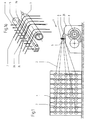
- threads 2 are drawn off from the bobbins 3 of a slip gate 4 in a known way in a slip system 1.
- the threads are brought together in a comb 5 with comb needles 6 before they run over a deflection roller 7 and / or an upstream rod 7a, which can be designed as a dedusting blowpipe, and are wound onto a winding body 8.
- the comb 5 or the comb needles 6 is intended to ensure that the threads 2 are wound onto the winding body 8 in parallel and at approximately the same distance.
- adjacent threads sometimes come together and connect with their protruding textile fibers or even jump over each other at the point of impact on the rod 7a and / or the deflection roller 7 and / or on the winding body 8, as is shown schematically by the threads 2a, 2b in FIG. 1a.
- This can obviously occur both in systems with the deflection roller 7 and in other arrangements in which e.g. threads guided in parallel can be fed directly from a guide arrangement 5, 6 to a winding body 8.
- the guide arrangement is also evidently not limited to the use of a comb 5. In practice, guide arrangements with eyelet boards or other spacers are known or can be used.
- the slip system is operated and controlled from a control panel 20 in a known manner, the control panel also has a control device for controlling the switching off and starting of the slip system 1 and all of its units.
- a holding device 9 is provided in the space between the comb 5 and the deflecting roller 7, which has a holding element designed as a rod 10 running transversely to the threads 2.
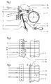
- the rod 10 can be raised from a first position I to a second position II on a movement path 11 indicated by dashed lines.
- the threads 2 are raised and brought into a tensioned position 2 ', being tensioned over the rod 10 and being fixed in the process.
- this fixation takes place directly next to the comb needles 6, so that the minimum distance determined by the thickness of the comb needles 6 also remains between the two threads 2a and b which are connected to one another in the region of the deflection roller 7.
- the rod 10 is shifted in the same direction with the conveyed threads 2 in the direction of arrow A (FIG. 3) towards the deflecting roller 7 into position III (FIGS. 2 and 4) by turning the axis 12 again.
- the distance a fixed by means of the rod 10 is maintained and the threads 2a, 2b are transferred to the deflection roller 7 at this distance.
- the connection of the threads 2a, 2b is removed again and no winding errors are to be feared in the course of operation.
- the rod 10 is now moved back to the starting position I according to FIG. 2 by further rotation of the axis 12.
- a second rod is indicated by 10a.
- this rod can be moved over the threads 2 along a movement path 11a. It can thereby be achieved that the rod 10 and the rod 10a are guided against each other in the position 2, whereby the threads 2 are fixed in a non-positive or positive manner between the two rods 10, 13 or 10a and 13 in this position.
- the fixation of the threads 2 can be additionally secured if fixation by pretensioning by means of a rod 10 alone is not sufficient to fix the threads 2 accordingly.
- the holding device 9 is driven by a motor 18.
- the motor 18 is fed with control signals by a control device 19.
- the control device 19 can be controlled by the control device for the slip system 1 arranged in the control panel 20 in such a way that the holding device 9 is automatically brought into position II, i.e. after the system 1 has been switched off, but in any case before the system 1 is restarted is activated.
- the control device 19 and / or the holding device 9 can also be activated manually and also during the run.
- the holding device 9 has a cross bar 10 as a holding element, the surface of which is provided with thread guides 13.
- the thread guides 13 consist of wedge-shaped curved comb elements, the tips of which are each aligned with the comb needles 6.
- FIG. 6 schematically shows the rod 10 in a position analogous to position I according to FIG. 2.
- the threads 2a, 2b are connected to one another analogously to FIG. 3 and are therefore on both sides of the comb needle 6 separating them.
- the tips of the thread guides 13 slide between the individual threads 2.
- the threads are thus held and fixed at a distance from one another which is wider than the thickness of the comb needles 6 and which is due to the distance between the thread guides on the rod 10 is determined.
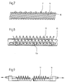
- FIG. 7 shows an exemplary embodiment in which a holding element, likewise designed as a rod 10, is provided with grooves 14 which fix the threads 2 at the distance defined by the combing needles 6.
- Figure 8 shows an embodiment in which a support rod 15 is provided as a holding element, in which displaceable fastening elements 15a are arranged.
- the fastening elements 15a carry hinge-like thread guides 13, the distance and angle of inclination of which can be adjusted by moving the fastening elements 15a.
- the thread guides can be adapted to the distance between the comb needles 6 of a comb 5.
- FIG. 9 shows an exemplary embodiment in which a support arrangement 16 is provided as the holding element, which supports a spiral spring 17.
- the carrier arrangement can be set wider or narrower, as a result of which the spiral spring 17 is tensioned to a greater or lesser extent and with which the distance between the individual spring courses can also be adapted to the distance between the comb needles 6 of a comb 5.
Landscapes
- Engineering & Computer Science (AREA)
- Textile Engineering (AREA)
- Preliminary Treatment Of Fibers (AREA)
- Looms (AREA)
- Guides For Winding Or Rewinding, Or Guides For Filamentary Materials (AREA)
Applications Claiming Priority (2)
| Application Number | Priority Date | Filing Date | Title |
|---|---|---|---|
| CH3447/92 | 1992-11-06 | ||
| CH344792 | 1992-11-06 |
Publications (2)
| Publication Number | Publication Date |
|---|---|
| EP0596834A1 true EP0596834A1 (fr) | 1994-05-11 |
| EP0596834B1 EP0596834B1 (fr) | 1996-05-22 |
Family
ID=4256151
Family Applications (1)
| Application Number | Title | Priority Date | Filing Date |
|---|---|---|---|
| EP19930810755 Expired - Lifetime EP0596834B1 (fr) | 1992-11-06 | 1993-10-29 | Dispositif et méthode pour la séparation des fils guidés parallèlement |
Country Status (3)
| Country | Link |
|---|---|
| EP (1) | EP0596834B1 (fr) |
| DE (1) | DE59302679D1 (fr) |
| ES (1) | ES2087700T3 (fr) |
Cited By (2)
| Publication number | Priority date | Publication date | Assignee | Title |
|---|---|---|---|---|
| EP2049717A2 (fr) * | 2006-07-10 | 2009-04-22 | Arvind Limited | Procédé et appareil d'ourdissage et procédé de teinture de fils fins fortement torsadés |
| CN110565228A (zh) * | 2019-08-09 | 2019-12-13 | 苏州优布纺织科技有限公司 | 一种纺织用定幅装置 |
Citations (3)
| Publication number | Priority date | Publication date | Assignee | Title |
|---|---|---|---|---|
| DE2544445B1 (de) * | 1975-10-04 | 1977-02-03 | Hacoba Textilmaschinen | Fadenkreuzvorrichtung fuer schaermaschinen |
| DE2608055A1 (de) * | 1976-02-27 | 1977-09-08 | Schlafhorst & Co W | Zettelkamm |
| EP0403430A1 (fr) * | 1989-06-14 | 1990-12-19 | Benninger AG | Ourdissoir avec formation de l'envergure et le peigne réglable en hauteur, procédé et fonctionnement |
-
1993
- 1993-10-29 ES ES93810755T patent/ES2087700T3/es not_active Expired - Lifetime
- 1993-10-29 EP EP19930810755 patent/EP0596834B1/fr not_active Expired - Lifetime
- 1993-10-29 DE DE59302679T patent/DE59302679D1/de not_active Expired - Fee Related
Patent Citations (3)
| Publication number | Priority date | Publication date | Assignee | Title |
|---|---|---|---|---|
| DE2544445B1 (de) * | 1975-10-04 | 1977-02-03 | Hacoba Textilmaschinen | Fadenkreuzvorrichtung fuer schaermaschinen |
| DE2608055A1 (de) * | 1976-02-27 | 1977-09-08 | Schlafhorst & Co W | Zettelkamm |
| EP0403430A1 (fr) * | 1989-06-14 | 1990-12-19 | Benninger AG | Ourdissoir avec formation de l'envergure et le peigne réglable en hauteur, procédé et fonctionnement |
Cited By (2)
| Publication number | Priority date | Publication date | Assignee | Title |
|---|---|---|---|---|
| EP2049717A2 (fr) * | 2006-07-10 | 2009-04-22 | Arvind Limited | Procédé et appareil d'ourdissage et procédé de teinture de fils fins fortement torsadés |
| CN110565228A (zh) * | 2019-08-09 | 2019-12-13 | 苏州优布纺织科技有限公司 | 一种纺织用定幅装置 |
Also Published As
| Publication number | Publication date |
|---|---|
| ES2087700T3 (es) | 1996-07-16 |
| EP0596834B1 (fr) | 1996-05-22 |
| DE59302679D1 (de) | 1996-06-27 |
Similar Documents
| Publication | Publication Date | Title |
|---|---|---|
| EP0296546A1 (fr) | Métier à filer pour la production de fils d'un ruban de fibres discontinues | |
| DE3114790C2 (fr) | ||
| DE3609719A1 (de) | Verfahren und vorrichtung zum beeinflussen der laenge und des maschenbildes von strickstuecken | |
| DE4008640A1 (de) | Spleissvorrichtung zum verbinden von faeden | |
| DE3415459C2 (de) | Fadenliefervorrichtung | |
| DE1303605C2 (de) | Vorrichtung zur garnfuehrung in einrichtungen zur permanenten kraeuselung von textilgarnen | |
| EP1209264B1 (fr) | Dispositif et procédé d'ourdissage | |
| DE3308247A1 (de) | Oe-friktionsspinnmaschine | |
| EP0460129B1 (fr) | Dispositif pour le remettage de fils de chaine | |
| EP0679741A1 (fr) | Appareil d'alimentation de ruban de fibres | |
| DE3805338A1 (de) | Verfahren und vorrichtung zum erzeugen von als vorlagespulen fuer ein zwirnen dienenden spulen | |
| EP0446625B1 (fr) | Dispositif d'enfilage et de changement de fils pour guide-fils | |
| DE3804147C2 (fr) | ||
| EP0596834B1 (fr) | Dispositif et méthode pour la séparation des fils guidés parallèlement | |
| DE3015191C2 (de) | Fadenwechselvorrichtung für Textilmaschinen, insbesondere Rundstrick- und Rundwirkmaschinen | |
| CH619192A5 (fr) | ||
| EP0039009A1 (fr) | Procédé et dispositif pour l'insertion pneumatique d'un fil de trame dans l'inséreur de trame d'un métier à tisser multiple | |
| DE4038982C2 (de) | Verfahren und Vorrichtung zum Verbinden von Fasersträngen | |
| CH673024A5 (fr) | ||
| DE2752232A1 (de) | Falschdrall-strecktexturiermaschine | |
| DD243186A3 (de) | Vorrichtung zum schaeren von gummielastischen faeden | |
| DE2556237C2 (de) | Spinnmaschinenanlage mit mehreren Offenend-Spinnmaschinen und wenigstens einem Wartungsgerät | |
| DE2635200C2 (de) | Fadenzuführeinrichtung | |
| EP4122859A1 (fr) | Tendeur de fil, poste de travail et procédé | |
| DE19628164B4 (de) | Verstellbarer Vliesführer |
Legal Events
| Date | Code | Title | Description |
|---|---|---|---|
| PUAI | Public reference made under article 153(3) epc to a published international application that has entered the european phase |
Free format text: ORIGINAL CODE: 0009012 |
|
| AK | Designated contracting states |
Kind code of ref document: A1 Designated state(s): CH DE ES IT LI |
|
| 17P | Request for examination filed |
Effective date: 19940917 |
|
| 17Q | First examination report despatched |
Effective date: 19951004 |
|
| GRAH | Despatch of communication of intention to grant a patent |
Free format text: ORIGINAL CODE: EPIDOS IGRA |
|
| GRAA | (expected) grant |
Free format text: ORIGINAL CODE: 0009210 |
|
| AK | Designated contracting states |
Kind code of ref document: B1 Designated state(s): CH DE ES IT LI |
|
| REG | Reference to a national code |
Ref country code: ES Ref legal event code: BA2A Ref document number: 2087700 Country of ref document: ES Kind code of ref document: T3 |
|
| REF | Corresponds to: |
Ref document number: 59302679 Country of ref document: DE Date of ref document: 19960627 |
|
| REG | Reference to a national code |
Ref country code: ES Ref legal event code: FG2A Ref document number: 2087700 Country of ref document: ES Kind code of ref document: T3 |
|
| ITF | It: translation for a ep patent filed | ||
| PLBE | No opposition filed within time limit |
Free format text: ORIGINAL CODE: 0009261 |
|
| STAA | Information on the status of an ep patent application or granted ep patent |
Free format text: STATUS: NO OPPOSITION FILED WITHIN TIME LIMIT |
|
| 26N | No opposition filed | ||
| PGFP | Annual fee paid to national office [announced via postgrant information from national office to epo] |
Ref country code: CH Payment date: 20030117 Year of fee payment: 10 |
|
| PG25 | Lapsed in a contracting state [announced via postgrant information from national office to epo] |
Ref country code: LI Free format text: LAPSE BECAUSE OF NON-PAYMENT OF DUE FEES Effective date: 20031031 Ref country code: CH Free format text: LAPSE BECAUSE OF NON-PAYMENT OF DUE FEES Effective date: 20031031 |
|
| REG | Reference to a national code |
Ref country code: CH Ref legal event code: PL |
|
| PGFP | Annual fee paid to national office [announced via postgrant information from national office to epo] |
Ref country code: IT Payment date: 20070915 Year of fee payment: 15 Ref country code: ES Payment date: 20071015 Year of fee payment: 15 Ref country code: DE Payment date: 20070921 Year of fee payment: 15 |
|
| PG25 | Lapsed in a contracting state [announced via postgrant information from national office to epo] |
Ref country code: IT Free format text: LAPSE BECAUSE OF NON-PAYMENT OF DUE FEES Effective date: 20081029 Ref country code: DE Free format text: LAPSE BECAUSE OF NON-PAYMENT OF DUE FEES Effective date: 20090501 |
|
| REG | Reference to a national code |
Ref country code: ES Ref legal event code: FD2A Effective date: 20081030 |
|
| PG25 | Lapsed in a contracting state [announced via postgrant information from national office to epo] |
Ref country code: ES Free format text: LAPSE BECAUSE OF NON-PAYMENT OF DUE FEES Effective date: 20081030 |