EP0597105A1 - Umlaufräderschaltgetriebe - Google Patents
Umlaufräderschaltgetriebe Download PDFInfo
- Publication number
- EP0597105A1 EP0597105A1 EP92917990A EP92917990A EP0597105A1 EP 0597105 A1 EP0597105 A1 EP 0597105A1 EP 92917990 A EP92917990 A EP 92917990A EP 92917990 A EP92917990 A EP 92917990A EP 0597105 A1 EP0597105 A1 EP 0597105A1
- Authority
- EP
- European Patent Office
- Prior art keywords
- speed change
- clutch
- brake
- gear
- hydraulic pressure
- Prior art date
- Legal status (The legal status is an assumption and is not a legal conclusion. Google has not performed a legal analysis and makes no representation as to the accuracy of the status listed.)
- Granted
Links
Images


Classifications
-
- B—PERFORMING OPERATIONS; TRANSPORTING
- B60—VEHICLES IN GENERAL
- B60W—CONJOINT CONTROL OF VEHICLE SUB-UNITS OF DIFFERENT TYPE OR DIFFERENT FUNCTION; CONTROL SYSTEMS SPECIALLY ADAPTED FOR HYBRID VEHICLES; ROAD VEHICLE DRIVE CONTROL SYSTEMS FOR PURPOSES NOT RELATED TO THE CONTROL OF A PARTICULAR SUB-UNIT
- B60W30/00—Purposes of road vehicle drive control systems not related to the control of a particular sub-unit, e.g. of systems using conjoint control of vehicle sub-units
- B60W30/18—Propelling the vehicle
- B60W30/18009—Propelling the vehicle related to particular drive situations
- B60W30/18036—Reversing
-
- B—PERFORMING OPERATIONS; TRANSPORTING
- B60—VEHICLES IN GENERAL
- B60W—CONJOINT CONTROL OF VEHICLE SUB-UNITS OF DIFFERENT TYPE OR DIFFERENT FUNCTION; CONTROL SYSTEMS SPECIALLY ADAPTED FOR HYBRID VEHICLES; ROAD VEHICLE DRIVE CONTROL SYSTEMS FOR PURPOSES NOT RELATED TO THE CONTROL OF A PARTICULAR SUB-UNIT
- B60W10/00—Conjoint control of vehicle sub-units of different type or different function
- B60W10/10—Conjoint control of vehicle sub-units of different type or different function including control of change-speed gearings
-
- B—PERFORMING OPERATIONS; TRANSPORTING
- B60—VEHICLES IN GENERAL
- B60W—CONJOINT CONTROL OF VEHICLE SUB-UNITS OF DIFFERENT TYPE OR DIFFERENT FUNCTION; CONTROL SYSTEMS SPECIALLY ADAPTED FOR HYBRID VEHICLES; ROAD VEHICLE DRIVE CONTROL SYSTEMS FOR PURPOSES NOT RELATED TO THE CONTROL OF A PARTICULAR SUB-UNIT
- B60W10/00—Conjoint control of vehicle sub-units of different type or different function
- B60W10/10—Conjoint control of vehicle sub-units of different type or different function including control of change-speed gearings
- B60W10/11—Stepped gearings
- B60W10/115—Stepped gearings with planetary gears
-
- B—PERFORMING OPERATIONS; TRANSPORTING
- B60—VEHICLES IN GENERAL
- B60W—CONJOINT CONTROL OF VEHICLE SUB-UNITS OF DIFFERENT TYPE OR DIFFERENT FUNCTION; CONTROL SYSTEMS SPECIALLY ADAPTED FOR HYBRID VEHICLES; ROAD VEHICLE DRIVE CONTROL SYSTEMS FOR PURPOSES NOT RELATED TO THE CONTROL OF A PARTICULAR SUB-UNIT
- B60W10/00—Conjoint control of vehicle sub-units of different type or different function
- B60W10/18—Conjoint control of vehicle sub-units of different type or different function including control of braking systems
-
- B—PERFORMING OPERATIONS; TRANSPORTING
- B60—VEHICLES IN GENERAL
- B60W—CONJOINT CONTROL OF VEHICLE SUB-UNITS OF DIFFERENT TYPE OR DIFFERENT FUNCTION; CONTROL SYSTEMS SPECIALLY ADAPTED FOR HYBRID VEHICLES; ROAD VEHICLE DRIVE CONTROL SYSTEMS FOR PURPOSES NOT RELATED TO THE CONTROL OF A PARTICULAR SUB-UNIT
- B60W30/00—Purposes of road vehicle drive control systems not related to the control of a particular sub-unit, e.g. of systems using conjoint control of vehicle sub-units
- B60W30/18—Propelling the vehicle
- B60W30/1819—Propulsion control with control means using analogue circuits, relays or mechanical links
-
- F—MECHANICAL ENGINEERING; LIGHTING; HEATING; WEAPONS; BLASTING
- F16—ENGINEERING ELEMENTS AND UNITS; GENERAL MEASURES FOR PRODUCING AND MAINTAINING EFFECTIVE FUNCTIONING OF MACHINES OR INSTALLATIONS; THERMAL INSULATION IN GENERAL
- F16H—GEARING
- F16H61/00—Control functions within control units of change-speed- or reversing-gearings for conveying rotary motion ; Control of exclusively fluid gearing, friction gearing, gearings with endless flexible members or other particular types of gearing
- F16H61/02—Control functions within control units of change-speed- or reversing-gearings for conveying rotary motion ; Control of exclusively fluid gearing, friction gearing, gearings with endless flexible members or other particular types of gearing characterised by the signals used
- F16H61/0202—Control functions within control units of change-speed- or reversing-gearings for conveying rotary motion ; Control of exclusively fluid gearing, friction gearing, gearings with endless flexible members or other particular types of gearing characterised by the signals used the signals being electric
- F16H61/0204—Control functions within control units of change-speed- or reversing-gearings for conveying rotary motion ; Control of exclusively fluid gearing, friction gearing, gearings with endless flexible members or other particular types of gearing characterised by the signals used the signals being electric for gearshift control, e.g. control functions for performing shifting or generation of shift signal
- F16H61/0246—Control functions within control units of change-speed- or reversing-gearings for conveying rotary motion ; Control of exclusively fluid gearing, friction gearing, gearings with endless flexible members or other particular types of gearing characterised by the signals used the signals being electric for gearshift control, e.g. control functions for performing shifting or generation of shift signal characterised by initiating reverse gearshift
-
- F—MECHANICAL ENGINEERING; LIGHTING; HEATING; WEAPONS; BLASTING
- F16—ENGINEERING ELEMENTS AND UNITS; GENERAL MEASURES FOR PRODUCING AND MAINTAINING EFFECTIVE FUNCTIONING OF MACHINES OR INSTALLATIONS; THERMAL INSULATION IN GENERAL
- F16H—GEARING
- F16H59/00—Control inputs to control units of change-speed- or reversing-gearings for conveying rotary motion
- F16H59/02—Selector apparatus
- F16H59/08—Range selector apparatus
- F16H2059/082—Range selector apparatus for different transmission modes
- F16H2059/088—Fast forward-reverse-sequence, e.g. rocking mode
-
- Y—GENERAL TAGGING OF NEW TECHNOLOGICAL DEVELOPMENTS; GENERAL TAGGING OF CROSS-SECTIONAL TECHNOLOGIES SPANNING OVER SEVERAL SECTIONS OF THE IPC; TECHNICAL SUBJECTS COVERED BY FORMER USPC CROSS-REFERENCE ART COLLECTIONS [XRACs] AND DIGESTS
- Y10—TECHNICAL SUBJECTS COVERED BY FORMER USPC
- Y10S—TECHNICAL SUBJECTS COVERED BY FORMER USPC CROSS-REFERENCE ART COLLECTIONS [XRACs] AND DIGESTS
- Y10S475/00—Planetary gear transmission systems or components
- Y10S475/90—Brake for input or output shaft
Definitions
- the present invention relates to a speed change gears system for changing over forward or rearward movement and changing a speed of a vehicle by selectively fixing sun gears, carriers and ring gears of a plurality of epicycloidal gear devices with respective clutches and, more particularly, to an epicycloidal type speed change gears system with an output shaft coupled to a brake to absorb a revolution energy which is generated in changing over forward or rearward movement of a vehicle.
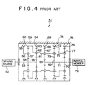
- the epicycloidal gear type speed change gears system has an F planetary gear 62 which is carried by the carrier 61 and engaged with an F sun gear 55, a ring gear 63 which is engaged with the F planetary gear 62, and an F clutch 64 for fixing the ring gear 63 to the case 59 or releasing the ring gear 63 from the case 59.
- the above speed change gears system is provided with a third planetary gear 67 which is carried by the carrier 61 and engaged with a third sun gear 65 and a third ring gear 66, a third clutch 68 which fixes or releases the third ring gear 66 to or from the case 59, and an output shaft 71 which connects the third sun gear 65, the second sun gar 69 and the first sun gear 70.
- a second planetary gear 73 which is carried by the carrier 61 and engaged with the second sun gear 69 and the second ring gear 72, a second clutch 74 which fixes or releases the second ring gear 72 to or from the case 59, and a carrier 75 which is coupled with the second ring gear 72 are provided.
- a first planetary gear 77 which is carried by the carrier 75 and engaged with the first sun gear 70 and the first ring gear 76 and a first clutch 78 which fixes the first ring gear 76 to the case 59.
- 79 denotes an inertial member of a vehicle.
- the F clutch 64 and the second clutch 74 are released immediately after a speed changing operation.
- the second clutch 74 is engaged in advance.
- the output shaft 59 is rotating due to inertia 78 of the vehicle and therefore the R carrier 56 is also rotating.
- the hydraulic pressure of the R clutch 58 is gradually increased, the rotation of the R carrier 56 is gradually slowed down and finally stopped, and the input side rotation and the output side rotation coincide with the speed changing ratio for the rearward shift 2.
- the R clutch 58 absorbs a large energy to reversely rotate the inertia member 79 of the vehicle.
- the R clutch 58 is engaged with the first clutch 78, the R ring gear 56 and the first ring gear 76 are fixed to the case 59 and other clutches are kept released.
- the R clutch 58 and the first clutch 78 are released and the second clutch 74 is engaged.
- an energy to be absorbed by the second clutch 74 is approximate to an inertia, which is a small value, of the speed change gears system 51.
- the clutch 64 is engaged. At this time, the clutch 64 absorbs a large energy to reversely rotate the inertial member 79 of the vehicle.
- the speed change gear system in accordance with the present invention is provided with a rotary wheel coupled to the output shaft, a rotation sensor for measuring a rotation speed of the rotary wheel, a controller which receives a signal from the rotation sensor and a signal from a speed change lever of the speed change gears system and a hydraulic pressure control valve for supplying and stopping a hydraulic oil to respective clutches according to the control signal from the controller, thereby controlling the oil pressure of the brake in accordance with the rotation rate of the output shaft.
- the brake absorbs the energy when forward movement is to be changed over to rearward movement, the areas of respective clutches can be reduced to be compact in dimensions.
- the brake clutch is released, the quantity of lubrication oil to be supplied to the clutches is reduced to lessen the stirring resistance of lubrication oil, thus improving the transmission efficiency.
- an epicycloidal gear type speed change gears system 1 is provided with an input shaft 3 which is driven by a driving source 2 such as an engine or a torque converter and an R sun gear and an F sun gear which are connected to the input shaft 3.
- This epicycloidal gear type speed change gears system 1 is provided with an R planetary gear 7 which is carried by an R carrier 6 and engaged with an R sun gear 5, an R clutch 8 which fixes or releases the carrier 6 to or from a case 9, a ring gear 10 which is engaged with the R planetary gear 5 and a carrier 11 which is coupled to the ring gear 10.
- a second planetary gear 23 which is carried by the carrier 11 and engaged with the second sun gear 19 and the second ring gear 22, a second clutch 24 which fixes or releases the ring gear 22 to or from the case 9, and a carrier 25 which is coupled to the second ring gear 22. It has a first planetary gear which is carried by the carrier 25 and engaged with the first sun gear 20 and the first ring gear 26 and a first clutch 28 which fixes the first ring gear 26 to the case 9.
- a brake 29 and a rotary wheel 30 are connected to the output shaft 21.
- a rotation sensor 31 for measuring the rotation rate of the rotary wheel 30, a controller 34 which receives signals from the rotation sensor 31 and a speed change lever 32 and controls a hydraulic pressure control valve 33, and piping 35, 36, 37, 38, 39 and 40 for supplying a hydraulic oil to the hydraulic cylinders of respective clutches through the hydraulic pressure control valve 33.
- the system is also provided with piping 41 for supplying a lubrication oil to the brake 29, a pilot changeover valve 42 provided in the piping 41 and piping 43 for guiding a pilot pressure to the pilot changeover valve 42. 44 denotes an inertial member of the vehicle.
- the clutches which engage with respective speed steps carry a correlation as shown with circles in Table 1.
- the F clutch 14 engages with the first clutch 28 for forward shift 1
- the F clutch 14 engages with the second clutch 24 for forward shift 2
- the F clutch 14 engages with the third clutch 18 for forward shift 3.
- the R clutch 8 engages with the first clutch 28 for rearward shift 1
- the R clutch 8 engages with the second clutch 24 for rearward shift 2
- the R clutch 8 engages with the third clutch 18 for rearward shift 3.
- step 101 a speed change signal is generated from the speed change lever 32 to the controller 34.
- Changeover from forward movement to rearward movement or from rearward movement to forward movement is determined in step 102 and, if YES is given, the hydraulic pressure control valve 33 operates to release the F clutch 14 or the R clutch 8 which is currently engaged and the operation advances to step 103.
- step 103 the hydraulic pressure control valve 33 operates and supplies a hydraulic oil to the piping 40 to actuate the brake 29. At this time, the hydraulic oil is supplied to the piping 43 and the pilot changeover valve 42 is changed over and the lubrication oil is supplied to the brake 29.
- step 106 the hydraulic pressure control valve 33 operates with a signal from the controller 34 to release a speed changeover clutch being engaged, that is, one of the first clutch 28, second clutch 24 and third clutch 18, the hydraulic pressure for the other clutch is gradually increased to cause the clutch to be engaged, and the operation advances to step 107.
- step 107 speed change is finished and the hydraulic pressure of the clutch being engaged is further boosted up to a specified pressure (step 108).
- the speed change gear system in accordance with the present invention is useful as an epicycloidal gear type speed change gears system which employs small-sized clutches and provides less stirring resistance of lubrication oil and higher transmission efficiency.
Landscapes
- Engineering & Computer Science (AREA)
- Mechanical Engineering (AREA)
- Transportation (AREA)
- Chemical & Material Sciences (AREA)
- Combustion & Propulsion (AREA)
- Automation & Control Theory (AREA)
- General Engineering & Computer Science (AREA)
- Structure Of Transmissions (AREA)
- Control Of Transmission Device (AREA)
- General Details Of Gearings (AREA)
- Gear-Shifting Mechanisms (AREA)
Applications Claiming Priority (3)
| Application Number | Priority Date | Filing Date | Title |
|---|---|---|---|
| JP3240413A JPH0560189A (ja) | 1991-08-27 | 1991-08-27 | 遊星歯車式変速機 |
| JP240413/91 | 1991-08-27 | ||
| PCT/JP1992/001058 WO1993004306A1 (fr) | 1991-08-27 | 1992-08-21 | Engrenage de changement de vitesse du type epicycloidal |
Publications (3)
| Publication Number | Publication Date |
|---|---|
| EP0597105A1 true EP0597105A1 (de) | 1994-05-18 |
| EP0597105A4 EP0597105A4 (de) | 1994-12-21 |
| EP0597105B1 EP0597105B1 (de) | 1997-12-17 |
Family
ID=17059105
Family Applications (1)
| Application Number | Title | Priority Date | Filing Date |
|---|---|---|---|
| EP92917990A Expired - Lifetime EP0597105B1 (de) | 1991-08-27 | 1992-08-21 | Umlaufräderschaltgetriebe |
Country Status (5)
| Country | Link |
|---|---|
| US (1) | US5478292A (de) |
| EP (1) | EP0597105B1 (de) |
| JP (1) | JPH0560189A (de) |
| DE (1) | DE69223627T2 (de) |
| WO (1) | WO1993004306A1 (de) |
Families Citing this family (7)
| Publication number | Priority date | Publication date | Assignee | Title |
|---|---|---|---|---|
| GB2345945B (en) * | 1998-12-23 | 2003-03-19 | Aggo Ltd | Control system for a power shuttle gearbox |
| US6663525B1 (en) | 2002-07-17 | 2003-12-16 | Case Corporation | Hydro-mechanical transmission with automatic braking capability and method of operation |
| US20040108167A1 (en) * | 2002-12-05 | 2004-06-10 | Elliott Christopher M. | Variable resistance control of a gear train oil pump |
| DE10302023A1 (de) * | 2003-01-21 | 2004-07-29 | Zf Friedrichshafen Ag | Mehrstufengetriebe |
| US20060194672A1 (en) * | 2005-01-31 | 2006-08-31 | Hitachi, Ltd. | Control device and control method of gear transmission |
| JP4889368B2 (ja) * | 2006-05-10 | 2012-03-07 | 株式会社小松製作所 | 変速機 |
| JP5326866B2 (ja) * | 2009-06-30 | 2013-10-30 | 日産自動車株式会社 | 駆動力配分装置のトランクション伝動容量制御装置 |
Family Cites Families (13)
| Publication number | Priority date | Publication date | Assignee | Title |
|---|---|---|---|---|
| DE1213689B (de) * | 1961-04-27 | 1966-03-31 | Hurth Masch Zahnrad Carl | Planetenraederwende- und -wechselgetriebe |
| US3540556A (en) * | 1968-12-05 | 1970-11-17 | Twin Disc Inc | Transmission with reversal inhibitor and automatic vehicle speed responsive brake |
| US3815445A (en) * | 1972-09-11 | 1974-06-11 | Caterpillar Tractor Co | Variable speed planetary transmission |
| AR204632A1 (es) * | 1973-09-20 | 1976-02-20 | Orchard Corp Of America | Conjunto para laminacion |
| JPS5345182Y2 (de) * | 1973-10-03 | 1978-10-28 | ||
| US4020932A (en) * | 1974-10-16 | 1977-05-03 | Caterpillar Tractor Co. | Geared steer transmission |
| JPS52133649A (en) * | 1976-04-30 | 1977-11-09 | Komatsu Ltd | Winch device |
| JPS58116849A (ja) * | 1981-12-29 | 1983-07-12 | Toshiba Corp | 電話機のインタフエ−ス回路 |
| JPS58116849U (ja) * | 1982-02-03 | 1983-08-09 | 株式会社小松製作所 | 変速機の変速制御装置 |
| US4540078A (en) * | 1983-10-27 | 1985-09-10 | Deere & Company | Clutch lube control |
| JPH0656197B2 (ja) * | 1984-12-25 | 1994-07-27 | 株式会社小松製作所 | 前進3速、後進3速遊星歯車式変速装置 |
| US4640401A (en) * | 1985-05-02 | 1987-02-03 | Deere & Company | Vehicle clutch lube control system |
| JPH0226349A (ja) * | 1988-07-14 | 1990-01-29 | Fuji Technica Inc | トラクタ用変速装置 |
-
1991
- 1991-08-27 JP JP3240413A patent/JPH0560189A/ja active Pending
-
1992
- 1992-08-21 DE DE69223627T patent/DE69223627T2/de not_active Expired - Fee Related
- 1992-08-21 EP EP92917990A patent/EP0597105B1/de not_active Expired - Lifetime
- 1992-08-21 US US08/199,241 patent/US5478292A/en not_active Expired - Fee Related
- 1992-08-21 WO PCT/JP1992/001058 patent/WO1993004306A1/ja not_active Ceased
Also Published As
| Publication number | Publication date |
|---|---|
| EP0597105A4 (de) | 1994-12-21 |
| DE69223627T2 (de) | 1998-05-07 |
| US5478292A (en) | 1995-12-26 |
| DE69223627D1 (de) | 1998-01-29 |
| WO1993004306A1 (fr) | 1993-03-04 |
| JPH0560189A (ja) | 1993-03-09 |
| EP0597105B1 (de) | 1997-12-17 |
Similar Documents
| Publication | Publication Date | Title |
|---|---|---|
| US4351409A (en) | Vehicle drive system with energy storage and retrieval | |
| US4422349A (en) | Torque transfer device for a four wheel drive vehicle | |
| US7632201B2 (en) | Hybrid drive apparatus | |
| US4699021A (en) | Integrated power system | |
| US3688607A (en) | Transmission and control | |
| US5334114A (en) | Control system for servo hydraulic pressure in vehicular automatic transmission | |
| GB2134608A (en) | Shifting automatic transmissions when vehicle coasting | |
| RU2310117C2 (ru) | Автомобильная многоступенчатая коробка передач | |
| EP0597105B1 (de) | Umlaufräderschaltgetriebe | |
| US6086501A (en) | Hydro-mechanical transmission | |
| US4501175A (en) | Speed change control unit of automatic transmission for automobiles | |
| US3851544A (en) | Transmission with torque converter and hydrostatic drives | |
| US4550629A (en) | Continuously variable speed transmission for motor vehicles | |
| EP0497038A1 (de) | Steuerungsstrategien für ein stufenlos verstellbares Getriebe mit zwei Geschwindigkeitsbereichen | |
| US6159124A (en) | Hydraulic control system for automatic transmission with energy saving logic mode | |
| KR100229234B1 (ko) | 무단변속 동력전달방법 및 그 장치 | |
| EP0047670B1 (de) | Steuereinrichtung für ein automatisches Getriebe mit Schnellgang | |
| US3248964A (en) | Transmission controls | |
| US6120406A (en) | Automatic transmission with energy saving logic and failsafe operations | |
| GB2177765A (en) | Improvements relating to automatic transmission systems | |
| JPS6235151A (ja) | 自動変速機のライン圧制御装置 | |
| KR100290390B1 (ko) | 자동차용무단변속장치 | |
| JPH05126233A (ja) | 機械油圧式変速機 | |
| JP3005864B2 (ja) | 機械油圧式伝動装置 | |
| JPS5983855A (ja) | 車輌用pto付自動変速装置の制御方法 |
Legal Events
| Date | Code | Title | Description |
|---|---|---|---|
| PUAI | Public reference made under article 153(3) epc to a published international application that has entered the european phase |
Free format text: ORIGINAL CODE: 0009012 |
|
| 17P | Request for examination filed |
Effective date: 19940223 |
|
| AK | Designated contracting states |
Kind code of ref document: A1 Designated state(s): DE GB |
|
| A4 | Supplementary search report drawn up and despatched | ||
| AK | Designated contracting states |
Kind code of ref document: A4 Designated state(s): DE GB |
|
| RHK1 | Main classification (correction) |
Ipc: B60K 41/26 |
|
| 17Q | First examination report despatched |
Effective date: 19950904 |
|
| GRAG | Despatch of communication of intention to grant |
Free format text: ORIGINAL CODE: EPIDOS AGRA |
|
| GRAG | Despatch of communication of intention to grant |
Free format text: ORIGINAL CODE: EPIDOS AGRA |
|
| GRAH | Despatch of communication of intention to grant a patent |
Free format text: ORIGINAL CODE: EPIDOS IGRA |
|
| GRAH | Despatch of communication of intention to grant a patent |
Free format text: ORIGINAL CODE: EPIDOS IGRA |
|
| GRAA | (expected) grant |
Free format text: ORIGINAL CODE: 0009210 |
|
| AK | Designated contracting states |
Kind code of ref document: B1 Designated state(s): DE GB |
|
| REF | Corresponds to: |
Ref document number: 69223627 Country of ref document: DE Date of ref document: 19980129 |
|
| PGFP | Annual fee paid to national office [announced via postgrant information from national office to epo] |
Ref country code: GB Payment date: 19980812 Year of fee payment: 7 |
|
| PLBE | No opposition filed within time limit |
Free format text: ORIGINAL CODE: 0009261 |
|
| 26N | No opposition filed | ||
| PG25 | Lapsed in a contracting state [announced via postgrant information from national office to epo] |
Ref country code: GB Free format text: LAPSE BECAUSE OF NON-PAYMENT OF DUE FEES Effective date: 19990821 |
|
| GBPC | Gb: european patent ceased through non-payment of renewal fee |
Effective date: 19990821 |
|
| PGFP | Annual fee paid to national office [announced via postgrant information from national office to epo] |
Ref country code: DE Payment date: 20000814 Year of fee payment: 9 |
|
| PG25 | Lapsed in a contracting state [announced via postgrant information from national office to epo] |
Ref country code: DE Free format text: LAPSE BECAUSE OF NON-PAYMENT OF DUE FEES Effective date: 20020501 |