EP0597239B1 - Frein de fil - Google Patents
Frein de fil Download PDFInfo
- Publication number
- EP0597239B1 EP0597239B1 EP93115994A EP93115994A EP0597239B1 EP 0597239 B1 EP0597239 B1 EP 0597239B1 EP 93115994 A EP93115994 A EP 93115994A EP 93115994 A EP93115994 A EP 93115994A EP 0597239 B1 EP0597239 B1 EP 0597239B1
- Authority
- EP
- European Patent Office
- Prior art keywords
- section
- braking
- thread
- circumferential
- abutment
- Prior art date
- Legal status (The legal status is an assumption and is not a legal conclusion. Google has not performed a legal analysis and makes no representation as to the accuracy of the status listed.)
- Expired - Lifetime
Links
- 238000003780 insertion Methods 0.000 claims abstract description 5
- 230000037431 insertion Effects 0.000 claims abstract description 5
- 238000000034 method Methods 0.000 claims description 5
- 238000004804 winding Methods 0.000 claims description 5
- 238000009941 weaving Methods 0.000 abstract description 2
- 230000005284 excitation Effects 0.000 description 9
- 230000007704 transition Effects 0.000 description 5
- 238000011161 development Methods 0.000 description 2
- 230000018109 developmental process Effects 0.000 description 2
- 230000000694 effects Effects 0.000 description 2
- 230000005415 magnetization Effects 0.000 description 2
- 230000002093 peripheral effect Effects 0.000 description 2
- 230000001133 acceleration Effects 0.000 description 1
- XAGFODPZIPBFFR-UHFFFAOYSA-N aluminium Chemical compound [Al] XAGFODPZIPBFFR-UHFFFAOYSA-N 0.000 description 1
- 229910052782 aluminium Inorganic materials 0.000 description 1
- 238000001816 cooling Methods 0.000 description 1
- 238000006073 displacement reaction Methods 0.000 description 1
- 239000000428 dust Substances 0.000 description 1
- 239000002245 particle Substances 0.000 description 1
- 230000010287 polarization Effects 0.000 description 1
Images



Classifications
-
- D—TEXTILES; PAPER
- D03—WEAVING
- D03D—WOVEN FABRICS; METHODS OF WEAVING; LOOMS
- D03D47/00—Looms in which bulk supply of weft does not pass through shed, e.g. shuttleless looms, gripper shuttle looms, dummy shuttle looms
- D03D47/34—Handling the weft between bulk storage and weft-inserting means
-
- B—PERFORMING OPERATIONS; TRANSPORTING
- B65—CONVEYING; PACKING; STORING; HANDLING THIN OR FILAMENTARY MATERIAL
- B65H—HANDLING THIN OR FILAMENTARY MATERIAL, e.g. SHEETS, WEBS, CABLES
- B65H59/00—Adjusting or controlling tension in filamentary material, e.g. for preventing snarling; Applications of tension indicators
- B65H59/10—Adjusting or controlling tension in filamentary material, e.g. for preventing snarling; Applications of tension indicators by devices acting on running material and not associated with supply or take-up devices
- B65H59/20—Co-operating surfaces mounted for relative movement
- B65H59/22—Co-operating surfaces mounted for relative movement and arranged to apply pressure to material
-
- B—PERFORMING OPERATIONS; TRANSPORTING
- B65—CONVEYING; PACKING; STORING; HANDLING THIN OR FILAMENTARY MATERIAL
- B65H—HANDLING THIN OR FILAMENTARY MATERIAL, e.g. SHEETS, WEBS, CABLES
- B65H2555/00—Actuating means
- B65H2555/20—Actuating means angular
- B65H2555/23—Actuating means angular magnetic, e.g. rotary solenoids
-
- B—PERFORMING OPERATIONS; TRANSPORTING
- B65—CONVEYING; PACKING; STORING; HANDLING THIN OR FILAMENTARY MATERIAL
- B65H—HANDLING THIN OR FILAMENTARY MATERIAL, e.g. SHEETS, WEBS, CABLES
- B65H2555/00—Actuating means
- B65H2555/20—Actuating means angular
- B65H2555/24—Servomotors
-
- B—PERFORMING OPERATIONS; TRANSPORTING
- B65—CONVEYING; PACKING; STORING; HANDLING THIN OR FILAMENTARY MATERIAL
- B65H—HANDLING THIN OR FILAMENTARY MATERIAL, e.g. SHEETS, WEBS, CABLES
- B65H2701/00—Handled material; Storage means
- B65H2701/30—Handled filamentary material
- B65H2701/31—Textiles threads or artificial strands of filaments
Definitions
- the invention relates to a device for variable braking of running threads, wires or the like, in particular for use in weft insertion on weaving machines. And a method for operating such a thread brake.
- a thread brake is known from French patent application FR-A-23 75 366.
- the thread is passed between two brake parts that can be brought together in a resilient manner.
- One of the two brake parts is fixed and not resilient and the other brake part is cushioned and movable relative to the fixed brake part, so that the thread braking can be varied in its strength by a change in the spring tension achieved as a result of the movement.
- the resilient brake part can also be spaced apart from the fixed brake part via a push rod via a push rod, so that an unbraked thread run can be achieved.
- the problem with such a thread brake is that the spring force has to be relatively strong in order to brake the thread effectively.
- the resilient braking part in order to achieve a free running of the thread, the resilient braking part must be completely lifted off the fixed braking part.
- the spring of the resilient brake part must be at least partially relaxed. This results in relatively high displacement paths of the push rod driving the resilient element. There are also limits to such an arrangement with regard to the cycle times between braking and releasing the thread, since the relaxation of the spring can no longer follow high cycle frequencies.
- the model for the invention was also the device for the different braking of running threads, which is not part of the prior art and was proposed in the non-prepublished utility model DE-U-91 13 430.
- Such a device was also disclosed in document EP-A-0 524 429 belonging to the prior art according to Article 54 (3) EPC.
- the device shown there already shows a fixed leaf spring which is acted upon by a cylindrical brake part.
- This brake part is driven by an electric motor and has a cylindrical first section, the circumferential surface of which holds the spring in a pretension in the release position of the thread run.
- a second section of the body has a peripheral section that is reduced in cross section. The thread runs between this second section and the leaf spring.
- the thread is unbraked. After a further angular amount of further rotation of the rotatable body, the thread is acted upon by the non-reduced cross-sectional circumferential section of the second section, so that the thread-braking position is achieved, the thread being clamped between the leaf spring and the cylinder surface.
- This device works in cyclical operation, with the drive motor running back and forth between two stops. In order to achieve a high clock frequency, the motor must both be driven at high acceleration and braked strongly. The use of mechanical stops for braking the motor, for example, is not optimal.
- the object of the invention is to improve the performance of such a thread brake.
- the device specified in claim 1 and the method specified in claim 6 are proposed.
- the subclaims represent advantageous developments of the invention.
- the resilient braking part no longer needs to be moved during operation to vary the braking.
- Due to the essentially cylindrical first section of circular cross-section the spring element is constantly held in a prestress, which can be varied by adjusting means.
- the second section which can also be brought into contact with the spring element, has in the circumferential direction at least one reduced cross-sectional circumferential section, which is reduced in cross-section to the extent that a window remains between the circumferential section and the spring element when it is opposite the spring element, through which the thread can be pulled off without braking.
- the shaft of the electric motor can be gradually rotated further without mechanical stops having to be provided.
- the stepper motor then only needs to be rotated by a corresponding number of steps, which is done by a corresponding number of switching impulses until the reduced cross-sectional reduced circumferential area is opposite the spring element and the thread brake position is reached.
- a preferably curved leaf spring can serve as a spring element and at the same time as a thread guide.
- Another preferred embodiment is one in which a plurality of circumferentially reduced circumferential surfaces are provided in the circumferential direction.
- Circumferential areas not reduced in cross section are provided between these reduced-area circumferential surfaces.
- a thread-free position occurs when a circumferentially reduced cross-sectional area is placed opposite the spring element, while when a circumferential area that is not reduced in cross-section is placed opposite, the thread is clamped between the counter-bearing and the spring element.
- the embodiment of the invention in which the number of steps of the stepping motor corresponds to at least twice the number of circumferentially reduced cross-sectional sections is considered to be particularly advantageous. As a result of this configuration, the stepper motor needs Transition from a braking position to a release position can only be switched by a single step.
- the number of steps of the motor is four. That means with every step the shaft of the stepper motor is turned through 90 °. In total, four steps are necessary to make one revolution of the shaft of the stepper motor.
- the invention proposes in a further development that these circumferential sections are designed as flattenings arranged transversely to the radial. The transitions to the circumferential sections which are adjacent in the circumferential direction and are not reduced in cross-section could be rounded in order to protect the thread.
- the stepper motor preferably has a magnetically polarized armature.
- this armature can be formed from a permanent magnet. The orientation of the magnet is oriented radially to the axis.
- this preferred stepper motor has an excitation coil running in the circumferential direction, which is subdivided into a number of partial windings which corresponds to the number of steps of the electric motor.
- the annular coil core of the excitation coil Associated with the individual step positions of the electric motor, has opposite pole pairs. The armature of the electric motor is oriented between these pole pairs in accordance with the polarization of the excitation coil.
- the excitation coil consists of an annular coil core with a total of four poles, each offset by 90 °, between which poles a partial winding is provided and if the armature is to be held between two of these poles by magnetic forces, the partial windings arranged between these two opposite poles are polarized in the same direction, so that a magnetization parallel to the armature magnetic field is built up. If the armature is now to be rotated one step, in this case by 90 °, the second pole pair lying transverse to the first pole pair is magnetized accordingly. Now the partial windings lying between these two poles are traversed by current in the same direction, so that a magnetic field aligned between these two magnetic poles is created.
- the method for operating a thread brake in accordance with a device includes that with each step of the stepping motor, the thread brake alternates from a braking position into a release position, starting from a braking position corresponding to a step position of the electric motor, in which a non-reduced circumferential area is opposite to the spring element, in the subsequent step of the electric motor a cross-section-reduced area is brought opposite to the spring element.
- the direction of rotation of the electric motor need not change after the transition from the braking position to the release position.
- the electric motor can always turn in the same direction operate. This enables the armature to be magnetically bonded in any step position.
- the body forming the counter bearing is rotated clockwise, step by step.
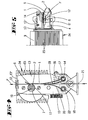
- the device shown in FIGS. 1 to 5 has an engine block 24 which is formed on the outside with cooling fins 23.
- the engine block is made of aluminum.
- a motor shaft (not shown in FIGS. 1 to 5) emerges on one side of the engine block and carries an essentially cylindrical body 2.
- the cylindrically shaped body 2 forms the counter bearing to a resilient tab 1, which thread F in the braking position between itself and the counter bearing 2 (Fig. 2) jammed.
- the tab 1 is carried by a substantially U-shaped carrier plate 13 which is screwed onto the motor housing 24 with its bottom surface. The bottom surface of the carrier 13 is penetrated by the shaft of the motor.
- Thread take-off opening 12 thread brake and thread inlet opening 21 lie almost on a straight line.
- the above-mentioned pre-brake consists of two brackets 19, 20 which are spring-loaded against one another and which are each screwed onto square axes 18, 14.
- the two tabs are screwed onto opposite surfaces of the square 14.
- All three spring elements 1, 19, 20 have essentially the same rigidity and the same width, which cover the sections 4, 5, 8 of the body 2.
- the section 8 is located between the sections 4, 5 of the body 2 which have a circular cross section.
- the section 8 has two opposite circumferential sections 6, 7 with reduced cross sections in the circumferential direction. These circumferential sections are formed by flats which are arranged essentially transversely to the radial and which, in the transition region to the sections 10, 11 of the body 2 which are not reduced in cross section, have roundings 6 ', not shown in the drawings.
- the cross-section-reducing circumferential sections 6, 7 form windows through which the thread can be drawn off without friction in the release position (cf. FIGS. 4 and 5).
- the pre-brake consisting of the leaf springs 20 and 19 can be deactivated by appropriately adjusting the setting wheel 22 and pivoting the spring tabs 19, 10, namely by spacing the resilient tab 20 from the resilient tab 19.
- the first section of the substantially cylindrical body forming the counterbearing consists of two circular sections 4, 5.
- These circular sections 4, 5 have the effect that, even in a position according to FIGS. 4 and 5, the leaf spring 1 is in a prestressed manner Location remains.
- the sections 4 and 5 run horizontally to the axis of rotation of the body 2.
- a minimal change in the position of the spring 1 takes place in the braking position (see FIGS. 2 and 3), namely when the thread between one of the circumferential sections 10 or 11 not reduced in cross section and the Tab 1 is pinched.
- the tab can be deflected by the thickness of the thread F. This is accompanied by a lifting of the tab 1 from the two Observe circular sections 4 and 5 in cross section.
- the operation of the device is as follows: The thread runs from the inlet eyelet 21 through the brake and is drawn off by the draw-off eyelet 12 and fed to a loom or the like, not shown.
- the resilient tab 1 is acted upon by the circumferential section 11 of the second section 8, which section is not reduced in cross-section, with the thread F being clamped in.
- the thread is braked in this position. In this position, the thread is not drawn off, but is held at a certain thread tension only on the part of the thread insertion eyelet 21.
- the body 2 is displaced by 90 °, as a result of which the thread's release position shown in FIGS. 4 and 5 is reached.
- the thread can now be pulled out without braking.
- the reduced-cross-sectional circumferential section 6 now has an opposite position to the leaf spring 1. Since the reduction in cross-section is many times larger than the diameter of the thread, it can be pulled off almost frictionlessly in the window formed by the reduction in cross-section. Because of the circular sections 4 and 5 which act on the tab 1 in this position, the tab 1 remains essentially in the same position.
- stepper motor which is arranged in the motor housing 23 and is designated by the reference number 9. This stepper motor has a step number of four. This means that the shaft is rotated 90 ° with each step. Each step of the stepper motor thus corresponds to a transition from a braking position to a release position or vice versa.
- the structure of the stepping motor 9 is shown schematically in FIG. 6.
- the armature 44 which is designed as a permanent magnet oriented transversely to the axis of rotation, sits on the shaft 43, which is rotatably mounted in the motor housing.
- the armature is surrounded by an annular core 30 of an excitation coil.
- the excitation coil consists of a total of four partial areas each comprising an angle of 90 °.
- Each sub-area has a sub-coil 31, 32, 33, 34 and an inwardly projecting pole 39, 40, 41, 42.
- the partial coils 31, 32, 33, 34 are arranged between the four poles 39, 40, 41, 42, each offset by 90 °.
- the ends of adjacent coils - for example those of the coils 31 and 32 - are connected to one another, the respective ends 31 "being connected to the ends 32 '.
- the connecting position of the coils 31, 32, 33, 34 form electrical connection contacts 35, 36, 37, 38 out.
- the corresponding electrical connections 35 and 37 are to be subjected to voltage current in such a way that a magnetic field aligned parallel to the magnetic field of the armature 44 is built up by the excitation coil.
- the electrical connections 36 and 38 must accordingly be supplied with voltage current, so that a magnetic field builds up between the poles 40 and 42. If a corresponding magnetic field is then built up between the opposing poles 40 and 42, the armature 44 endeavors to orient itself in this magnetic field in accordance with its magnetization. As a result, the armature 44 makes a 90 ° clockwise rotation. The north pole and south pole of the armature are thereby shifted out of the orientation to the likewise opposite poles 39 and 41.
- the armature is bound in the magnetic field built up by the excitation coil, the armature is prevented from rotating due to its angular momentum. As soon as the armature rotates beyond the equilibrium position parallel to the excitation magnetic field, the angle of the two magnetic fields causes the armature to return to its equilibrium position. This restoring force quasi forms an electromagnetic stop.
Landscapes
- Engineering & Computer Science (AREA)
- Textile Engineering (AREA)
- Looms (AREA)
- Connection Of Motors, Electrical Generators, Mechanical Devices, And The Like (AREA)
- Tension Adjustment In Filamentary Materials (AREA)
- Braking Arrangements (AREA)
- Control Of Stepping Motors (AREA)
- Yarns And Mechanical Finishing Of Yarns Or Ropes (AREA)
Claims (6)
- Dispositif pour le freinage variable de fils, filés ou similaires en déplacement, en particulier pour l'introduction du fil de trame sur les métiers à tisser, dans lequel le fil (F) se déplace entre deux pièces de freinage susceptibles d'être amenées en appui élastique l'une sur l'autre, l'une de ces pièces constituant un élément élastique et l'autre un contre-palier et l'une de ces pièces étant mobile pour faire varier l'intensité du freinage, dans lequel le contre-palier est réalisé sous la forme d'un corps (2) sensiblement cylindrique, susceptible de tourner et sollicité par l'élément élastique (1), dans lequel un tronçon (8) présente au moins une zone périphérique (6, 7) à section transversale réduite, et dans lequel est prévu un frein primaire comportant deux languettes réglables susceptibles de pivoter autour de leurs axes d'appui (18, 11).
- Dispositif pour le freinage variable de fils, filés ou similaires en déplacement, selon la revendication 1, caractérisé en ce que, dans la direction de la périphérie du corps (2), est prévue une pluralité de tronçons périphériques (6, 7) à section transversale réduite, et entre lesquels est prévu chaque fois, un tronçon périphérique (10, 11) non réduit.
- Dispositif pour le freinage variable de fils, filés ou similaires en déplacement, selon la revendication 1 ou 2 caractérisé en ce que le contre-palier est monté sur l'arbre (1) d'un moteur électrique réalisé sous la forme d'un moteur pas à pas (9) en ce que le nombre de pas du moteur électrique (9) est un multiple, de préférence le double du nombre de tronçons périphériques (6, 7) à section transversale réduite.
- Dispositif pour le freinage variable de fils, filés ou similaires en déplacement, selon l'une des revendications précédentes, caractérisé en ce que le tronçon périphérique de section transversale réduite est réalisé sous la forme d'un méplat (6, 7) disposé transversalement aux rayons.
- Dispositif pour le freinage variable de fils, filés ou similaires en déplacement, selon la revendication 3 ou 4, caractérisé en ce que le moteur pas à pas (9) comporte un induit (44) magnétique, polarisé, de préférence formé d'un aimant permanent, cet induit étant entouré de bobines d'excitation annulaires se composant d'un certain nombre de bobinages partiels (31, 32, 33, 34) qui correspondent au nombre de pas du moteur électrique, et dont le noyau forme les paires de pôles magnétiques (39, 41, 40, 42) associées aux positions de pas de l'induit.
- Procédé pour l'utilisation d'un frein à fil pour le freinage variable de fils, filés ou similaires en déplacement, en particulier pour l'introduction du fil de trame sur les métiers à tisser, dans lequel le fil (F) se déplace entre deux pièces de freinage susceptibles d'être amenées en appui élastique l'une sur l'autre, l'une de ces pièces constituant un élément élastique et l'autre un contre-palier et l'une de ces pièces de freinage étant mobile pour faire varier l'intensité du freinage, le contre-palier étant réalisé sous la forme d'un corps (2) sensiblement cylindrique, susceptible de tourner et sollicité par l'élément élastique (1), comprenant un premier tronçon (4,5) à section transversale sensiblement circulaire et un deuxième tronçon (8) présentant au moins une zone périphérique (6, 7) à section transversale réduite, le contre-palier étant monté sur l'arbre (1) d'un moteur électrique réalisé sous la forme d'un moteur pas à pas (9), selon l'une des revendications 1 à 5, caractérisé en ce qu'en tenant compte du sens de rotation du moteur, à chaque pas le frein à fil passe alternativement d'une position de freinage à une position de libération du fil, passant d'une position de freinage correspondant à une position de pas du moteur électrique, pour laquelle une zone périphérique (10, 11), qui ne présente pas de section transversale réduite, est placée en face de l'élément élastique (1), à une position au cours du pas suivant du moteur électrique, où une zone (6, 7) de section transversale réduite est amenée en face de la languette (1).
Applications Claiming Priority (2)
| Application Number | Priority Date | Filing Date | Title |
|---|---|---|---|
| DE9215226U | 1992-11-09 | ||
| DE9215226U DE9215226U1 (de) | 1992-11-09 | 1992-11-09 | Fadenbremse |
Publications (2)
| Publication Number | Publication Date |
|---|---|
| EP0597239A1 EP0597239A1 (fr) | 1994-05-18 |
| EP0597239B1 true EP0597239B1 (fr) | 1996-05-29 |
Family
ID=6885817
Family Applications (1)
| Application Number | Title | Priority Date | Filing Date |
|---|---|---|---|
| EP93115994A Expired - Lifetime EP0597239B1 (fr) | 1992-11-09 | 1993-10-04 | Frein de fil |
Country Status (6)
| Country | Link |
|---|---|
| US (1) | US5492286A (fr) |
| EP (1) | EP0597239B1 (fr) |
| JP (1) | JP3439244B2 (fr) |
| AT (1) | ATE138698T1 (fr) |
| DE (2) | DE9215226U1 (fr) |
| ES (1) | ES2053418T3 (fr) |
Families Citing this family (16)
| Publication number | Priority date | Publication date | Assignee | Title |
|---|---|---|---|---|
| BE1011089A3 (nl) * | 1997-04-07 | 1999-04-06 | Picanol Nv | Draadrem met twee remelementen. |
| SE9900665D0 (sv) * | 1999-02-23 | 1999-02-23 | Iro Patent Ag | Vorrichtung und Verfahren zum variierenden Bremseneines laufenden Fadens |
| BE1012559A3 (nl) * | 1999-03-17 | 2000-12-05 | Wiele Michel Van De Nv | Inslagdraadrem voor een weefmachine. |
| DE19919122A1 (de) | 1999-04-27 | 2000-11-02 | Iro Patent Ag Baar | Aktuator und Fadenbremse mit einem Aktuator |
| EP1095893B9 (fr) * | 1999-10-26 | 2005-05-11 | L.G.L. Electronics S.p.A. | Frein de fil de trame, plus particulièrement pour métiers à tisser |
| DE10013625A1 (de) | 2000-03-18 | 2001-09-27 | Dornier Gmbh Lindauer | Fadenbremse, insbesondere Schussfadenbremse für Webmaschinen |
| US7543610B2 (en) * | 2006-06-16 | 2009-06-09 | Sultex Ag | Thread clamp for a rapier head |
| US6755366B2 (en) * | 2002-09-30 | 2004-06-29 | Solutia Inc. | Device for direct insertion of yarn in automatic winder |
| US20040195425A1 (en) * | 2003-03-05 | 2004-10-07 | Johannes Jensen | Yarn tensioning device and arrays thereof |
| JP4003710B2 (ja) * | 2003-07-23 | 2007-11-07 | 株式会社豊田自動織機 | ジェットルームにおける緯入れ制御装置 |
| DE502006003985D1 (de) * | 2006-01-24 | 2009-07-30 | Sultex Ag | Gesteuerte Fadenbremse |
| WO2009025803A1 (fr) | 2007-08-20 | 2009-02-26 | Kevin Kremeyer | Systèmes de dépôt d'énergie, équipement et procédés permettant de modifier et de commander des ondes de choc et un écoulement supersonique |
| JP2012062186A (ja) * | 2010-09-17 | 2012-03-29 | Fuji Xerox Co Ltd | 原稿搬送装置及び画像形成装置 |
| US9908739B2 (en) * | 2012-04-24 | 2018-03-06 | Curt G. Joa, Inc. | Apparatus and method for applying parallel flared elastics to disposable products and disposable products containing parallel flared elastics |
| US10669653B2 (en) * | 2015-06-18 | 2020-06-02 | Kevin Kremeyer | Directed energy deposition to facilitate high speed applications |
| CN110817596A (zh) * | 2019-12-04 | 2020-02-21 | 芜湖航天特种电缆厂股份有限公司 | 电缆收卷前预热处理装置 |
Family Cites Families (13)
| Publication number | Priority date | Publication date | Assignee | Title |
|---|---|---|---|---|
| US2952393A (en) * | 1957-05-06 | 1960-09-13 | Charles G Newton | Yarn tension compensator |
| DE2131302A1 (de) * | 1971-06-24 | 1972-12-28 | Dornier Gmbh Lindauer | Fadenbremse fuer Textilmaschinen |
| JPS5381758A (en) * | 1976-12-27 | 1978-07-19 | Nissan Motor | Device for gripping weft on shuttleless loom |
| US4249580A (en) * | 1979-09-20 | 1981-02-10 | Rockwell International Corporation | Weft control device |
| DE3446567C1 (de) * | 1984-12-20 | 1986-05-07 | Lindauer Dornier Gmbh, 8990 Lindau | Schussfadenbremse mit stufenweise steuerbarer Bremswirkung |
| US4969489A (en) * | 1988-07-14 | 1990-11-13 | Nissan Motor Co., Ltd. | Weft threading system for fluid jet loom using the storage drum winding arm |
| BE1002841A3 (nl) * | 1989-02-16 | 1991-06-25 | Picanol N V Naamloze Vennoosch | Inrichting voor het remmen van een inslagdraad in een weefmachine. |
| US5002089A (en) * | 1990-04-02 | 1991-03-26 | Carrier Corporation | Variable area refrigerant expansion device for heating mode of a heat pump |
| BE1004140A3 (nl) * | 1990-04-17 | 1992-09-29 | Picanol Nv | Draadrem. |
| DE59105505D1 (de) * | 1990-09-10 | 1995-06-22 | Rueti Ag Maschf | Fadenbremse für Webmaschinen. |
| DE9113430U1 (de) * | 1991-07-22 | 1992-12-24 | Sobrevin Société de brevets industriels-Etablissement, Vaduz | Vorrichtung zur unterschiedlichen Bremsung laufender Fäden, Drähte o.dgl. |
| BE1005173A3 (nl) * | 1991-08-13 | 1993-05-11 | Picanol Nv | Draadrem. |
| CH686955A5 (de) * | 1992-03-16 | 1996-08-15 | Der Loepfe Ag Geb | Fadenbremseinrichtung. |
-
1992
- 1992-11-09 DE DE9215226U patent/DE9215226U1/de not_active Expired - Lifetime
-
1993
- 1993-10-04 DE DE59302741T patent/DE59302741D1/de not_active Expired - Fee Related
- 1993-10-04 ES ES93115994T patent/ES2053418T3/es not_active Expired - Lifetime
- 1993-10-04 AT AT93115994T patent/ATE138698T1/de active
- 1993-10-04 EP EP93115994A patent/EP0597239B1/fr not_active Expired - Lifetime
- 1993-10-07 US US08/133,523 patent/US5492286A/en not_active Expired - Fee Related
- 1993-11-09 JP JP30346293A patent/JP3439244B2/ja not_active Expired - Fee Related
Also Published As
| Publication number | Publication date |
|---|---|
| ES2053418T1 (es) | 1994-08-01 |
| DE9215226U1 (de) | 1994-05-11 |
| JPH06278943A (ja) | 1994-10-04 |
| JP3439244B2 (ja) | 2003-08-25 |
| EP0597239A1 (fr) | 1994-05-18 |
| ES2053418T3 (es) | 1996-07-16 |
| DE59302741D1 (de) | 1996-07-04 |
| US5492286A (en) | 1996-02-20 |
| ATE138698T1 (de) | 1996-06-15 |
Similar Documents
| Publication | Publication Date | Title |
|---|---|---|
| EP0597239B1 (fr) | Frein de fil | |
| DE69304665T2 (de) | Geschaltete Reluktanzmotoren | |
| DE69108645T2 (de) | Schrittmotor und Verfahren zum Betrieb eines solchen Motors. | |
| DE19743314A1 (de) | Bürstenloser Motor mit Permanentmagneten | |
| DE4025754A1 (de) | Permanentmagnetmotor | |
| EP0772703B1 (fr) | Dispositif de formation de lisieres pour metier a tisser | |
| DE60108317T2 (de) | Vorrichtung zur Polarisierung eines Dauermagnetläufers | |
| EP0422539A1 (fr) | Machine électrique ayant un rotor et un stator | |
| EP1071838A2 (fr) | Dispositif pour former un bord de gaze au moyen d'un moteur electrique comprenant un rotor ainsi qu'un stator logeant ce dernier | |
| DE7527207U (de) | Elektrische betaetigungsvorrichtung | |
| DE3931484C2 (fr) | ||
| DE2452131B2 (de) | Elektrischer Kleinmotor | |
| DE68906612T2 (de) | Kraftmotor. | |
| DE1932641C3 (de) | Mittels Gleichstromimpulsen wechselnder Polarität fortschaltbarer Schrittschaltmotor | |
| WO2001042079A1 (fr) | Machine electromagnetique pour un vehicule, en particulier pour une bicyclette | |
| DE102019110951B4 (de) | Verfahren und Vorrichtung zur Montage und/oder Demontage eines Permanentmagnet-Motors | |
| EP1732088B1 (fr) | Actionneur électromagnétique | |
| DE102012020434B4 (de) | Elektrischer Dämpfer für ein Kraftfahrzeug | |
| EP0151497B1 (fr) | Moteur monophasé synchrone ayant un rotor bipolaire à aimant permanent | |
| DE2929475C2 (de) | Gleichstrom-Unipolarmaschine | |
| EP0924843A1 (fr) | Dispositif pour le bobinage d'un fil | |
| EP4049356A1 (fr) | Machine électrique | |
| DE3005921A1 (de) | Monostabiles drehankersystem | |
| DE102019122603A1 (de) | Rotorvorrichtung und Statorvorrichtung für einen flachen bürstenlosen elektrischen Motor sowie flacher, bürstenloser elektrischer Motor für ein Dachsystem eines Automobils | |
| EP1509646A1 (fr) | Dispositif et procede pour sectionner un fil |
Legal Events
| Date | Code | Title | Description |
|---|---|---|---|
| PUAI | Public reference made under article 153(3) epc to a published international application that has entered the european phase |
Free format text: ORIGINAL CODE: 0009012 |
|
| AK | Designated contracting states |
Kind code of ref document: A1 Designated state(s): AT BE CH DE ES FR GB IT LI NL SE |
|
| ITCL | It: translation for ep claims filed |
Representative=s name: STUDIO JAUMANN |
|
| EL | Fr: translation of claims filed | ||
| GBC | Gb: translation of claims filed (gb section 78(7)/1977) | ||
| 17P | Request for examination filed |
Effective date: 19940727 |
|
| 17Q | First examination report despatched |
Effective date: 19950704 |
|
| GRAH | Despatch of communication of intention to grant a patent |
Free format text: ORIGINAL CODE: EPIDOS IGRA |
|
| GRAA | (expected) grant |
Free format text: ORIGINAL CODE: 0009210 |
|
| AK | Designated contracting states |
Kind code of ref document: B1 Designated state(s): AT BE CH DE ES FR GB IT LI NL SE |
|
| REF | Corresponds to: |
Ref document number: 138698 Country of ref document: AT Date of ref document: 19960615 Kind code of ref document: T |
|
| REG | Reference to a national code |
Ref country code: CH Ref legal event code: NV Representative=s name: R. A. EGLI & CO. PATENTANWAELTE |
|
| REG | Reference to a national code |
Ref country code: ES Ref legal event code: BA2A Ref document number: 2053418 Country of ref document: ES Kind code of ref document: T3 |
|
| ET | Fr: translation filed | ||
| REF | Corresponds to: |
Ref document number: 59302741 Country of ref document: DE Date of ref document: 19960704 |
|
| GBT | Gb: translation of ep patent filed (gb section 77(6)(a)/1977) |
Effective date: 19960606 |
|
| REG | Reference to a national code |
Ref country code: ES Ref legal event code: FG2A Ref document number: 2053418 Country of ref document: ES Kind code of ref document: T3 |
|
| ITF | It: translation for a ep patent filed | ||
| PG25 | Lapsed in a contracting state [announced via postgrant information from national office to epo] |
Ref country code: AT Effective date: 19961004 |
|
| PLBE | No opposition filed within time limit |
Free format text: ORIGINAL CODE: 0009261 |
|
| STAA | Information on the status of an ep patent application or granted ep patent |
Free format text: STATUS: NO OPPOSITION FILED WITHIN TIME LIMIT |
|
| 26N | No opposition filed | ||
| PGFP | Annual fee paid to national office [announced via postgrant information from national office to epo] |
Ref country code: GB Payment date: 19970805 Year of fee payment: 5 |
|
| PGFP | Annual fee paid to national office [announced via postgrant information from national office to epo] |
Ref country code: ES Payment date: 19971017 Year of fee payment: 5 |
|
| PG25 | Lapsed in a contracting state [announced via postgrant information from national office to epo] |
Ref country code: GB Free format text: LAPSE BECAUSE OF NON-PAYMENT OF DUE FEES Effective date: 19981004 |
|
| PG25 | Lapsed in a contracting state [announced via postgrant information from national office to epo] |
Ref country code: ES Free format text: LAPSE BECAUSE OF EXPIRATION OF PROTECTION Effective date: 19981005 |
|
| GBPC | Gb: european patent ceased through non-payment of renewal fee |
Effective date: 19981004 |
|
| PGFP | Annual fee paid to national office [announced via postgrant information from national office to epo] |
Ref country code: FR Payment date: 19991018 Year of fee payment: 7 |
|
| PGFP | Annual fee paid to national office [announced via postgrant information from national office to epo] |
Ref country code: SE Payment date: 19991025 Year of fee payment: 7 |
|
| PG25 | Lapsed in a contracting state [announced via postgrant information from national office to epo] |
Ref country code: SE Free format text: THE PATENT HAS BEEN ANNULLED BY A DECISION OF A NATIONAL AUTHORITY Effective date: 20001030 |
|
| REG | Reference to a national code |
Ref country code: ES Ref legal event code: FD2A Effective date: 20010201 |
|
| EUG | Se: european patent has lapsed |
Ref document number: 93115994.1 |
|
| PG25 | Lapsed in a contracting state [announced via postgrant information from national office to epo] |
Ref country code: FR Free format text: LAPSE BECAUSE OF NON-PAYMENT OF DUE FEES Effective date: 20010629 |
|
| REG | Reference to a national code |
Ref country code: FR Ref legal event code: ST |
|
| PGFP | Annual fee paid to national office [announced via postgrant information from national office to epo] |
Ref country code: BE Payment date: 20011022 Year of fee payment: 9 |
|
| PGFP | Annual fee paid to national office [announced via postgrant information from national office to epo] |
Ref country code: NL Payment date: 20011026 Year of fee payment: 9 |
|
| PGFP | Annual fee paid to national office [announced via postgrant information from national office to epo] |
Ref country code: CH Payment date: 20011102 Year of fee payment: 9 |
|
| PGFP | Annual fee paid to national office [announced via postgrant information from national office to epo] |
Ref country code: DE Payment date: 20011129 Year of fee payment: 9 |
|
| PG25 | Lapsed in a contracting state [announced via postgrant information from national office to epo] |
Ref country code: LI Free format text: LAPSE BECAUSE OF NON-PAYMENT OF DUE FEES Effective date: 20021031 Ref country code: CH Free format text: LAPSE BECAUSE OF NON-PAYMENT OF DUE FEES Effective date: 20021031 Ref country code: BE Free format text: LAPSE BECAUSE OF NON-PAYMENT OF DUE FEES Effective date: 20021031 |
|
| BERE | Be: lapsed |
Owner name: SOC. DE BREVETS INDUSTRIELS-ETABLISSEMENT *SOBREVI Effective date: 20021031 |
|
| PG25 | Lapsed in a contracting state [announced via postgrant information from national office to epo] |
Ref country code: NL Free format text: LAPSE BECAUSE OF NON-PAYMENT OF DUE FEES Effective date: 20030501 Ref country code: DE Free format text: LAPSE BECAUSE OF NON-PAYMENT OF DUE FEES Effective date: 20030501 |
|
| REG | Reference to a national code |
Ref country code: CH Ref legal event code: PL |
|
| NLV4 | Nl: lapsed or anulled due to non-payment of the annual fee |
Effective date: 20030501 |
|
| PGFP | Annual fee paid to national office [announced via postgrant information from national office to epo] |
Ref country code: IT Payment date: 20081022 Year of fee payment: 16 |
|
| PG25 | Lapsed in a contracting state [announced via postgrant information from national office to epo] |
Ref country code: IT Free format text: LAPSE BECAUSE OF NON-PAYMENT OF DUE FEES Effective date: 20091004 |