EP0597370B1 - Machines à broyer des matériaux ou à presser avec moteur électrique. - Google Patents
Machines à broyer des matériaux ou à presser avec moteur électrique. Download PDFInfo
- Publication number
- EP0597370B1 EP0597370B1 EP93117774A EP93117774A EP0597370B1 EP 0597370 B1 EP0597370 B1 EP 0597370B1 EP 93117774 A EP93117774 A EP 93117774A EP 93117774 A EP93117774 A EP 93117774A EP 0597370 B1 EP0597370 B1 EP 0597370B1
- Authority
- EP
- European Patent Office
- Prior art keywords
- switching means
- auxiliary
- motor
- switching
- main
- Prior art date
- Legal status (The legal status is an assumption and is not a legal conclusion. Google has not performed a legal analysis and makes no representation as to the accuracy of the status listed.)
- Expired - Lifetime
Links
Images

Classifications
-
- H—ELECTRICITY
- H02—GENERATION; CONVERSION OR DISTRIBUTION OF ELECTRIC POWER
- H02P—CONTROL OR REGULATION OF ELECTRIC MOTORS, ELECTRIC GENERATORS OR DYNAMO-ELECTRIC CONVERTERS; CONTROLLING TRANSFORMERS, REACTORS OR CHOKE COILS
- H02P1/00—Arrangements for starting electric motors or dynamo-electric converters
- H02P1/02—Details of starting control
- H02P1/04—Means for controlling progress of starting sequence in dependence upon time or upon current, speed, or other motor parameter
-
- B—PERFORMING OPERATIONS; TRANSPORTING
- B02—CRUSHING, PULVERISING, OR DISINTEGRATING; PREPARATORY TREATMENT OF GRAIN FOR MILLING
- B02C—CRUSHING, PULVERISING, OR DISINTEGRATING IN GENERAL; MILLING GRAIN
- B02C18/00—Disintegrating by knives or other cutting or tearing members which chop material into fragments
- B02C18/06—Disintegrating by knives or other cutting or tearing members which chop material into fragments with rotating knives
- B02C18/16—Details
- B02C18/24—Drives
-
- H—ELECTRICITY
- H02—GENERATION; CONVERSION OR DISTRIBUTION OF ELECTRIC POWER
- H02P—CONTROL OR REGULATION OF ELECTRIC MOTORS, ELECTRIC GENERATORS OR DYNAMO-ELECTRIC CONVERTERS; CONTROLLING TRANSFORMERS, REACTORS OR CHOKE COILS
- H02P23/00—Arrangements or methods for the control of AC motors characterised by a control method other than vector control
- H02P23/24—Controlling the direction, e.g. clockwise or counterclockwise
Definitions
- the invention relates to a material crushing or pressing system with a single-phase asynchronous electric motor as a drive motor with a circuit which contains main switching means for switching on the motor and auxiliary switching means for functions such as starting control, reversing the direction of rotation or the like.
- two contactors or relays with four contacts each are required to control the direction of rotation of an asynchronous single-phase AC motor with main and auxiliary winding. Since the current and the phase shift (cosine phi) of the two windings are very different, the switching devices must be designed according to the most unfavorable conditions.
- the switching devices for a 1.1 kW motor with an operating voltage of 115 V, 60 Hz, 65 A at a cosine phi of 0.7 should be able to switch. Even with a motor with an operating voltage of 230 V, 50 Hz that would still be 30 A. Switching devices that can withstand this in the long run are very complex and expensive.
- the stated 1.1 kW, 115 V, 60 Hz motor reaches 65 A with a cosine phi of 0.7 in the main winding and 5 A with a cosine phi of 0.2 in the auxiliary winding.
- the reversal can only be done via the auxiliary winding.
- CH-A-507 614 shows a reversing switching arrangement for three-phase electric motors, in which three semiconductor valves switched into the three phase lines are switched off via control relays before the electromechanical switching relay is actuated. The reverse switching is therefore without current.
- the object of the invention is to propose a material crushing or pressing system in which the construction costs for the switching means can be reduced and the operating life of the switching devices can be increased without loss of effectiveness.
- the main switching means that is to say the switch-on relay or contactor
- the switch-on relay or contactor need to switch the full current, while the switching of the auxiliary winding or, in the case of a three-phase motor, the pole switching takes place without current.
- the switching means only need to be designed for carrying current and no longer for switching. In particular, no arcing occurs during switching, which causes contact erosion or other wear.
- the auxiliary switching means are time-delayed compared to the main switching means, namely, can be actuated by electronic control means containing a time delay element. If the control power for the relays or contactors is too high to be applied directly by the electronic control means, intermediate relays can be switched on.
- a capacitor that is to say an operating capacitor, is provided in the auxiliary winding branch for controlling the auxiliary winding of the single-phase asynchronous motor.
- the delay time must be such that it is sufficient to substantially discharge the capacitance via the auxiliary winding before the auxiliary switching means is actuated.
- the discharge time can also be shortened using a discharge resistor.
- the invention makes it possible to dimension the switching means required for switching on the auxiliary winding or reversing the motor, such as relays, as simple, inexpensive switching relays, which only have to galvanically endure the current strength they carry. Powerful power relays or contactors exposed to contact erosion and wear can be limited to one main switching device. This increases the service life, in particular when there is such frequent blocking and switching in the blocked state of exposed motors and circuits for document shredders or baling presses, while at the same time reducing the construction effort.
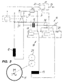
- FIG. 1 shows an asynchronous single-phase AC motor 11, the rotor of which can be driven by a main winding 12 in cooperation with an auxiliary winding in either direction of rotation. It is supplied by a mains connection 14, specifically via a main switching means 15 which is in the form of a single-pole power relay in one of the mains supply lines.
- An auxiliary winding branch 16 branches off behind the relay and contains the auxiliary winding 13, a capacitance in the form of a capacitor 17 and a switching device 18.
- the switching device contains two auxiliary switching means 19, 20 in the form of relays. While the main switching means 15 is a relay for switching high currents on and off, the relays 19, 20 only need to be designed for de-energizing the corresponding currents running through the auxiliary winding.
- the auxiliary switching means are to reverse the polarity of the auxiliary winding with two contacts and corresponding reverse polarity lines 21 connected.
- control connections which actuate the switching means 15, 19, 20 are shown in dash-dotted lines, specifically from electronic control means 22 which contain a time delay element 23.
- the pulse triggering the control is fed to the control means via a signal line 24.
- the motor 11 drives a cutting mechanism 25 of a document shredder or similar shredding device, indicated by dash-dotted lines, via a gear (not shown).
- the control procedure is as follows:
- the switchover signal via the signal line 24 first causes the power relay 15 to drop, so that the motor is de-energized. Thereafter, after a time delay via the time delay element 23, the relay 19 drops out.
- the drop-out delay is such that the capacitor 17 is above the Auxiliary winding 13 and main winding 12 has discharged.
- the relay 19 can be switched off.
- the relay 20 picks up, so that the polarity reversal of the auxiliary winding 13 is ended. This also happens without current.
- the power relay 15 is switched on again, and the motor now starts running in reverse and can thus free the cutter from the blockage. In particular when switching off from the blocked state, the highest currents would be switched with the most unfavorable cos phi, but these no longer act on the auxiliary control means 19, 20.
- the power relay 15 When the device is finally switched off, the power relay 15 first drops out again and the entire drive is de-energized. Thereafter, the relay 20 drops out with a delay.
- the dropout delay is dimensioned according to the discharge time of the capacitor 17 and the relay 20 is in turn de-energized.
- the switching pulses of the signal line 24 can be generated manually and / or automatically, for example the switching pulse depending on the current consumption (blocking state) or the like.
- FIG. 1 shows designs which are identical to that of FIG. 1, for which reason reference is made to the previous description is taken and the same reference numerals are used. The following difference exists compared to FIG. 1:
- a single-pole power relay may not be sufficient.
- a two-pole power contactor is used as auxiliary switching means 15, which in turn is controlled and actuated via an intermediate relay 26.
- the mode of operation is corresponding with the difference that instead of directly controlling the power relay 15, the intermediate relay 26 is controlled by the control means 22.
- a discharge resistor 30 is provided, which is connected between a contact of the main relay 15 and a connection 32 of the capacitor with the auxiliary switching means 19, 20. It shortens the discharge time of the capacitor 17. This also contributes to the fact that there is no arc.
- the time delay can be very short and does not interfere with the operation. In any case, it is much shorter than the normal start-up time of the motor and is practically negligible. Nevertheless, it enables currentless switching. Instead of two relays 19, 20, it would also be possible to use a single two-pole relay, although such small relays, as can be used for the auxiliary switching means, are hardly significant in terms of cost. It should also be noted that in the embodiments according to FIGS. 1 and 2, the main switching means 15 switches the main current, but with a relatively small phase shift (cosine phi close to 1) because the capacitance of the capacitor 17 almost compensates for the inductance of the main winding. In this respect, there are favorable conditions for switching under load.
Landscapes
- Engineering & Computer Science (AREA)
- Power Engineering (AREA)
- Food Science & Technology (AREA)
- Motor And Converter Starters (AREA)
- Control Of Ac Motors In General (AREA)
Claims (2)
- Installation pour déchiqueter ou comprimer des matériaux, comprenant un moteur asynchrone monophasé (11) comme moteur d'entraînement, un circuit comportant des dispositifs de commutation principaux (15) pour la mise en route du moteur (11), et des dispositifs de commutation auxiliaires (19, 20) assurant des fonctions telles que le démarrage, l'inversion du sens de marche, etc., caractérisée en ce que les dispositifs de commutation auxiliaires (19, 20) entrent en action, sans courant, et peuvent être actionnés avec une certaine temporisation par rapport aux dispositifs de commutation principaux (15), en ce que les dispositifs de commutation principaux (15) autorisent et coupent toute l'alimentation électrique du moteur (11), et les dispositifs de commutation auxiliaires (19, 20) inversent la polarité d'un enroulement auxiliaire (13) du moteur (11), pour provoquer l'inversion du sens de marche, et en ce qu'un branchement de commutation (16) d'enroulement auxiliaire, qui comporte l'enroulement auxiliaire (13), comporte également une capacité (17), et en ce que la temporisation est suffisante pour pratiquement décharger la capacité (17), par l'intermédiaire de l'enroulement auxiliaire (13) et de l'enroulement principal (12), avant que le dispositif de commutation auxiliaire (19, 20) soit actionné.
- Installation selon la revendication 1, caractérisée en ce que des dispositifs de commutation principaux et auxiliaires (15, 19, 20) sont actionnables par un dispositif de commande électronique (22) comportant un organe temporisateur (23), à l'intervention, éventuellement, d'un relais intermédiaire (26).
Applications Claiming Priority (2)
| Application Number | Priority Date | Filing Date | Title |
|---|---|---|---|
| DE4237861A DE4237861A1 (de) | 1992-11-10 | 1992-11-10 | Schaltung für einen Elektromotor, insbesondere für einen Antriebsmotor von Materialzerkleinerungs- oder Preßanlagen |
| DE4237861 | 1992-11-10 |
Publications (3)
| Publication Number | Publication Date |
|---|---|
| EP0597370A2 EP0597370A2 (fr) | 1994-05-18 |
| EP0597370A3 EP0597370A3 (fr) | 1995-01-11 |
| EP0597370B1 true EP0597370B1 (fr) | 1996-12-18 |
Family
ID=6472489
Family Applications (1)
| Application Number | Title | Priority Date | Filing Date |
|---|---|---|---|
| EP93117774A Expired - Lifetime EP0597370B1 (fr) | 1992-11-10 | 1993-11-03 | Machines à broyer des matériaux ou à presser avec moteur électrique. |
Country Status (2)
| Country | Link |
|---|---|
| EP (1) | EP0597370B1 (fr) |
| DE (2) | DE4237861A1 (fr) |
Families Citing this family (19)
| Publication number | Priority date | Publication date | Assignee | Title |
|---|---|---|---|---|
| DE19627599A1 (de) * | 1996-07-09 | 1998-01-15 | Schleicher & Co Int | Dokumentenvernichter |
| FR2758903B1 (fr) * | 1997-01-29 | 1999-02-26 | Schneider Electric Sa | Systeme inverseur de marche, notamment pour contacteur- disjoncteur |
| KR100451727B1 (ko) * | 2001-09-04 | 2004-10-08 | 엘지전자 주식회사 | 용량가변형 압축기용 모터 |
| WO2003021751A1 (fr) | 2001-09-04 | 2003-03-13 | Lg Electronics Inc. | Moteur reversible |
| DE10329157A1 (de) * | 2003-06-27 | 2005-01-20 | Demag Cranes & Components Gmbh | Antriebsanordnung, insbesondere für ein Hubwerk und/oder einen Fahrantrieb |
| US7631822B2 (en) | 2004-09-10 | 2009-12-15 | Fellowes Inc. | Shredder with thickness detector |
| US8870106B2 (en) | 2004-09-10 | 2014-10-28 | Fellowes, Inc. | Shredder with thickness detector |
| US7954737B2 (en) | 2007-10-04 | 2011-06-07 | Fellowes, Inc. | Shredder thickness with anti-jitter feature |
| US8672247B2 (en) | 2005-07-11 | 2014-03-18 | Fellowes, Inc. | Shredder with thickness detector |
| GB2451513B (en) | 2007-08-02 | 2012-04-18 | Acco Uk Ltd | A shredding machine |
| US8201761B2 (en) | 2009-01-05 | 2012-06-19 | Fellowes, Inc. | Thickness sensor based motor controller |
| US8430347B2 (en) | 2009-01-05 | 2013-04-30 | Fellowes, Inc. | Thickness adjusted motor controller |
| US8091809B2 (en) * | 2009-03-24 | 2012-01-10 | Fellowes, Inc. | Shredder with jam proof system |
| US8205815B2 (en) | 2009-05-15 | 2012-06-26 | Fellowes, Inc. | Paper alignment sensor arrangement |
| US8550387B2 (en) | 2009-06-18 | 2013-10-08 | Tai Hoon K. Matlin | Restrictive throat mechanism for paper shredders |
| US8678305B2 (en) | 2009-06-18 | 2014-03-25 | Fellowes, Inc. | Restrictive throat mechanism for paper shredders |
| US8382019B2 (en) | 2010-05-03 | 2013-02-26 | Fellowes, Inc. | In-rush current jam proof sensor control |
| US8511593B2 (en) | 2010-05-28 | 2013-08-20 | Fellowes, Inc. | Differential jam proof sensor for a shredder |
| CN103127990A (zh) * | 2011-11-24 | 2013-06-05 | 上海震旦办公设备有限公司 | 自定义扭矩碎纸机负载校正 |
Family Cites Families (4)
| Publication number | Priority date | Publication date | Assignee | Title |
|---|---|---|---|---|
| DE1128523B (de) * | 1959-12-29 | 1962-04-26 | Licentia Gmbh | Anordnung zur Steuerung der Drehrichtung eines Drehstrommotors mit Hilfe zweier Drehstromschuetze |
| CH507614A (de) * | 1969-03-14 | 1971-05-15 | Carl Maier & Cie Elek Sche Sch | Umkehrschaltanordnung für dreiphasige Motoren |
| DE3612788A1 (de) * | 1986-04-16 | 1986-09-11 | Alois Zettler Elektrotechnische Fabrik GmbH, 8000 München | Ueberlastungsschutz fuer geraet zum zerkleinern von blattfoermigem material |
| DE4107837C2 (de) * | 1991-03-12 | 1997-03-13 | Schleicher & Co Int | Dokumentenvernichter |
-
1992
- 1992-11-10 DE DE4237861A patent/DE4237861A1/de not_active Withdrawn
-
1993
- 1993-11-03 EP EP93117774A patent/EP0597370B1/fr not_active Expired - Lifetime
- 1993-11-03 DE DE59304815T patent/DE59304815D1/de not_active Expired - Lifetime
Also Published As
| Publication number | Publication date |
|---|---|
| DE4237861A1 (de) | 1994-05-11 |
| DE59304815D1 (de) | 1997-01-30 |
| EP0597370A2 (fr) | 1994-05-18 |
| EP0597370A3 (fr) | 1995-01-11 |
Similar Documents
| Publication | Publication Date | Title |
|---|---|---|
| EP0597370A2 (fr) | Machines à broyer des matériaux ou à presser avec moteur électrique. | |
| EP3915127B1 (fr) | Disjoncteur à courant continu | |
| EP1250749A1 (fr) | Appareil de commutation electrique | |
| EP0818241A1 (fr) | Déchiqueteur de documents | |
| EP4091229A1 (fr) | Dispositif de changement, kit de rattrapage et procédé pour fournir de l'énergie électrique à une charge | |
| DE4201005C2 (de) | Schaltungsanordnung zum netzunabhängigen, aussetzerfreien Bremsen eines Reihenschlußmotors | |
| EP2865089B1 (fr) | Démarreur | |
| DE3317964A1 (de) | Hybridschuetz, damit ausruestbarer elektromagnetischer linearantrieb und verfahren zum schalten des hybridschuetzes | |
| DE3443637A1 (de) | Bremsschaltung fuer wechselstrommotoren | |
| DE2131062A1 (de) | Schaltungsanordnung zum Anschliessen eines vorgewaehlten Wechselstromgenerators an wechselstromfuehrende Hauptleitungen | |
| DE2756459C2 (fr) | ||
| DE10205951A1 (de) | Steuerungsanordnung für mit elektrischer Niederspannung betriebene, mit Netzfreischaltung versehene netzabhängig gespeiste Geräte | |
| DE743280C (de) | Motorisch unmittelbar angetriebene Regeleinrichtung fuer Stufentransformatoren | |
| DE831409C (de) | Schaltung fuer elektrische Antreibe von Weichen, Signalen und aehnlichen Einrichtungen in Stellwerken mit elektrischen Verschluessen | |
| DE10057156A1 (de) | Verfahren und Schaltungsanordnung zum Einschalten einr Leistungsendstufe | |
| DE719447C (de) | Elektromagnetisches Rueckstromrelais zur Verwendung in Schutzeinrichtungen fuer elektrische Anlagen mit parallelarbeitenden Maschinen | |
| DE1515603A1 (de) | Schalteranordnung zum Ein- und Ausschalten eines wechselstromgespeisten Verbrauchers | |
| DE2802788C3 (de) | Schaltungsanordnung zum Schalten von Schaltern in Schaltfeldern bei ausfallender und wiederkehrender Spannung | |
| DE102024108637A1 (de) | Stellantrieb der Automatisierungstechnik | |
| EP2405567A1 (fr) | Commutation destinée au fonctionnement d'un dispositif de levage | |
| DE1921250C3 (de) | Schutzschaltungsanordnung für einen Elektromotor, insbesondere für einen Drehstrommotor | |
| DE417635C (de) | Einrichtung zum selbsttaetigen Zu- und Abschalten von Umformergruppen | |
| AT402457B (de) | Schutzschaltung für einen drehstrommotor | |
| DE518945C (de) | Einrichtung zur Steuerung von mehreren zu einer Gruppe vereinigten Elektromotoren ineiner bestimmten Aufeinanderfolge | |
| DE647066C (de) | Sicherheitsschaltung fuer eine elektrische Licht- oder Kraftverbrauchsanlage |
Legal Events
| Date | Code | Title | Description |
|---|---|---|---|
| PUAI | Public reference made under article 153(3) epc to a published international application that has entered the european phase |
Free format text: ORIGINAL CODE: 0009012 |
|
| AK | Designated contracting states |
Kind code of ref document: A2 Designated state(s): DE FR GB IT |
|
| PUAL | Search report despatched |
Free format text: ORIGINAL CODE: 0009013 |
|
| AK | Designated contracting states |
Kind code of ref document: A3 Designated state(s): DE FR GB IT |
|
| 17P | Request for examination filed |
Effective date: 19950126 |
|
| RAP1 | Party data changed (applicant data changed or rights of an application transferred) |
Owner name: SCHLEICHER & CO. INTERNATIONAL AKTIENGESELLSCHAFT |
|
| 17Q | First examination report despatched |
Effective date: 19950919 |
|
| GRAG | Despatch of communication of intention to grant |
Free format text: ORIGINAL CODE: EPIDOS AGRA |
|
| GRAH | Despatch of communication of intention to grant a patent |
Free format text: ORIGINAL CODE: EPIDOS IGRA |
|
| GRAH | Despatch of communication of intention to grant a patent |
Free format text: ORIGINAL CODE: EPIDOS IGRA |
|
| GRAA | (expected) grant |
Free format text: ORIGINAL CODE: 0009210 |
|
| AK | Designated contracting states |
Kind code of ref document: B1 Designated state(s): DE FR GB IT |
|
| PG25 | Lapsed in a contracting state [announced via postgrant information from national office to epo] |
Ref country code: IT Free format text: LAPSE BECAUSE OF FAILURE TO SUBMIT A TRANSLATION OF THE DESCRIPTION OR TO PAY THE FEE WITHIN THE PRESCRIBED TIME-LIMIT;WARNING: LAPSES OF ITALIAN PATENTS WITH EFFECTIVE DATE BEFORE 2007 MAY HAVE OCCURRED AT ANY TIME BEFORE 2007. THE CORRECT EFFECTIVE DATE MAY BE DIFFERENT FROM THE ONE RECORDED. Effective date: 19961218 Ref country code: GB Effective date: 19961218 Ref country code: FR Effective date: 19961218 |
|
| REF | Corresponds to: |
Ref document number: 59304815 Country of ref document: DE Date of ref document: 19970130 |
|
| EN | Fr: translation not filed | ||
| GBV | Gb: ep patent (uk) treated as always having been void in accordance with gb section 77(7)/1977 [no translation filed] |
Effective date: 19961218 |
|
| PLBE | No opposition filed within time limit |
Free format text: ORIGINAL CODE: 0009261 |
|
| 26N | No opposition filed | ||
| PGFP | Annual fee paid to national office [announced via postgrant information from national office to epo] |
Ref country code: DE Payment date: 20101119 Year of fee payment: 18 |
|
| REG | Reference to a national code |
Ref country code: DE Ref legal event code: R119 Ref document number: 59304815 Country of ref document: DE Effective date: 20130601 |
|
| PG25 | Lapsed in a contracting state [announced via postgrant information from national office to epo] |
Ref country code: DE Free format text: LAPSE BECAUSE OF NON-PAYMENT OF DUE FEES Effective date: 20130601 |