EP0597403A1 - Dispositif d'alimentation de papier - Google Patents
Dispositif d'alimentation de papier Download PDFInfo
- Publication number
- EP0597403A1 EP0597403A1 EP93118012A EP93118012A EP0597403A1 EP 0597403 A1 EP0597403 A1 EP 0597403A1 EP 93118012 A EP93118012 A EP 93118012A EP 93118012 A EP93118012 A EP 93118012A EP 0597403 A1 EP0597403 A1 EP 0597403A1
- Authority
- EP
- European Patent Office
- Prior art keywords
- paper
- supplying
- voltage
- width
- deck
- Prior art date
- Legal status (The legal status is an assumption and is not a legal conclusion. Google has not performed a legal analysis and makes no representation as to the accuracy of the status listed.)
- Withdrawn
Links
- 238000001514 detection method Methods 0.000 claims description 5
- 238000010586 diagram Methods 0.000 description 9
- 238000010276 construction Methods 0.000 description 7
- 238000007796 conventional method Methods 0.000 description 1
- 238000000034 method Methods 0.000 description 1
- 230000001105 regulatory effect Effects 0.000 description 1
Images





Classifications
-
- B—PERFORMING OPERATIONS; TRANSPORTING
- B65—CONVEYING; PACKING; STORING; HANDLING THIN OR FILAMENTARY MATERIAL
- B65H—HANDLING THIN OR FILAMENTARY MATERIAL, e.g. SHEETS, WEBS, CABLES
- B65H1/00—Supports or magazines for piles from which articles are to be separated
-
- B—PERFORMING OPERATIONS; TRANSPORTING
- B65—CONVEYING; PACKING; STORING; HANDLING THIN OR FILAMENTARY MATERIAL
- B65H—HANDLING THIN OR FILAMENTARY MATERIAL, e.g. SHEETS, WEBS, CABLES
- B65H2511/00—Dimensions; Position; Numbers; Identification; Occurrences
- B65H2511/10—Size; Dimensions
Definitions
- the present invention relates to a paper-supplying device provided in an image-forming apparatus, a printer and the like.
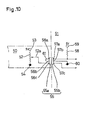
- a variable resistor 52 changing a resistance value in an interlocked relation with a paper-width-setting mechanism on a side of a paper-supplying deck 50 is connected between a constant-voltage power source 53 of for example 5 V and a ground 54 and connected with one pin 56c of a member 55a on said side of said deck where a sliding tap 52a of said variable resistor 52 constitutes a drawer-type connector 55, as shown in Fig. 10.
- one pin 57c corresponding to a pin 56c of a body-side member 55b constituting said drawer-type connector 55 is connected with an input port of a controller (not shown) on a side of a body 51.
- said resistance value of the variable resistor 52 in short a resistance from said sliding tap 52a to said ground 54, is converted into a voltage to be put in said controller through the connector 55 as a datum of a paper-width set by means of said paper-setting mechanism, whereby a width of a paper carried on a paper-carrying portion of the paper-supplying deck 50 is confirmed on a side of said body 51 under the condition that the paper-supplying deck 50 is mounted on a paper-supplying portion of the body 51, in short said deck-side member 55a of the drawer-type connector 55 is connected with said body-side member 55b.
- one pin 57a of the body-side member 55b constituting the drawer-type connector 55 is connected with a constant-voltage power source 59 of for example 5 V through a pull-up resistance 58 and a separate input port of the controller.
- the other pin 57b of the body-side member 55b is connected with a ground 60.
- two pins 56a, 56b of the deck-side member 55a corresponding to two pins 57a, 57b are connected with each other through a short- circuit line 61.
- a ground voltage in short 0 V
- a power source voltage in short 5 V
- a paper-supplying deck mounted so as to be put in and out from a paper-supplying portion of a body is provided with a sensor for detecting a size of a paper carried thereon and a paper-supplying operation is conducted in correspondence to said size of said paper detected by means of said sensor.
- the detection of the size of the paper it is necessary to detect the sizes in two directions, that is the direction of width and the longitudinal direction.
- the size in the direction of width is discriminated for 6 kinds of paper, that is B6, A5, B5R, B5 and A4, while, also as for the typical papers of inch-measure, it is required that the size in the direction of width is discriminated for 3 kinds of paper, that is 5.5 x 8.5, 8.5 x 11 R and 8.5 x 11.
- the size in the longitudinal direction of the typical papers is absolutely determined depending upon the size in the direction of width in many cases.
- the discrimination of the paper of B4 from the paper of B5 and the paper of A4 from the paper A3 can be conducted by confirming "Yes or No" on a rear portion of the paper by means of the sensor arranged at an appointed position in the longitudinal direction. This is equally true also in case of the typical papers of inch-measure.
- a lead switch, a photointerrupter, a slide-type variable resistor and the like are used as the sensor while in the detection of the size in the longitudinal direction, said lead switch, said photointerrupter and the like are used as the sensor.
- said paper-supplying device provided with a paper-supplying deck having a paper-carrying portion with a paper-width-setting mechanism and a variable resistor changing a resistance value in an interlocked relation with said paper-width-setting mechanism to put out a paper-width-detecting voltage in dependence upon said resistance value adapted to be put in and put out from a paper-supplying portion of a body, whereby electrically connecting a side of said paper-supplying deck with a side of said body through a drawer-type connector, is characterized in that a limit voltage-avoiding resistance, which prevents said paper-width-detecting voltage from amounting to a power source voltage even though said resistance value of said variable resistor became the maximum value, on said side of said paper-supplying deck, is connected with the variable resistor in series, while, on said side of said body, a pull up resistance is connected with said connector to discriminate a voltage in the connector on the side of the body between a voltage when the paper-supplying deck is mounted and a voltage when the paper-
- the paper-width-detecting voltage put in a controller on the side of the body from the variable resistor on the side of the paper-supplying deck through the drawer-type connector becomes lower than said power source voltage under the condition that the paper-supplying deck is mounted on said paper-supplying portion of the body while a voltage put in said controller on the side of the body becomes equal to the power source voltage under the condition that the paper-supplying deck is not mounted on the paper-supplying portion of the body, so that it can be discriminated from a difference of these voltages in level in the controller whether the paper-supplying deck is mounted on the paper-supplying portion of the body or not.
- the drawer-type connector with separate pins for detecting that the paper-supplying deck is mounted on the paper-supplying portion of the body and the controller on the side of the body with a separate input port for putting in the mounting-detecting signal and thus the number of pins of the drawer-type connector and the number of input ports of the controller can be reduced, whereby reducing the cost.
- a limit voltage-avoiding resistance which prevents the paper-width-detecting voltage from amounting to a ground voltage even though the resistance value of the variable resistor became the minimum value, on the side of the paper-supplying deck, may be connected with the variable resistor in series, while, on the side of the body, a pull down resistance may be connected with the connector on the side of the body.
- the paper-width-detecting voltage put in the controller on the side of the body from the variable resistor on the side of the paper-supplying deck through the drawer-type connector exceeds the ground voltage under the condition that the paper-supplying deck is mounted on the paper-supplying portion of the body while a voltage put in the controller on the side of the body becomes equal to the ground voltage under the condition that the paper-supplying deck is not mounted on the paper-supplying portion of the body and also in this case it can be discriminated from a difference of said voltage in level whether the paper-supplying deck is mounted on the paper-supplying portion of the body in the paper-supplying device or not.
- a paper-supplying device provided with a paper-supplying box carrying papers having a paper-width-setting mechanism, a variable resistor changing a resistance value thereof in an interlocked relation with said paper-width-setting mechanism to put a paper-width-detecting voltage corresponding to said resistance value and a switch for use in a detection of a size in the longitudinal direction for detecting a rear portion of said papers carried on said paper-supplying box is characterized in that a resistance larger than the total resistance of said variable resistor is connected in series with the variable resistor and said switch is connected in parallel with said larger resistance so that said paper-width-detecting voltage put out from the variable resistor may be put in a controller as a signal used also as an information of a size in the longitudinal direction.
- a difference is produced between the paper-width-detecting voltage put out from the variable resistor when said rear portion of the paper carried on a paper-supplying deck does not act upon the switch and that put out from the variable resistor when the rear portion of the paper acts upon the switch in level, and, in said controller receiving said difference through one input port, the size in the longitudinal direction can be discriminated on the basis of the difference. Accordingly, a number of input ports in the controller can be reduced and thus a program for discriminating the sizes of the papers in the controller can be simplified.
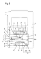
- FIG. 2 is a side sectional view roughly showing a front loading-type image-forming apparatus to which the first invention is applied.
- reference numeral 1 designates a body of said image-forming apparatus of which paper-supplying portion 1 a is provided with a plurality of paper-supplying decks 2 so as to be put therein and thereout in a multi-stepped manner from a front side of said body 1.
- Said paper-supplying decks 2 are provided with a paper-carrying portion 3 having a paper-width-setting mechanism 4 and a paper-supplying roller 5 for supplying said paper-supplying portion 1 a of the body 1 with a paper P carried on said paper-carrying portion 3 carried thereon.
- the body 1 is electrically connected with the paper-supplying decks 2 through a drawer-type connector 6. That is to say, a deck-side member 6a and a body-side member 6b constituting said drawer-type connector 6 are connected with each other under the condition that the paper-supplying deck 2 is mounted on said paper-supplying portion 1 a of the body 1 and separated from each other when the paper-supplying deck 2 is demounted.
- Fig. 3 is a perspective view roughly showing the paper-carrying portion 3 of the paper-supplying deck 2.
- reference numeral 7 designates a paper-carrying plate provided with a pair of paper-end-regulating plates 8, 8 constituting said paper-width-setting mechanism 4 arranged oppositely and movably in the back and forth direction before and behind in the moving direction Q of the paper-supplying deck 2.
- the respective paper end-regulating plates 8, 8 are provided with racks 9, 9 extending in the back and forth direction formed at lower ends thereof so that the other paper end-regulating plate 8 may move in an interlocked relation with a movement of one paper end-regulating plate 8 by engaging said racks 9, 9 with a pinion 10 pivoted below said paper-carrying plate 7.
- variable resistor 11 is arranged in the moving direction of the paper end-regulating plate 8 below said paper-carrying plate 7 and a sliding tap 11 (refer to Fig. 1) of said variable resistor 11 is connected with a lower end of one paper end-regulating plate 8 through a connecting member 12, whereby a resistance value of the variable resistor 11 is variably set in an interlocked relation with a movement of the paper end-regulating plates 8, 8, in short a width-setting operation of the paper-width-setting mechanism 4.
- Fig. 1 is a circuit diagram showing an electric connecting structure between the variable resistor 11 on the side of the paper-supplying deck 2 and a controller 13 on the side of the body 1.
- the variable resistor 11 and an upper limit voltage-suppressing resistance 16 are connected in series between a constant-voltage power source 14 of 5 V and a ground 15, that is said resistance 16 and the variable resistor 11 are connected in the order described from the side of said constant-voltage power source 14, and said sliding tap 11 a of the variable resistor 11 is connected with said deck-side member 6a constituting the drawer-type connector 6.
- the upper limit voltage-suppressing resistance 16 is a resistance for making a voltage put out from the sliding tap 11 a lower than a voltage (5 V) of a voltage of the constant-voltage power source 14 even if said resistance value of the variable resistor 11 becomes maximum, in short a resistance value R x between the sliding tap 11 a and said ground 15 becomes equal to a total resistance value R s of the variable resistor 11.
- a constant-voltage power source 17 of 5 V is connected with said body-side member 6b constituting the drawer-type connector 6 through a pull up resistance 18 and the body-side member 6b is connected with one analog input port of said controller 13.
- a resistance value R 2 of said pull up resistance 18 is set so as to be sufficiently large as compared with a resistance value R 1 of the upper limit voltage-suppressing resistance 16 and said total resistance value R s , that is so that the following relation (1) may hold good.
- the controller 13 consists of a microcomputer and a RAM 19 for memorizing various kinds of data is connected with the controller 13.
- a voltage V 1in of the body-side member 6b is expressed by the following expression (2) on the basis of the expression (1).
- R x represents a resistance value from the sliding tap 11 a to a ground-side terminal in the variable resistor 11
- R 1 represents a resistance value of the upper limit voltage-suppressing resistance 16
- R s represents a total resistance value of the variable resistor 11.
- the voltage V 1in put in the controller 13 from the body-side member 6b under the condition that the paper-supplying deck 2 is mounted on the paper-supplying portion 1a of the body 1, in short the paper-width-detecting signal, is always low in level as compared with the voltage V 1out ( ⁇ 5 V) put in said analog input port of the controller 13 from the body-side member 6b under the condition that the paper-supplying deck 2 is not mounted on the paper-supplying portion 1 a of the body 1.
- V 1out ⁇ 5 V
- a plurality of paper-width standard data corresponding to the paper-widths of the respective typical papers P for comparing a paper-width-detecting signal V in therewith to judge to which paper-width said signal corresponds are previously written in said RAM 19 in an assembling step. That is to say, when said paper standard data are written in, the paper-width-detecting signals V 1in1 , V 1in2 , ⁇ put in the controller 13 through the drawer-type connector 6 are written in the RAM 19 as a data map shown in Fig.
- Fig. 5 is a circuit diagram showing a second preferred embodiment of the first invention.
- the variable resistor 11 and a lower limit voltage-rising resistance 21 used in place of the upper limit voltage-suppressing resistance 16 in the above described first preferred embodiment are connected in series between the constant-voltage power source 14 and the ground 15, that is said resistance 21 and the variable resistor 11 are connected in the order described from the side of the ground 15.
- a pull down resistance 23 is connected between the body-side member 6b constituting the drawer-type connector 6 and the ground 15 in place of the pull up resistance 18 in the first preferred embodiment.
- a resistance value R 4 of said pull down resistance 23 is set so as to be sufficiently large as compared with a resistance value R 3 of the lower limit voltage-rising resistance 21 and the total resistance value R s of the variable resistor 11, that is, so that the following relation (5) may hold good.
- a voltage V 2out of the body-side member 6b constituting the drawer-type connector 6 is expressed by the following expression:
- FIG. 7 is a side sectional view roughly showing a front loading-type image-forming apparatus to which the second invention is applied.
- reference numeral 31 designates a body of said image-forming apparatus of which paper-supplying portion 31 a is provided with a plurality of paper-supplying decks 32 so as to be put therein and thereout in a multi-stepped manner from a front side of said body 31.
- Said paper-supplying decks 32 are provided with a paper-carrying portion 33 having a paper-width-setting mechanism 34 and a paper-supplying roller 35 for supplying said paper-supplying portion 31 a of the body 31 with a paper P carried on said paper-carrying portion 33 carried thereon.
- the body 31 is electrically connected with the paper-supplying decks 32 through a drawer-type connector 36. That is to say, a deck-side member 36a and a body-side member 36b constituting said drawer-type connector 36 are connected with each other under the condition that the paper-supplying deck 32 is mounted on said paper-supplying portion 31 a of the body 31 and separated from each other when the paper-supplying deck 32 is demounted.
- Fig. 8 is a perspective view roughly showing the paper-carrying portion 33 of the paper-supplying deck 32.
- reference numeral 37 designates a paper-carrying plate provided with a pair of paper-end-regulating plates 38, 38 constituting said paper-width-setting mechanism 34 arranged oppositely and movably in the back and forth direction before and behind in the moving direction Q of the paper-supplying deck 32.
- the respective paper end-regulating plates 38, 38 are provided with racks 39, 39 extending in the back and forth direction formed at lower ends thereof so that the other paper end-regulating plate 38 may move in an interlocked relation with a movement of one paper end-regulating plate 38 by engaging said racks 39, 39 with a pinion 40 pivoted below said paper-carrying plate 37.
- variable resistor 41 is arranged in the moving direction of the paper end-regulating plate 38 below said paper-carrying plate 37 and a sliding tap 41 a (refer to Fig. 6) of said variable resistor 41 is connected with a lower end of one paper end-regulating plate 38 through a connecting member 42, whereby a resistance value of the variable resistor 41 is variably set in an interlocked relation with a movement of the paper end-regulating plates 38, 38, in short a width-setting operation of the paper-width-setting mechanism 34.
- a longitudinal size-detecting switch 43 for discriminating the typical paper of centimeter-measure of B4 from that of B5 and that of A3 from that of A4 is arranged in the downstream side of the paper-width-setting mechanism 34 in a direction crossing at right angles with said moving direction Q of the paper-supplying deck 32, in short a paper-supplying direction R.
- the switch 43 is an always closed switch which is pushed down by said rear portions of the papers P carried on the paper-carrying portion 33 to be switched off and switched on when not pushed down.
- Fig. 6 is a circuit diagram showing an electric connecting structure between the side of the paper-supplying deck 32 and a controller 44 consisting of a microcomputer included on the side of the body 31.
- the drawer-type connector 6 is omitted.
- a resistance 47, the variable resistor 41 and a resitance 48 are connected in series between a constant-voltage power source 45 of 5 V and a ground 46, that is said resistance 47, the variable resistor 41 and said resistance 48 are connected in the order described from the side of said constant-voltage power source 45, the switch 43 being connected in parallel with the resistance 48, and a sliding tap 41 a of the variable resistor 41 being connected with an analog input port of said controller 44.
- a resistance value R 22 of the resistance 48 is set to be larger than a total resistance value R s2 of the variable resistor 41 so that a level of a voltage put out from said sliding tap 41 a when the switch 43 is switched off may be always higher than that when the switch 43 is switched on.
- R 22 is set to be larger than R s2 so that the following expression (13) may hold good, so that the width-direction size-detecting voltage V OFFB4 in the case where the papers P are B4, as shown in Fig. 9, is higher than the width-direction size-detecting voltage V ONA4 in the case where the papers P are A4 and also the width-direction size-detecting voltage V OFFA3 in the case where the papers P are A3 is higher than V ONA4 .
- the controller 44 can discriminate not only the papers of B4 from the papers of B5 but also the papers of A3 from the papers of A4.
- the paper-supplying device according to the present invention can be applied also to the image-forming apparatus in which the paper-width-setting mechanism 34 and the longitudinal size-detecting switch 43 are carried on a usual paper-supplying cassette provided with no paper-supplying roller.
Landscapes
- Engineering & Computer Science (AREA)
- Mechanical Engineering (AREA)
- Sheets, Magazines, And Separation Thereof (AREA)
Applications Claiming Priority (4)
| Application Number | Priority Date | Filing Date | Title |
|---|---|---|---|
| JP4322498A JP2622922B2 (ja) | 1992-11-07 | 1992-11-07 | 給紙装置 |
| JP4322497A JP2666054B2 (ja) | 1992-11-07 | 1992-11-07 | 給紙装置 |
| JP322498/92 | 1992-11-07 | ||
| JP322497/92 | 1992-11-07 |
Publications (1)
| Publication Number | Publication Date |
|---|---|
| EP0597403A1 true EP0597403A1 (fr) | 1994-05-18 |
Family
ID=26570838
Family Applications (1)
| Application Number | Title | Priority Date | Filing Date |
|---|---|---|---|
| EP93118012A Withdrawn EP0597403A1 (fr) | 1992-11-07 | 1993-11-05 | Dispositif d'alimentation de papier |
Country Status (2)
| Country | Link |
|---|---|
| US (1) | US5332208A (fr) |
| EP (1) | EP0597403A1 (fr) |
Cited By (1)
| Publication number | Priority date | Publication date | Assignee | Title |
|---|---|---|---|---|
| GB2307468A (en) * | 1995-11-25 | 1997-05-28 | Samsung Electronics Co Ltd | Sheet pile holders |
Families Citing this family (13)
| Publication number | Priority date | Publication date | Assignee | Title |
|---|---|---|---|---|
| JP3099213B2 (ja) * | 1994-01-14 | 2000-10-16 | 京セラミタ株式会社 | シート部材供給カセットを具備する画像生成機 |
| US5826156A (en) * | 1996-02-28 | 1998-10-20 | Minolta Co., Ltd. | Image forming apparatus |
| US5927702A (en) * | 1996-07-11 | 1999-07-27 | Canon Kabushiki Kaisha | Sheet feeder and image forming apparatus using the same |
| US5940106A (en) * | 1997-01-31 | 1999-08-17 | Hewlett-Packard Company | Resistive media size sensing system |
| KR100208397B1 (ko) * | 1997-02-13 | 1999-07-15 | 윤종용 | 팩시밀리의 원고크기 감지장치 |
| EP1149362A1 (fr) * | 1999-02-02 | 2001-10-31 | Cashcode Company Inc. | Dispositif de centrage de billets de banque pour un dispositif de validation |
| US6775514B2 (en) * | 2002-01-11 | 2004-08-10 | Xerox Corporation | Substrate size monitoring system for use in copier/printers |
| JP4781173B2 (ja) | 2005-06-29 | 2011-09-28 | キヤノン株式会社 | シートサイズ検知装置 |
| KR101324185B1 (ko) * | 2006-11-27 | 2013-11-06 | 삼성전자주식회사 | 화상형성장치 및 그 전원제어방법 |
| CN102030196A (zh) * | 2009-09-29 | 2011-04-27 | 株式会社东芝 | 堆纸器、图像形成装置、横向偏移检测方法 |
| KR101456788B1 (ko) * | 2013-06-25 | 2014-10-31 | 주식회사 엘지씨엔에스 | 매체 보관함 감지 장치 및 매체 처리 장치 |
| JP5987070B2 (ja) * | 2015-01-30 | 2016-09-06 | 京セラドキュメントソリューションズ株式会社 | 給紙装置及び画像形成装置 |
| US9533842B1 (en) * | 2016-05-31 | 2017-01-03 | Lexmark International, Inc. | Systems for sensing sheet restraint position |
Citations (5)
| Publication number | Priority date | Publication date | Assignee | Title |
|---|---|---|---|---|
| EP0310060A2 (fr) * | 1987-09-30 | 1989-04-05 | Fujitsu Limited | Dispositif d'alimentation des feuilles |
| JPH01117137A (ja) * | 1987-10-28 | 1989-05-10 | Minolta Camera Co Ltd | 画像形成装置 |
| JPH0345374A (ja) * | 1989-07-13 | 1991-02-26 | Fujitsu Ltd | 用紙サイズ設定方式 |
| JPH03120126A (ja) * | 1989-10-03 | 1991-05-22 | Brother Ind Ltd | 記録装置 |
| JPH0439218A (ja) * | 1990-05-31 | 1992-02-10 | Toshiba Corp | 画像形成装置 |
Family Cites Families (2)
| Publication number | Priority date | Publication date | Assignee | Title |
|---|---|---|---|---|
| JPS6061425A (ja) * | 1983-09-10 | 1985-04-09 | Ricoh Co Ltd | 複写機の紙サイズ検知装置 |
| JPS63185730A (ja) * | 1987-01-26 | 1988-08-01 | Minolta Camera Co Ltd | 給紙カセツト |
-
1993
- 1993-10-19 US US08/137,977 patent/US5332208A/en not_active Expired - Lifetime
- 1993-11-05 EP EP93118012A patent/EP0597403A1/fr not_active Withdrawn
Patent Citations (5)
| Publication number | Priority date | Publication date | Assignee | Title |
|---|---|---|---|---|
| EP0310060A2 (fr) * | 1987-09-30 | 1989-04-05 | Fujitsu Limited | Dispositif d'alimentation des feuilles |
| JPH01117137A (ja) * | 1987-10-28 | 1989-05-10 | Minolta Camera Co Ltd | 画像形成装置 |
| JPH0345374A (ja) * | 1989-07-13 | 1991-02-26 | Fujitsu Ltd | 用紙サイズ設定方式 |
| JPH03120126A (ja) * | 1989-10-03 | 1991-05-22 | Brother Ind Ltd | 記録装置 |
| JPH0439218A (ja) * | 1990-05-31 | 1992-02-10 | Toshiba Corp | 画像形成装置 |
Non-Patent Citations (4)
| Title |
|---|
| PATENT ABSTRACTS OF JAPAN vol. 13, no. 340 (M - 857) 31 July 1989 (1989-07-31) * |
| PATENT ABSTRACTS OF JAPAN vol. 15, no. 186 (M - 1112) 14 May 1991 (1991-05-14) * |
| PATENT ABSTRACTS OF JAPAN vol. 15, no. 318 (M - 1146) 14 August 1991 (1991-08-14) * |
| PATENT ABSTRACTS OF JAPAN vol. 16, no. 214 (M - 1251) 20 May 1992 (1992-05-20) * |
Cited By (3)
| Publication number | Priority date | Publication date | Assignee | Title |
|---|---|---|---|---|
| GB2307468A (en) * | 1995-11-25 | 1997-05-28 | Samsung Electronics Co Ltd | Sheet pile holders |
| GB2307468B (en) * | 1995-11-25 | 2000-03-22 | Samsung Electronics Co Ltd | Sheet feeder |
| CN1090585C (zh) * | 1995-11-25 | 2002-09-11 | 三星电子株式会社 | 页纸供给装置 |
Also Published As
| Publication number | Publication date |
|---|---|
| US5332208A (en) | 1994-07-26 |
Similar Documents
| Publication | Publication Date | Title |
|---|---|---|
| EP0597403A1 (fr) | Dispositif d'alimentation de papier | |
| JP2785545B2 (ja) | 用紙収容装置の用紙サイズ検知装置 | |
| US20110081154A1 (en) | Apparatus for detecting connector connection state | |
| JPS63185730A (ja) | 給紙カセツト | |
| JPH03147629A (ja) | 記録紙長検知装置 | |
| US5343142A (en) | Sheet size detection device | |
| US5105078A (en) | Apparatus and method for detecting overlapped paper sheet feed | |
| US5238238A (en) | Paper feeding cassette case in image forming apparatus | |
| EP0873954B1 (fr) | Dispositif de différenciation de format de feuille | |
| JP2622922B2 (ja) | 給紙装置 | |
| US11548744B2 (en) | Image forming apparatus | |
| EP0344676B1 (fr) | Dispositif pour la formation d'images | |
| JPH0338171B2 (fr) | ||
| JP2666054B2 (ja) | 給紙装置 | |
| JPH0626984B2 (ja) | 給紙カセツト構造 | |
| JP3334001B2 (ja) | 用紙サイズ検出装置および該検出機能を有した給紙カセット装置 | |
| JPH06271094A (ja) | 用紙積載装置 | |
| JPH0345374A (ja) | 用紙サイズ設定方式 | |
| EP3726296B1 (fr) | Système de formation d'images et appareil de formation d'images | |
| JP3337277B2 (ja) | 用紙サイズ検知装置 | |
| DE19952285B4 (de) | Bilderzeugungsvorrichtung | |
| US5311270A (en) | Paper cassette having a plurality of switches for selecting an input data port | |
| JPH061543Y2 (ja) | 用紙及びカセツト検知装置 | |
| US6118971A (en) | Original-feeding device and method capable of separating and feeding the uppermost and the lowermost original | |
| JP2610950B2 (ja) | Ohpシート複写装置 |
Legal Events
| Date | Code | Title | Description |
|---|---|---|---|
| PUAI | Public reference made under article 153(3) epc to a published international application that has entered the european phase |
Free format text: ORIGINAL CODE: 0009012 |
|
| AK | Designated contracting states |
Kind code of ref document: A1 Designated state(s): DE FR GB IT |
|
| 17P | Request for examination filed |
Effective date: 19940426 |
|
| 17Q | First examination report despatched |
Effective date: 19950906 |
|
| STAA | Information on the status of an ep patent application or granted ep patent |
Free format text: STATUS: THE APPLICATION IS DEEMED TO BE WITHDRAWN |
|
| 18D | Application deemed to be withdrawn |
Effective date: 19960117 |