EP0597421B1 - Lagerdichtungsvorrichtung und Verfahren zum Montieren einer Dichtungsscheibe - Google Patents
Lagerdichtungsvorrichtung und Verfahren zum Montieren einer Dichtungsscheibe Download PDFInfo
- Publication number
- EP0597421B1 EP0597421B1 EP93118080A EP93118080A EP0597421B1 EP 0597421 B1 EP0597421 B1 EP 0597421B1 EP 93118080 A EP93118080 A EP 93118080A EP 93118080 A EP93118080 A EP 93118080A EP 0597421 B1 EP0597421 B1 EP 0597421B1
- Authority
- EP
- European Patent Office
- Prior art keywords
- bearing
- sealing
- adhesive material
- sealing plate
- groove
- Prior art date
- Legal status (The legal status is an assumption and is not a legal conclusion. Google has not performed a legal analysis and makes no representation as to the accuracy of the status listed.)
- Expired - Lifetime
Links
- 238000007789 sealing Methods 0.000 title claims description 167
- 238000000034 method Methods 0.000 title claims description 20
- 239000000463 material Substances 0.000 claims description 79
- 239000000853 adhesive Substances 0.000 claims description 77
- 230000001070 adhesive effect Effects 0.000 claims description 77
- 239000003566 sealing material Substances 0.000 claims description 25
- 238000010438 heat treatment Methods 0.000 claims description 13
- 239000013013 elastic material Substances 0.000 claims description 9
- 239000007769 metal material Substances 0.000 claims description 7
- 229920001169 thermoplastic Polymers 0.000 claims description 6
- 239000004416 thermosoftening plastic Substances 0.000 claims description 6
- 238000001816 cooling Methods 0.000 claims description 5
- 239000011347 resin Substances 0.000 claims description 4
- 229920005989 resin Polymers 0.000 claims description 4
- 239000010410 layer Substances 0.000 description 31
- 230000002093 peripheral effect Effects 0.000 description 16
- 238000004519 manufacturing process Methods 0.000 description 7
- 239000002184 metal Substances 0.000 description 7
- 238000010276 construction Methods 0.000 description 6
- 230000004048 modification Effects 0.000 description 3
- 238000012986 modification Methods 0.000 description 3
- 230000015572 biosynthetic process Effects 0.000 description 2
- 238000010586 diagram Methods 0.000 description 2
- 230000000694 effects Effects 0.000 description 2
- 238000000465 moulding Methods 0.000 description 2
- 239000004033 plastic Substances 0.000 description 2
- 229920003023 plastic Polymers 0.000 description 2
- 238000004080 punching Methods 0.000 description 2
- 238000005549 size reduction Methods 0.000 description 2
- 238000007711 solidification Methods 0.000 description 2
- 230000008023 solidification Effects 0.000 description 2
- 229920001967 Metal rubber Polymers 0.000 description 1
- 239000012790 adhesive layer Substances 0.000 description 1
- 230000000994 depressogenic effect Effects 0.000 description 1
- 238000001035 drying Methods 0.000 description 1
- 230000002349 favourable effect Effects 0.000 description 1
- 239000004519 grease Substances 0.000 description 1
- 239000012943 hotmelt Substances 0.000 description 1
- 230000002045 lasting effect Effects 0.000 description 1
- 229920003052 natural elastomer Polymers 0.000 description 1
- 229920001194 natural rubber Polymers 0.000 description 1
- 238000010422 painting Methods 0.000 description 1
- 238000002360 preparation method Methods 0.000 description 1
- 239000002994 raw material Substances 0.000 description 1
- 230000002269 spontaneous effect Effects 0.000 description 1
- 238000005507 spraying Methods 0.000 description 1
- 229920003051 synthetic elastomer Polymers 0.000 description 1
- 239000005061 synthetic rubber Substances 0.000 description 1
Images


Classifications
-
- F—MECHANICAL ENGINEERING; LIGHTING; HEATING; WEAPONS; BLASTING
- F16—ENGINEERING ELEMENTS AND UNITS; GENERAL MEASURES FOR PRODUCING AND MAINTAINING EFFECTIVE FUNCTIONING OF MACHINES OR INSTALLATIONS; THERMAL INSULATION IN GENERAL
- F16C—SHAFTS; FLEXIBLE SHAFTS; ELEMENTS OR CRANKSHAFT MECHANISMS; ROTARY BODIES OTHER THAN GEARING ELEMENTS; BEARINGS
- F16C33/00—Parts of bearings; Special methods for making bearings or parts thereof
- F16C33/72—Sealings
- F16C33/76—Sealings of ball or roller bearings
- F16C33/78—Sealings of ball or roller bearings with a diaphragm, disc, or ring, with or without resilient members
- F16C33/784—Sealings of ball or roller bearings with a diaphragm, disc, or ring, with or without resilient members mounted to a groove in the inner surface of the outer race and extending toward the inner race
- F16C33/7843—Sealings of ball or roller bearings with a diaphragm, disc, or ring, with or without resilient members mounted to a groove in the inner surface of the outer race and extending toward the inner race with a single annular sealing disc
- F16C33/7846—Sealings of ball or roller bearings with a diaphragm, disc, or ring, with or without resilient members mounted to a groove in the inner surface of the outer race and extending toward the inner race with a single annular sealing disc with a gap between the annular disc and the inner race
-
- F—MECHANICAL ENGINEERING; LIGHTING; HEATING; WEAPONS; BLASTING
- F16—ENGINEERING ELEMENTS AND UNITS; GENERAL MEASURES FOR PRODUCING AND MAINTAINING EFFECTIVE FUNCTIONING OF MACHINES OR INSTALLATIONS; THERMAL INSULATION IN GENERAL
- F16C—SHAFTS; FLEXIBLE SHAFTS; ELEMENTS OR CRANKSHAFT MECHANISMS; ROTARY BODIES OTHER THAN GEARING ELEMENTS; BEARINGS
- F16C33/00—Parts of bearings; Special methods for making bearings or parts thereof
- F16C33/72—Sealings
- F16C33/76—Sealings of ball or roller bearings
- F16C33/78—Sealings of ball or roller bearings with a diaphragm, disc, or ring, with or without resilient members
- F16C33/7816—Details of the sealing or parts thereof, e.g. geometry, material
- F16C33/783—Details of the sealing or parts thereof, e.g. geometry, material of the mounting region
-
- F—MECHANICAL ENGINEERING; LIGHTING; HEATING; WEAPONS; BLASTING
- F16—ENGINEERING ELEMENTS AND UNITS; GENERAL MEASURES FOR PRODUCING AND MAINTAINING EFFECTIVE FUNCTIONING OF MACHINES OR INSTALLATIONS; THERMAL INSULATION IN GENERAL
- F16C—SHAFTS; FLEXIBLE SHAFTS; ELEMENTS OR CRANKSHAFT MECHANISMS; ROTARY BODIES OTHER THAN GEARING ELEMENTS; BEARINGS
- F16C33/00—Parts of bearings; Special methods for making bearings or parts thereof
- F16C33/72—Sealings
- F16C33/76—Sealings of ball or roller bearings
- F16C33/78—Sealings of ball or roller bearings with a diaphragm, disc, or ring, with or without resilient members
- F16C33/7816—Details of the sealing or parts thereof, e.g. geometry, material
- F16C33/7833—Special methods of manufacture
-
- F—MECHANICAL ENGINEERING; LIGHTING; HEATING; WEAPONS; BLASTING
- F16—ENGINEERING ELEMENTS AND UNITS; GENERAL MEASURES FOR PRODUCING AND MAINTAINING EFFECTIVE FUNCTIONING OF MACHINES OR INSTALLATIONS; THERMAL INSULATION IN GENERAL
- F16C—SHAFTS; FLEXIBLE SHAFTS; ELEMENTS OR CRANKSHAFT MECHANISMS; ROTARY BODIES OTHER THAN GEARING ELEMENTS; BEARINGS
- F16C43/00—Assembling bearings
- F16C43/04—Assembling rolling-contact bearings
- F16C43/045—Mounting or replacing seals
-
- F—MECHANICAL ENGINEERING; LIGHTING; HEATING; WEAPONS; BLASTING
- F16—ENGINEERING ELEMENTS AND UNITS; GENERAL MEASURES FOR PRODUCING AND MAINTAINING EFFECTIVE FUNCTIONING OF MACHINES OR INSTALLATIONS; THERMAL INSULATION IN GENERAL
- F16J—PISTONS; CYLINDERS; SEALINGS
- F16J15/00—Sealings
- F16J15/16—Sealings between relatively-moving surfaces
- F16J15/32—Sealings between relatively-moving surfaces with elastic sealings, e.g. O-rings
- F16J15/3268—Mounting of sealing rings
-
- F—MECHANICAL ENGINEERING; LIGHTING; HEATING; WEAPONS; BLASTING
- F16—ENGINEERING ELEMENTS AND UNITS; GENERAL MEASURES FOR PRODUCING AND MAINTAINING EFFECTIVE FUNCTIONING OF MACHINES OR INSTALLATIONS; THERMAL INSULATION IN GENERAL
- F16C—SHAFTS; FLEXIBLE SHAFTS; ELEMENTS OR CRANKSHAFT MECHANISMS; ROTARY BODIES OTHER THAN GEARING ELEMENTS; BEARINGS
- F16C2226/00—Joining parts; Fastening; Assembling or mounting parts
- F16C2226/30—Material joints
- F16C2226/40—Material joints with adhesive
-
- F—MECHANICAL ENGINEERING; LIGHTING; HEATING; WEAPONS; BLASTING
- F16—ENGINEERING ELEMENTS AND UNITS; GENERAL MEASURES FOR PRODUCING AND MAINTAINING EFFECTIVE FUNCTIONING OF MACHINES OR INSTALLATIONS; THERMAL INSULATION IN GENERAL
- F16C—SHAFTS; FLEXIBLE SHAFTS; ELEMENTS OR CRANKSHAFT MECHANISMS; ROTARY BODIES OTHER THAN GEARING ELEMENTS; BEARINGS
- F16C33/00—Parts of bearings; Special methods for making bearings or parts thereof
- F16C33/72—Sealings
- F16C33/76—Sealings of ball or roller bearings
- F16C33/80—Labyrinth sealings
Definitions
- the present invention generally relates to sealing of a bearing, and more particularly, to a sealing device for the bearing and a mounting method of a sealing plate for a bearing.
- a conventional sealing plate for a bearing it is so arranged that a core metal formed by punching a metallic plate is placed in a recess or concave portion of a metal mold for molding by pouring an elastic material therein, and the bearing sealing plate formed thereby is so adapted that its forward edge diameter is slightly larger than an opening diameter of a bearing sealing groove, and a wall face of the sealing groove of an outer race or inner race of the bearing is sunken so as to force the bearing sealing plate into the sealing groove, thus causing the forward edge portion of the sealing plate to depress the wall face of the sealing groove to achieve the sealing.
- the bearing sealing plate is made of a metallic material, proper performance of the sealing plate tends to be obstructed through deformation of the bearing outer race or inner race, with a possibility of leakage of grease from the outer circumferential portion of the bearing sealing plate.
- GB-A-599 095 relates to sealed bearings comprising inner and outer bearing members or race rings having a space between them which is closed at one or each end by an annular closure member or plate bonded to an end face of or into a recess in one of the bearing members or race rings.
- DE-OS-41 35 035 relates to the lateral sealing of a bearing which comprises at least one layer of a heat-resistant plastics material, is inserted between an inner and outer race in correspondingly shaped flanges (Fig. 2) and is permanently fixed to the outer race by means of an adhesive, which also flows into a concavity in the wall of the groove defined by the flange of the outer race.
- a concave portion formed on a circumferential wall of the sealing groove allows melted adhesive material adhering to the reserve face of the bearing sealing plate or the wall facing axially outward of the sealing groove to flow in due to heating and pressurization of the bearing sealing plate inserted in the sealing groove, and by the solidification of the adhesive material which has thus been directed into the concave portion, such hardened adhesive material increases the mounting strength of said sealing plate with respect to the sealing groove so as to act as a retainer.
- a bearing with a sealing device for a bearing which generally includes a bearing outer race 1 having a sealing groove 2 including a vertical face 2a and a horizontal support face 2b, a bearing inner race 3 and a bearing sealing plate 4 constituted by an adhesive material 6 applied to one or both faces of a sealing material 5 having a ring-hole or not, and the bearing sealing plate 4 is bonded and fixed to the horizontal support face of said sealing groove 2.
- the bearing sealing plate 4 is of a flat plate, and constituted by covering the surface of the sealing material 5 with the adhesive material 6.
- the sealing material 5 is made of, for example, metal, natural or synthetic rubber, plastics and the like, and is not limited in the raw material therefor so far as it is provided with air tightness.
- the adhesive material layer 6 a material which may be bonded by heating, pressurization or known methods can be used, and although the material itself is not limited, an elastic material with adhering nature including an adhesive material of thermo-plastic property of hot-melt group is preferable.
- Fig. 2 shows one embodiment of the adhering method of the adhesive material layer 6 onto the sealing material 5 for the bearing sealing plate 4, in which the sealing material 5 drawn out of its roll 5a, and that adhesive material 6 drawn out of its roll 6a respectively are passed between a set of rollers 7 for adhesion to each other under pressure.
- the bearing sealing plates 4 of a desired size are punched out by metal dies (not shown in Fig. 2).
- Fig. 3 shows another method of producing the bearing sealing plate 4.
- the adhesive material 6b contained in a vessel 8 is melted through heating by heating means 10, e.g., an electric heater or the like, and the molten adhesive material 6b is discharged through a nozzle 9 of the vessel 8 onto the upper surface of the sealing material 5 drawn out from a roll 5b, thereby to cause the adhesive material 6b to adhere onto the surface of the sealing material 5.
- the belt-like sheet thus prepared is blanked by metal dies 11 to prepare the bearing sealing plate 4.
- the sealing plate 4 For mounting such bearing sealing plate 4 as described so far into the sealing groove 2 in the bearing outer race 1, the sealing plate 4 is fitted into the sealing groove 2, with the adhesive material layer 6 directed downwards (in Figure 1), and by contacting the adhesive material layer 6 with the support face 2b of the sealing groove 2, the sealing plate 4 is heated from above (in Figure 1) so as to melt part or all of the adhesive material layer 6, thereby to cause the sealing plate 4 to adhere to said support face 2b for subsequent cooling and fixing. (Fig. 1).
- the heating of the bearing sealing plate 4 may be effected before contact with the support face 2b of the sealing groove 2, and that the heating means for the heating of the sealing plate 4 is not limited to any specific means.
- the manufacturing method of the bearing sealing plate 4 is not limited to the above, but may, for example, be so modified as to apply the molten adhesive material onto the surface of the sealing material 5 by a sprayer or by a brush.
- the adhesive material layer on the sealing plate 4 may be so arranged to cause the adhesive material to adhere thereto by painting, spraying or other methods after punching the sealing material 5 in a desired shape.
- the sealing groove 2 is provided on the inner race 3 instead of being formed on the outer race 1, and the adhesive material layer 6 of the bearing sealing plate 4 is brought into contact with the support face of the sealing groove of the inner race 3 for adhesion by heating.
- a lip may be provided on the outer peripheral edge of the sealing plate 4 so as to contact the bearing outer race 1.
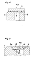
- the sealing groove 2 is not provided on the bearing outer race 1, but the sealing plate 4A prepared by causing the adhesive material layer 6 to adhere to the sealing material 5 is adapted to contact the upper surface (in Fig. 4) of the bearing outer race 1 at its side of the adhesive material layer 6, and the sealing plate 4A is heated for subsequent forced or spontaneous cooling, thereby to cause the sealing plate 4A to closely contact and to be fixed to the outer race 1.
- a clearance is provided between the upper surface (in Fig. 4) of the inner race 3 and the adhesive material layer 6 or the sealing material 5 as shown.
- the bearing sealing plate 4A in a flat disk-like shape may be modified to be a ring-like shape, and further, to be provided with a known lip in a peripheral edge of its inner hole (not shown).
- the sealing device in Fig. 4 may be further modified in such a manner that, instead of causing the sealing plate 4A to adhere to the surface of the bearing outer race 1, it may be adapted to adhere to the inner race 3. In that case, it may be so arranged to provide a lip at the outer peripheral edge portion of the bearing sealing plate, so that said lip contacts the bearing outer race.
- the configurations of the bearing sealing plate are not limited to those as shown in Fig. 1 and Fig. 4.
- the outer peripheral edge portion 13 is made of a metallic material, and its inner peripheral portion 14 is formed by an elastic material, with the adhesive material layer 6 being provided on the outer peripheral edge portion 13.
- the arrangement may be so modified that the inner peripheral portion 14 is made of a metallic material and the outer peripheral portion 13 is formed by an elastic material in the reverse order as above.
- the sealing material made of two kinds of materials may be employed as in the bearing sealing plate 4B in Fig. 5.
- the outer peripheral edge portion and the inner portion may be formed either by a metallic material or elastic material.
- the bearing sealing plate 4C as shown in Fig. 6 is of a ring-like shape, with a ring-shaped protrusion 5C being formed along an inner hole edge of the ring, and the adhesive material layer 6 is provided on the face of the sealing material 5 at its side of the protrusion 5C (excluding the under surface of the protrusion 5C) or on the outer side face of the protrusion 5C continuous on said face.
- the lip in the inner hole of the sealing plate 4C is abbreviated for brevity in the drawing.
- sealing plate 4C since the adhesive material layer 6 is not provided on the under surface of the protrusion 5C in the ring-like shape, an unused sealing plate 4C may be overlapped therewith for storing.
- sealing plate 4C it may be so modified to place the outer peripheral portion of the sealing plate 4C on the upper surface (in Fig. 6) of the bearing outer race 1 for use by adhering, without providing the sealing groove 2 on the outer race 1.
- the protrusion 5C may be provided on the outer peripheral edge of the sealing plate, instead of being provided on the ring inner hole edge.
- the bearing sealing plate 4D as shown in Fig. 7 is of a ring-shape, and includes an outer peripheral portion 17 in a horizontal plane, an intermediate portion 18 inclined upwardly from the portion 17, and an inner hole edge portion 19 extending horizontally laterally from said intermediate portion 18 as shown, with an adhesive material layer 6 is provided on the under surface of said outer peripheral portion 17.
- a lip may further be provided along the inner hole edge.
- the bearing sealing plate 4D is fitted into a sealing groove 20 of a conventional bearing outer race 1 for use, after contacting the adhesive material layer 6 on the under surface of the outer peripheral portion 17 of the fitted sealing plate 4D, with the support face 20a of the sealing groove 20, the sealing plate 4D is heated, and thereafter, cooled so as to be bonded and fixed to said support face 20a.
- the bearing sealing plate 4D is bonded and fixed onto the upper surface (in Fig. 7) of the bearing outer race 1 not provided with the sealing groove 20.
- thickness (i.e., height in Fig. 7) of the bearing outer race 1 is made thinner than that of the inner race 3.
- the sealing plates made of metallic materials there are available the sealing plates of curl type, root type and washer type, each of which, however, has a problem in the sealing performance.
- the sealing performance may be improved by providing the adhesive material layer 6 on the surfaces contacting the concave portion of the sealing groove of the outer race or the support face of the sealing groove, and by bonding the metallic sealing plate with the bearing outer race with the adhesive material.
- the layers or films may be formed through employment of the known adhesive material or elastic material with adhesive nature as the adhesive material of the adhesive material layer 6, and the adhesive material is not limited to the thermo-plastic adhesive material.
- any of the foregoing embodiments it may be so arranged to cause the adhesive material to adhere to the surface of the bearing outer race or inner race contacting the sealing plate instead of subjecting the adhesive material to adhere to the sealing plate.
- the adhesion between the bearing sealing plate and the bearing outer race or inner race is not limited to that by the heating method, but heating, pressurization or known methods therefor may be employed according to the nature of the adhesive material.
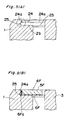
- Figs. 9(A) and 9(B) show a bearing sealing device and a method for mounting the bearing sealing plate according to the present invention.
- a sealing groove 24 including a circumferential wall 24a, a concave portion 25 and a wall 2b facing axially outward of the groove 24 is provided on the bearing outer race 1.
- the concave portion 25 is continuously or intermittently formed on the entire surface of the vertical face 24a.
- the bearing sealing plate 4F is provided with a rather thick adhesive material layer 6F of a thermo-plastic resin formed on at least one surface of a sealing material 5F.
- This adhesive material layer 6F is adapted to be slightly thicker over the entire surface or at least on the outer peripheral portion thereof.
- the sealing plate 4F is inserted into the sealing groove 24, with the adhesive material layer 6F directed downward, and thus, the adhesive material layer 6F is caused to adhere to the wall 2b of the sealing groove 24. Then, the sealing plate 4F is heated and pressurized, and part of the molten adhesive material is depressed so as to flow into the concave portion 25 provided in the vertical face 24a and to be filled therein. Subsequently, the bearing sealing plate 6F is subjected to natural or forcible cooling or drying, thereby to solidify the adhesive material.
- the protruding portion 6Fa of the adhesive material layer 6F hardened in the concave portion 25 prevents the sealing plate 4F from coming off the sealing groove 24, thus positively maintaining the mounting strength to the bearing outer race.
- the arrangement may, for example, be so modified that the sealing groove 24 is provided on the inner race 3 instead of the outer race 1, with a concave portion equivalent to the concave portion 25 being provided in said sealing groove.
- the bearing sealing plate is provided with a rather thick adhesive material layer of a thermo-plastic resin formed on at least one surface of the sealing material. This adhesive material layer is adapted to be slightly thicker over the entire surface or at least on the inner peripheral portion.
- the mounting method of the bearing sealing plate and formation of the protrusion of the adhesive layer and its effect, etc. are similar to those in the above arrangement.
- the sealing groove of the bearing outer race or inner race may be simply constituted by the circumferential wall, the concave portion and the wall facing axially outward of the groove, and the wall face of the sealing groove is not required to be curved as in the conventional constructions.
- the bearing outer race or inner race formed with the sealing groove itself may be employed, higher strength can be achieved as compared with conventional outer race or inner race.
- the hardened adhesive material in said concave portion acts as a retainer or anchor for the bearing sealing plate, thereby providing higher mounting strength of the sealing plate.
Landscapes
- Engineering & Computer Science (AREA)
- General Engineering & Computer Science (AREA)
- Mechanical Engineering (AREA)
- Sealing Of Bearings (AREA)
- Rolling Contact Bearings (AREA)
Claims (8)
- Lager mit einer Dichtungsvorrichtung, das aufweist: einen äußeren Lagerlaufring (1) und einen inneren Laufring (3), wobei einer von ihnen eine Dichtungsrille (24) mit einer Umfangswand (24a), einem in die Umfangswand vorstehenden konkaven Teil (25) und einer axial nach außen gerichteten Wand (2b) der Rille (24) hat, und eine Lagerdichtungsscheibe (4F), die aus einem Klebstoffmaterial (6F) besteht, das auf mindestens eine Seite eines Dichtungsmaterials (5F) mit oder ohne Ringloch aufgetragen wurde, wobei das Klebstoffmaterial (6F) den konkaven Teil (25) und den Spalt zwischen dem Umfang der Dichtungsscheibe (4F) und der Umfangswand (24a) der Rille (24) füllt.
- Lager nach Anspruch 1, wobei die Lagerdichtungsscheibe (4F) aus zwei Arten von Dichtungsmaterialien einschließlich einem metallischen Material und einem elastischen Material besteht.
- Lager nach einem der Ansprüche 1 oder 2, wobei der konkave Teil (25) der Dichtungsrille (24) zusammenhängend oder in Abständen über einen gesamten Umfang der Umfangswand (24a) gebildet ist.
- Lager nach einem der Ansprüche 1 bis 3, wobei das Klebstoffmaterial (6) aus einem elastischen Material mit Haftfähigkeit gefertigt ist.
- Lager nach einem der Ansprüche 1 bis 4, wobei die Klebstoffmaterialschicht (6F) überall oder in der Nachbarschaft eines äußeren Umfangs des Dichtungsmaterials (5F) dicker gemacht wird.
- Verfahren zum Montieren einer Dichtungsscheibe für ein Lager nach einem der Ansprüche 1 bis 5, das die folgenden Schritte aufweist:a) Bereitstellen einer Dichtungsrille (24) mit einer Umfangswand (24a), einem konkaven Teil (25) und einer axial nach außen gewandten Wand (2b) der Rille (24) entweder auf einem äußeren Lagerlaufring (1) oder einem inneren Laufring (3),b) Bilden einer Lagerdichtungsscheibe (4F) durch Auftragen einer aus einem thermoplastischen Kunstharz-Klebstoffmaterial gefertigten Klebstoffmaterialschicht (6F) auf mindestens eine Seite eines Dichtungsmaterials (5F) mit oder ohne Ringloch,c) In-Kontakt-Bringen der Lagerdichtungsscheibe (4F) mit der axial nach außen gewandten Wand (2b) der Dichtungsrille (24),d) Erwärmen der Lagerdichtungsscheibe (4F), um das Klebstoffmaterial (6F) zu verschmelzen, unde) Füllen des geschmolzenen Klebstoffmaterials (6F) in den konkaven Teil (25) und den Spalt zwischen dem Umfang der Dichtungsscheibe (4F) und der Umfangswand (24a) der Rille (24), indem bewirkt wird, daß das Klebstoffmaterial fließt, um dabei das Klebstoffmaterial (6F) durch natürliche oder erzwungene Kühlung zu verfestigen.
- Verfahren nach Anspruch 6, wobei die Lagerdichtungsscheibe (4F) mit der Klebstoffmaterialschicht (6F) nach unten gewandt in die Dichtungsrille (24) eingesetzt wird.
- Verfahren zum Montieren einer Dichtungsscheibe in ein Lager nach einem der Ansprüche 1 bis 5, das die folgenden Schritte aufweist:a) Bereitstellen einer Dichtungsrille (24) mit einer Umfangswand (24a), einem konkaven Teil (25) und einer axial nach außen gewandten Wand (2b) der Rille (24) entweder auf einem äußeren Lagerlaufring (1) oder einem inneren Laufring (3),b') Auftragen einer aus einem thermoplastischen Kunstharz-Klebstoffmaterial gefertigten Klebstoffmaterialschicht (6F) auf eine ganze Seite der axial nach außen gewandten Wand (2b) der Rille (24), wobei die Klebstoffmaterialschicht (6F) in der Nachbarschaft des konkaven Teils der Umfangswand (24a) oder überall dicker gemacht wird,c') Einsetzen einer aus einem Dichtungsmaterial (5F) bestehenden Lagerdichtungsscheibe (4F) in die Dichtungsrille (24), um mit der Klebstoffmaterialschicht auf der axial nach außen gewandten Wand (2b) der Rille (24) in Berührung zu kommen,d) Erwärmen der Lagerdichtungsscheibe (4F), um das Klebstoffmaterial (6F) zu verschmelzen, unde) Füllen des geschmolzenen Klebstoffmaterials (6F) in den konkaven Teil (25) und den Spalt zwischen dem Umfang der Dichtungsscheibe (4F) und der Umfangswand (24a) der Rille (24), indem bewirkt wird, daß das Klebstoffmaterial fließt, um dabei das Klebstoffmaterial (6F) durch natürliche oder erzwungene Kühlung zu verfestigen.
Applications Claiming Priority (4)
| Application Number | Priority Date | Filing Date | Title |
|---|---|---|---|
| JP32487892 | 1992-11-10 | ||
| JP324878/92 | 1992-11-10 | ||
| JP294560/93 | 1993-10-29 | ||
| JP5294560A JPH06200949A (ja) | 1992-11-10 | 1993-10-29 | 軸受用密封板の装着方法および軸受用密封装置 |
Publications (3)
| Publication Number | Publication Date |
|---|---|
| EP0597421A2 EP0597421A2 (de) | 1994-05-18 |
| EP0597421A3 EP0597421A3 (de) | 1994-10-12 |
| EP0597421B1 true EP0597421B1 (de) | 1999-02-10 |
Family
ID=26559886
Family Applications (1)
| Application Number | Title | Priority Date | Filing Date |
|---|---|---|---|
| EP93118080A Expired - Lifetime EP0597421B1 (de) | 1992-11-10 | 1993-11-08 | Lagerdichtungsvorrichtung und Verfahren zum Montieren einer Dichtungsscheibe |
Country Status (5)
| Country | Link |
|---|---|
| US (1) | US5882121A (de) |
| EP (1) | EP0597421B1 (de) |
| JP (1) | JPH06200949A (de) |
| CN (1) | CN1054908C (de) |
| DE (1) | DE69323472T2 (de) |
Families Citing this family (12)
| Publication number | Priority date | Publication date | Assignee | Title |
|---|---|---|---|---|
| US5590935A (en) * | 1995-09-29 | 1997-01-07 | Mcallister; Michael J. | In-line skate wheel cover |
| JPH11257361A (ja) * | 1998-01-08 | 1999-09-21 | Nippon Seiko Kk | 転がり軸受の密封装置 |
| US7031106B2 (en) * | 2000-02-01 | 2006-04-18 | Nsk Ltd. | Sealing member, rolling bearing, thin motor, and bearing device |
| JP2002267028A (ja) * | 2001-03-07 | 2002-09-18 | Shimano Inc | 部品組立体 |
| US8061903B2 (en) * | 2010-01-28 | 2011-11-22 | Rexnord Industries, Llc | Bearing assembly with extended maintenance interval |
| US8740464B2 (en) | 2011-11-02 | 2014-06-03 | Rexnord Industries, Llc | Bearing assembly having a floating seal |
| MX2014010770A (es) | 2012-03-08 | 2014-10-14 | Weatherford Lamb | Transductor optico con via de paso integrada. |
| WO2016145623A1 (en) * | 2015-03-18 | 2016-09-22 | The Timken Company | Fixture for installing a seal wear ring |
| DE102017107005B3 (de) | 2017-03-31 | 2018-09-13 | Schaeffler Technologies AG & Co. KG | Abgedichtetes Wälzlager |
| JP7133263B2 (ja) * | 2017-09-29 | 2022-09-08 | グローブライド株式会社 | 磁性流体シール装置及び磁性流体シール付き軸受 |
| JP7262182B2 (ja) * | 2018-05-31 | 2023-04-21 | ミネベアミツミ株式会社 | 軸受装置 |
| US12151509B2 (en) | 2020-10-12 | 2024-11-26 | Federal-Mogul Motorparts Llc | Wheel hub assembly and method of testing |
Family Cites Families (5)
| Publication number | Priority date | Publication date | Assignee | Title |
|---|---|---|---|---|
| GB599095A (en) * | 1945-09-13 | 1948-03-04 | Fischer Bearings Company Ltd | Improvements relating to sealed bearings |
| US2140672A (en) * | 1937-04-17 | 1938-12-20 | Glenn L Martin Co | Method of producing a seal |
| FR1477701A (fr) * | 1966-03-10 | 1967-04-21 | Sfim | Perfectionnements aux roulements, notamment aux roulements à bague extérieure tournante |
| JPH022526U (de) * | 1988-06-16 | 1990-01-09 | ||
| DE4135035A1 (de) * | 1991-10-23 | 1993-04-29 | Hoechst Ag | Seitliche kugellagerabkapselung und kugellager enthaltend dieselbe |
-
1993
- 1993-10-29 JP JP5294560A patent/JPH06200949A/ja active Pending
- 1993-11-08 DE DE69323472T patent/DE69323472T2/de not_active Expired - Lifetime
- 1993-11-08 EP EP93118080A patent/EP0597421B1/de not_active Expired - Lifetime
- 1993-11-10 CN CN93112940A patent/CN1054908C/zh not_active Expired - Fee Related
-
1997
- 1997-04-10 US US08/834,862 patent/US5882121A/en not_active Expired - Fee Related
Also Published As
| Publication number | Publication date |
|---|---|
| DE69323472T2 (de) | 1999-08-05 |
| CN1054908C (zh) | 2000-07-26 |
| DE69323472D1 (de) | 1999-03-25 |
| EP0597421A2 (de) | 1994-05-18 |
| CN1095800A (zh) | 1994-11-30 |
| US5882121A (en) | 1999-03-16 |
| JPH06200949A (ja) | 1994-07-19 |
| EP0597421A3 (de) | 1994-10-12 |
Similar Documents
| Publication | Publication Date | Title |
|---|---|---|
| EP0597421B1 (de) | Lagerdichtungsvorrichtung und Verfahren zum Montieren einer Dichtungsscheibe | |
| US4459092A (en) | Apparatus for integrally molding an ornament plate on a plastic body | |
| US4595117A (en) | Sealing lip for lid on thermoformed container | |
| US20040256348A1 (en) | Flex panel lid or cap | |
| US4131211A (en) | Receptacle made of thermoplastic material | |
| CA2007329C (en) | Method of forming a package | |
| US4228633A (en) | Method for manufacturing, filling and closing a receptacle made of thermoplastic material | |
| US4078287A (en) | Method of forming sealing members | |
| AU576740B2 (en) | An improved mounting cup and method of making same | |
| US4659405A (en) | Method and apparatus for making a sealing lip for lid on thermoformed container | |
| US4589886A (en) | Method of making part of a watch case | |
| EP0636820B1 (de) | Lagerdichtungsplatte und ihr Herstellungsverfahren | |
| US20120324850A1 (en) | Air Filter Element with Covered Terminal Disks | |
| US4370689A (en) | Flexible magnetic recording medium with improved reinforcement means | |
| CA1194005A (en) | Electrostatically sprayed mounting cup gasket | |
| JPH11154503A (ja) | 鉛蓄電池用端子 | |
| JP2599362Y2 (ja) | 密封装置 | |
| JP2956491B2 (ja) | 金属と合成樹脂の複合蓋とその製造装置 | |
| JP4032524B2 (ja) | 密封装置の製造方法 | |
| JPH02258320A (ja) | 芯部材を有する樹脂成形品の製造方法 | |
| JPH0748541Y2 (ja) | 隠し表示付きキャップ | |
| JPS6165914A (ja) | 軸受用密封材の製造方法 | |
| WO1997003807A3 (en) | Process of making b-pillar covers and covers produced thereby | |
| JP2000006266A (ja) | 密封材の製造方法 | |
| JP3602982B2 (ja) | ベアリングシールとその製造方法 |
Legal Events
| Date | Code | Title | Description |
|---|---|---|---|
| PUAI | Public reference made under article 153(3) epc to a published international application that has entered the european phase |
Free format text: ORIGINAL CODE: 0009012 |
|
| 17P | Request for examination filed |
Effective date: 19931206 |
|
| AK | Designated contracting states |
Kind code of ref document: A2 Designated state(s): DE FR GB |
|
| PUAL | Search report despatched |
Free format text: ORIGINAL CODE: 0009013 |
|
| AK | Designated contracting states |
Kind code of ref document: A3 Designated state(s): DE FR GB |
|
| 17Q | First examination report despatched |
Effective date: 19951013 |
|
| GRAG | Despatch of communication of intention to grant |
Free format text: ORIGINAL CODE: EPIDOS AGRA |
|
| GRAG | Despatch of communication of intention to grant |
Free format text: ORIGINAL CODE: EPIDOS AGRA |
|
| GRAH | Despatch of communication of intention to grant a patent |
Free format text: ORIGINAL CODE: EPIDOS IGRA |
|
| GRAH | Despatch of communication of intention to grant a patent |
Free format text: ORIGINAL CODE: EPIDOS IGRA |
|
| GRAA | (expected) grant |
Free format text: ORIGINAL CODE: 0009210 |
|
| AK | Designated contracting states |
Kind code of ref document: B1 Designated state(s): DE FR GB |
|
| ET | Fr: translation filed | ||
| REF | Corresponds to: |
Ref document number: 69323472 Country of ref document: DE Date of ref document: 19990325 |
|
| PLBE | No opposition filed within time limit |
Free format text: ORIGINAL CODE: 0009261 |
|
| STAA | Information on the status of an ep patent application or granted ep patent |
Free format text: STATUS: NO OPPOSITION FILED WITHIN TIME LIMIT |
|
| 26N | No opposition filed | ||
| REG | Reference to a national code |
Ref country code: GB Ref legal event code: IF02 |
|
| PGFP | Annual fee paid to national office [announced via postgrant information from national office to epo] |
Ref country code: GB Payment date: 20091124 Year of fee payment: 17 Ref country code: FR Payment date: 20091027 Year of fee payment: 17 |
|
| PGFP | Annual fee paid to national office [announced via postgrant information from national office to epo] |
Ref country code: DE Payment date: 20091229 Year of fee payment: 17 |
|
| GBPC | Gb: european patent ceased through non-payment of renewal fee |
Effective date: 20101108 |
|
| REG | Reference to a national code |
Ref country code: DE Ref legal event code: R119 Ref document number: 69323472 Country of ref document: DE Effective date: 20110601 Ref country code: DE Ref legal event code: R119 Ref document number: 69323472 Country of ref document: DE Effective date: 20110531 |
|
| REG | Reference to a national code |
Ref country code: FR Ref legal event code: ST Effective date: 20110801 |
|
| PG25 | Lapsed in a contracting state [announced via postgrant information from national office to epo] |
Ref country code: DE Free format text: LAPSE BECAUSE OF NON-PAYMENT OF DUE FEES Effective date: 20110531 |
|
| PG25 | Lapsed in a contracting state [announced via postgrant information from national office to epo] |
Ref country code: FR Free format text: LAPSE BECAUSE OF NON-PAYMENT OF DUE FEES Effective date: 20101130 |
|
| PG25 | Lapsed in a contracting state [announced via postgrant information from national office to epo] |
Ref country code: GB Free format text: LAPSE BECAUSE OF NON-PAYMENT OF DUE FEES Effective date: 20101108 |