EP0597421A2 - Lagerdichtungsvorrichtung und Verfahren zum Montieren einer Dichtungsscheibe - Google Patents
Lagerdichtungsvorrichtung und Verfahren zum Montieren einer Dichtungsscheibe Download PDFInfo
- Publication number
- EP0597421A2 EP0597421A2 EP93118080A EP93118080A EP0597421A2 EP 0597421 A2 EP0597421 A2 EP 0597421A2 EP 93118080 A EP93118080 A EP 93118080A EP 93118080 A EP93118080 A EP 93118080A EP 0597421 A2 EP0597421 A2 EP 0597421A2
- Authority
- EP
- European Patent Office
- Prior art keywords
- bearing
- sealing
- adhesive material
- sealing plate
- outer race
- Prior art date
- Legal status (The legal status is an assumption and is not a legal conclusion. Google has not performed a legal analysis and makes no representation as to the accuracy of the status listed.)
- Granted
Links
Images


Classifications
-
- F—MECHANICAL ENGINEERING; LIGHTING; HEATING; WEAPONS; BLASTING
- F16—ENGINEERING ELEMENTS AND UNITS; GENERAL MEASURES FOR PRODUCING AND MAINTAINING EFFECTIVE FUNCTIONING OF MACHINES OR INSTALLATIONS; THERMAL INSULATION IN GENERAL
- F16C—SHAFTS; FLEXIBLE SHAFTS; ELEMENTS OR CRANKSHAFT MECHANISMS; ROTARY BODIES OTHER THAN GEARING ELEMENTS; BEARINGS
- F16C33/00—Parts of bearings; Special methods for making bearings or parts thereof
- F16C33/72—Sealings
- F16C33/76—Sealings of ball or roller bearings
- F16C33/78—Sealings of ball or roller bearings with a diaphragm, disc, or ring, with or without resilient members
- F16C33/784—Sealings of ball or roller bearings with a diaphragm, disc, or ring, with or without resilient members mounted to a groove in the inner surface of the outer race and extending toward the inner race
- F16C33/7843—Sealings of ball or roller bearings with a diaphragm, disc, or ring, with or without resilient members mounted to a groove in the inner surface of the outer race and extending toward the inner race with a single annular sealing disc
- F16C33/7846—Sealings of ball or roller bearings with a diaphragm, disc, or ring, with or without resilient members mounted to a groove in the inner surface of the outer race and extending toward the inner race with a single annular sealing disc with a gap between the annular disc and the inner race
-
- F—MECHANICAL ENGINEERING; LIGHTING; HEATING; WEAPONS; BLASTING
- F16—ENGINEERING ELEMENTS AND UNITS; GENERAL MEASURES FOR PRODUCING AND MAINTAINING EFFECTIVE FUNCTIONING OF MACHINES OR INSTALLATIONS; THERMAL INSULATION IN GENERAL
- F16C—SHAFTS; FLEXIBLE SHAFTS; ELEMENTS OR CRANKSHAFT MECHANISMS; ROTARY BODIES OTHER THAN GEARING ELEMENTS; BEARINGS
- F16C33/00—Parts of bearings; Special methods for making bearings or parts thereof
- F16C33/72—Sealings
- F16C33/76—Sealings of ball or roller bearings
- F16C33/78—Sealings of ball or roller bearings with a diaphragm, disc, or ring, with or without resilient members
- F16C33/7816—Details of the sealing or parts thereof, e.g. geometry, material
- F16C33/783—Details of the sealing or parts thereof, e.g. geometry, material of the mounting region
-
- F—MECHANICAL ENGINEERING; LIGHTING; HEATING; WEAPONS; BLASTING
- F16—ENGINEERING ELEMENTS AND UNITS; GENERAL MEASURES FOR PRODUCING AND MAINTAINING EFFECTIVE FUNCTIONING OF MACHINES OR INSTALLATIONS; THERMAL INSULATION IN GENERAL
- F16C—SHAFTS; FLEXIBLE SHAFTS; ELEMENTS OR CRANKSHAFT MECHANISMS; ROTARY BODIES OTHER THAN GEARING ELEMENTS; BEARINGS
- F16C33/00—Parts of bearings; Special methods for making bearings or parts thereof
- F16C33/72—Sealings
- F16C33/76—Sealings of ball or roller bearings
- F16C33/78—Sealings of ball or roller bearings with a diaphragm, disc, or ring, with or without resilient members
- F16C33/7816—Details of the sealing or parts thereof, e.g. geometry, material
- F16C33/7833—Special methods of manufacture
-
- F—MECHANICAL ENGINEERING; LIGHTING; HEATING; WEAPONS; BLASTING
- F16—ENGINEERING ELEMENTS AND UNITS; GENERAL MEASURES FOR PRODUCING AND MAINTAINING EFFECTIVE FUNCTIONING OF MACHINES OR INSTALLATIONS; THERMAL INSULATION IN GENERAL
- F16C—SHAFTS; FLEXIBLE SHAFTS; ELEMENTS OR CRANKSHAFT MECHANISMS; ROTARY BODIES OTHER THAN GEARING ELEMENTS; BEARINGS
- F16C43/00—Assembling bearings
- F16C43/04—Assembling rolling-contact bearings
- F16C43/045—Mounting or replacing seals
-
- F—MECHANICAL ENGINEERING; LIGHTING; HEATING; WEAPONS; BLASTING
- F16—ENGINEERING ELEMENTS AND UNITS; GENERAL MEASURES FOR PRODUCING AND MAINTAINING EFFECTIVE FUNCTIONING OF MACHINES OR INSTALLATIONS; THERMAL INSULATION IN GENERAL
- F16J—PISTONS; CYLINDERS; SEALINGS
- F16J15/00—Sealings
- F16J15/16—Sealings between relatively-moving surfaces
- F16J15/32—Sealings between relatively-moving surfaces with elastic sealings, e.g. O-rings
- F16J15/3268—Mounting of sealing rings
-
- F—MECHANICAL ENGINEERING; LIGHTING; HEATING; WEAPONS; BLASTING
- F16—ENGINEERING ELEMENTS AND UNITS; GENERAL MEASURES FOR PRODUCING AND MAINTAINING EFFECTIVE FUNCTIONING OF MACHINES OR INSTALLATIONS; THERMAL INSULATION IN GENERAL
- F16C—SHAFTS; FLEXIBLE SHAFTS; ELEMENTS OR CRANKSHAFT MECHANISMS; ROTARY BODIES OTHER THAN GEARING ELEMENTS; BEARINGS
- F16C2226/00—Joining parts; Fastening; Assembling or mounting parts
- F16C2226/30—Material joints
- F16C2226/40—Material joints with adhesive
-
- F—MECHANICAL ENGINEERING; LIGHTING; HEATING; WEAPONS; BLASTING
- F16—ENGINEERING ELEMENTS AND UNITS; GENERAL MEASURES FOR PRODUCING AND MAINTAINING EFFECTIVE FUNCTIONING OF MACHINES OR INSTALLATIONS; THERMAL INSULATION IN GENERAL
- F16C—SHAFTS; FLEXIBLE SHAFTS; ELEMENTS OR CRANKSHAFT MECHANISMS; ROTARY BODIES OTHER THAN GEARING ELEMENTS; BEARINGS
- F16C33/00—Parts of bearings; Special methods for making bearings or parts thereof
- F16C33/72—Sealings
- F16C33/76—Sealings of ball or roller bearings
- F16C33/80—Labyrinth sealings
Definitions
- the present invention generally relates to sealing of a bearing, and more particularly, to a sealing device for the bearing and a mounting method of a sealing plate for a bearing.
- a conventional sealing plate for a bearing it is so arranged that a core metal formed by punching a metallic plate is placed in a recess or concave portion of a metal mold for molding by pouring an elastic material therein, and the bearing sealing plate formed thereby is so adapted that its forward edge diameter is slightly larger than an opening diameter of a bearing sealing groove, and a wall face of the sealing groove of an outer race or inner race of the bearing is sunken so as to force the bearing sealing plate into the sealing groove, thus causing the forward edge portion of the sealing plate to depress the wall face of the sealing groove to achieve the sealing.
- the bearing sealing plate is made of a metallic material, proper performance of the sealing plate tends to be obstructed through deformation of the bearing outer race or inner race, with a possibility of leakage of grease from the outer circumferential portion of the bearing sealing plate.
- an essential object of the present invention is to be provide a bearing sealing device and a method of mounting a bearing sealing plate in which constructions of a bearing sealing plate and a sealing groove of a bearing outer race or inner race are simplified or the sealing groove is dispensed with, and thus, manufacturing steps are reduced for facilitation of manufacture, with a consequent reduction of time and cost, while being suitable for size reduction of the bearing, and the bearing sealing plate positively maintains the desired sealed state with a lasting mounting strength with respect to the bearing.
- a method of mounting a sealing plate for a bearing which includes the steps of causing an adhesive material to adhere either to a surface of a bearing sealing plate contacting an outer race or inner race of the bearing having a sealing groove or not having the sealing groove, or to the surface of the outer race or inner race of the bearing contacting the bearing sealing plate, bringing the bearing sealing plate into contact with the outer race or inner face of the bearing, and bonding and fixing the bearing sealing plate to the outer race or inner race of the bearing for sealing said bearing.
- a sealing device for a bearing which includes a bearing outer race or inner race having a sealing groove including a vertical face and a horizontal supporting face, and a bearing sealing plate constituted by an adhesive material applied to one or both faces of a sealing material having a ring-hole or not.
- the bearing sealing plate is bonded and fixed to the horizontal support face of the sealing groove.
- the sealing device for a bearing includes a bearing outer race or inner race not having a sealing groove, and a bearing sealing plate in which an adhesive material is applied onto one face or both faces having a ring-hole or not having a ring-hole, with said bearing sealing plate being bonded and fixed to the surface of said bearing outer race or inner race.
- the bearing sealing plate is constituted by two kinds of sealing materials including a metallic material and an elastic material.
- the adhesive material may be an ordinary one generally available, but should preferably be an elastic material having adhesion.
- the sealing plate mounting method includes the steps of providing on either a bearing outer race or inner race, a sealing groove constituted by a vertical face and a horizontal support face, and formed with concave portion continuously or intermittently all over an entire periphery on said vertical face, forming a bearing sealing plate by forming an adhesive material layer made of a thermo-plastic resin adhesive material at least on one face of its sealing material, with said adhesive material layer being made thicker entirely or in the vicinity of an outer periphery thereof, bringing said bearing sealing plate into contact with said support face of said sealing groove, with said adhesive material layer of the bearing sealing plate directed downward, heating said bearing sealing plate to fuse the adhesive material, and filling said melted adhesive material by causing said adhesive material to flow into the concave portion at the vertical face of said sealing groove, thereby to solidify said adhesive material through preliminary or forced cooling.
- the adhesive material layer may be formed, for example, by applying the adhesive material onto the supporting surface of the sealing groove, instead of providing it on the bearing sealing plate.
- the adhesive material or elastic material having adhesive nature adhering to the reverse face of the bearing sealing plate, or the surface of the bearing outer race or inner race or the face of the sealing groove causes the bearing sealing plate to contact and to be fixed to the bearing outer race or inner race, thereby sealing the bearing.
- the concave portion formed on the vertical face of the sealing groove allows the melted adhesive material to flow in due to heating and pressurization of the bearing sealing plate inserted in the sealing groove, and by the solidification of the adhesive material which has thus been directed into the concave portion, such hardened adhesive material increases the mounting strength of said sealing plate with respect to the sealing groove so as to act as a retainer.
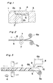
- a sealing device for a bearing which generally includes a bearing outer race 1 having a sealing groove 2 including a vertical face 2a and a horizontal support face 2b, a bearing inner race 3 and a bearing sealing plate 4 constituted by an adhesive material 6 applied to one or both faces of a sealing material 5 having a ring-hole or not, and the bearing sealing plate 4 is bonded and fixed to the horizontal support face of said sealing groove 2.
- the bearing sealing plate 4 is of a flat plate, and constituted by covering the surface of the sealing material 5 with the adhesive material 6.
- the sealing material 5 is made of, for example, metal, natural or synthetic rubber, plastics and the like, and is not limited in the raw material therefor so far as it is provided with air tightness.
- the adhesive material layer 6 a material which may be bonded by heating, pressurization or known methods can be used, and although the material itself is not limited, an elastic material with adhering nature including an adhesive material of thermo-plastic property of hot-melt group is preferable.
- Fig. 2 shows one embodiment of the adhering method of the adhesive material layer 6 onto the sealing material 5 for the bearing sealing plate 4, in which the sealing material 5 drawn out of its roll 5a, and that adhesive material 6 drawn out of its roll 6a respectively are passed between a set of rollers 7 for adhesion to each other under pressure.
- the bearing sealing plates 4 of a desired size are punched out by metal dies (not shown in Fig. 2).
- Fig. 3 shows another method of producing the bearing sealing plate 4.
- the adhesive material 6b contained in a vessel 8 is melted through heating by heating means 10, e.g., an electric heater or the like, and the molten adhesive material 6b is discharged through a nozzle 9 of the vessel 8 onto the upper surface of the sealing material 5 drawn out from a roll 5b, thereby to cause the adhesive material 6b to adhere onto the surface of the sealing material 5.
- the belt-like sheet thus prepared is blanked by metal dies 11 to prepare the bearing sealing plate 4.
- the sealing plate 4 For mounting such bearing sealing plate 4 as described so far into the sealing groove 2 in the bearing outer race 1, the sealing plate 4 is fitted into the sealing groove 2, with the adhesive material layer 6 directed downwards, and by contacting the adhesive material layer 6 with the support face 2b of the sealing groove 2, the sealing plate 4 is heated from above so as to melt part or all of the adhesive material layer 6, thereby to cause the sealing plate 4 to adhesive to said support face 2b for subsequent cooling and fixing. (Fig. 1).
- the heating of the bearing sealing plate 4 may be effected before contact with the support face 2b of the sealing groove 2, and that the heating means for the heating of the sealing plate 4 is not limited to any specific means.
- the manufacturing method of the bearing sealing plate 4 is not limited to the above, but may, for example, be so modified as to apply the molten adhesive material onto the surface of the sealing material 5 by a sprayer or by a brush.
- the adhesive material layer on the sealing plate 4 may be so arranged to cause the adhering material to adhere thereto by painting, spraying or other methods after punching the sealing material 5 in a desired shape.
- the sealing groove 2 is provided on the inner race 3 instead of being formed on the outer race 1, and the adhesive material layer 6 of the bearing sealing plate 4 is brought into contact with the support face of the sealing groove of the inner race 3 for adhesion by heating.
- a lip may be provided on the outer peripheral edge of the sealing plate 4 so as to contact the bearing outer race 1.
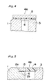
- the sealing groove 2 is not provided on the bearing outer race 1, but the sealing plate 4A prepared by causing the adhesive material layer 6 to adhere to the sealing material 5 is adapted to contact the upper surface (in Fig. 4) of the bearing outer race 1 at its side of the adhesive material layer 6, and the sealing plate 4A is heated for subsequent forced or spontaneous cooling, thereby to cause the sealing plate 4A to closely contact and to be fixed to the outer race 1.
- a clearance is provided between the upper surface (in Fig. 4) of the inner race 3 and the adhesive material layer 6 or the sealing material 5 as shown.
- the bearing sealing plate 4A in a flat disk-like shape may be modified to be a ring-like shape, and further, to be provided with a known lip in a peripheral edge of its inner hole (not shown).
- the sealing device in Fig. 4 may be further modified in such a manner that, instead of causing the sealing plate 4A to adhere to the surface of the bearing outer race 1, it may be adapted to adhere to the inner race 3. In that case, it may be so arranged to provide a lip at the outer peripheral edge portion of the bearing sealing plate, so that said lip contacts the bearing outer race.
- the configurations of the bearing sealing plate are not limited to those as shown in Fig. 1 and Fig. 4.
- the outer peripheral edge portion 13 is made of a metallic material, and its inner peripheral portion 14 is formed by an elastic material, with the adhesive material layer 6 being provided on the outer peripheral edge portion 13.
- the arrangement may be so modified that the inner peripheral portion 14 is made of a metallic material and the outer peripheral portion 13 is formed by an elastic material in the reverse order as above.
- the sealing material made of two kinds of materials may be employed as in the bearing sealing plate 4B in Fig. 5.
- the outer peripheral edge portion and the inner portion may be formed either by a metallic material or elastic material.
- the bearing sealing plate 4C as shown in Fig. 6 is of a ring-like shape, with a ring-shaped protrusion 5C being formed along an inner hole edge of the ring, and the adhesive material layer 6 is provided on the face of the sealing material 5 at its side of the protrusion 5C (excluding the under surface of the protrusion 5C) or on the outer side face of the protrusion 5C continuous on said face.
- the lip in the inner hole of the sealing plate 4C is abbreviated for brevity in the drawing.
- sealing plate 4C since the adhesive material layer 6 is not provided on the under surface of the protrusion 5C in the ring-like shape, an unused sealing plate 4C may be overlapped therewith for storing.
- sealing plate 4C it may be so modified to place the outer peripheral portion of the sealing plate 4C on the upper surface (in Fig. 6) of the bearing outer race 1 for use by adhering, without providing the sealing groove 2 on the outer race 1.
- the protrusion 5C may be provided on the outer peripheral edge of the sealing plate, instead of being provided on the ring inner hole edge.
- the bearing sealing plate 4D as shown in Fig. 7 is of a ring-shape, and includes an outer peripheral portion 17 in a horizontal plane, an intermediate portion 18 inclined upwardly from the portion 17, and an inner hole edge portion 19 extending horizontally laterally from said intermediate portion 17 as shown, with an adhesive material layer 6 is provided on the under surface of said outer peripheral portion 17.
- a lip may further be provided along the inner hole edge.
- the bearing sealing plate 4D is fitted into a sealing groove 20 of a conventional bearing outer race 1 for use, after contacting the adhesive material layer 6 on the under surface of the outer peripheral portion 17 of the fitted sealing plate 4D, with the support face 20a of the sealing groove 20, the sealing plate 4D is heated, and thereafter, cooled so as to be bonded and fixed to said support face 20a.
- the bearing sealing plate 4D is bonded and fixed onto the upper surface (in Fig. 7) of the bearing outer race 1 not provided with the sealing groove 20.
- thickness (i.e., height in Fig. 7) of the bearing outer race 1 is made thinner than that of the inner race 3.
- the sealing plates made of metallic materials there are available the sealing plates of curl type, root type and washer type, each of which, however, has a problem in the sealing performance.
- the sealing performance may be improved by providing the adhesive material layer 6 on the surfaces contacting the concave portion of the sealing groove of the outer race or the support face of the sealing groove, and by bonding the metallic sealing plate with the bearing outer race with the adhesive material.
- the layers or films may be formed through employment of the known adhesive material or elastic material with adhesive nature as the adhesive material of the adhesive material layer 6, and the adhesive material is not limited to the thermo-plastic adhesive material.
- any of the foregoing embodiments it may be so arranged to cause the adhesive material to adhere to the surface of the bearing outer race or inner race contacting the sealing plate instead of subjecting the adhesive material to adhere to the sealing plate.
- the adhesion between the bearing sealing plate and the bearing outer race or inner race is not limited to that by the heating method, but heating, pressurization or known methods therefor may be employed according to the nature of the adhesive material.
- Figs. 9(A) and 9(B) show another method for mounting the bearing sealing plate.
- a sealing groove 24 including a vertical face 24a and a horizontal support face 24b is provided on the bearing outer race 1, and a concave portion 25 is continuously or intermittently formed on the entire surface of the vertical face 24a.
- the bearing sealing plate 4F is provided with a rather thick adhesive material layer 6F of a thermo-plastic resin formed on at least one surface of a sealing material 5F.
- This adhesive material layer 6F is adapted to be slightly thicker over the entire surface or at least on the outer peripheral portion thereof.
- the sealing plate 4F is inserted into the sealing groove 24, with the adhesive material layer 6F directed downward, and thus, the adhesive material layer 6F is caused to adhere to the support face 24b of the sealing groove 24. Then, the sealing plate 4F is heated and pressurized, and part of the molten adhesive material is depressed so as to flow into the concave portion 25 provided in the vertical face 24a and to be filled therein. Subsequently, the bearing sealing plate 6F is subjected to natural or forcible cooling or drying, thereby to solidify the adhesive material.
- the protruding portion 6Fa of the adhesive material layer 6F hardened in the concave portion 25 prevents the sealing plate 4F from coming off the sealing groove 24, thus positively maintaining the mounting strength to the bearing outer race.
- the arrangement may, for example, be so modified that the sealing groove 24 is provided on the inner race 3 instead of the outer race 1, with a concave portion equivalent to the concave portion 25 being provided in said sealing groove.
- the bearing sealing plate is provided with a rather thick adhesive material layer of a thermo-plastic resin formed on at least one surface of the sealing material. This adhesive material layer is adapted to be slightly thicker over the entire surface or at least on the inner peripheral portion.
- the mounting method of the bearing sealing plate and formation of the protrusion of the adhesive layer and its effect, etc. are similar to those in the above arrangement.
- the sealing groove of the bearing outer race or inner race may be simply constituted by the vertical face and horizontal face, and the wall face of the sealing groove is not required to be curved as in the conventional constructions. Moreover, since the bearing outer race or inner race to formed with the sealing groove itself may be employed, higher strength can be achieved as compared with conventional outer race or inner race.
- the concave portion in the case where the concave portion is provided in the vertical face of the sealing groove, and the adhesive material of the adhesive material layer is continuously directed into said concave portion to be filled therein for solidification, the hardened adhesive material in said concave portion acts as a retainer or anchor for the bearing sealing plate, thereby providing higher mounting strength of the sealing plate.
Landscapes
- Engineering & Computer Science (AREA)
- General Engineering & Computer Science (AREA)
- Mechanical Engineering (AREA)
- Sealing Of Bearings (AREA)
- Rolling Contact Bearings (AREA)
Applications Claiming Priority (4)
| Application Number | Priority Date | Filing Date | Title |
|---|---|---|---|
| JP32487892 | 1992-11-10 | ||
| JP324878/92 | 1992-11-10 | ||
| JP294560/93 | 1993-10-29 | ||
| JP5294560A JPH06200949A (ja) | 1992-11-10 | 1993-10-29 | 軸受用密封板の装着方法および軸受用密封装置 |
Publications (3)
| Publication Number | Publication Date |
|---|---|
| EP0597421A2 true EP0597421A2 (de) | 1994-05-18 |
| EP0597421A3 EP0597421A3 (de) | 1994-10-12 |
| EP0597421B1 EP0597421B1 (de) | 1999-02-10 |
Family
ID=26559886
Family Applications (1)
| Application Number | Title | Priority Date | Filing Date |
|---|---|---|---|
| EP93118080A Expired - Lifetime EP0597421B1 (de) | 1992-11-10 | 1993-11-08 | Lagerdichtungsvorrichtung und Verfahren zum Montieren einer Dichtungsscheibe |
Country Status (5)
| Country | Link |
|---|---|
| US (1) | US5882121A (de) |
| EP (1) | EP0597421B1 (de) |
| JP (1) | JPH06200949A (de) |
| CN (1) | CN1054908C (de) |
| DE (1) | DE69323472T2 (de) |
Cited By (3)
| Publication number | Priority date | Publication date | Assignee | Title |
|---|---|---|---|---|
| GB2305697A (en) * | 1995-09-29 | 1997-04-16 | Michael Mcallister | In-line skate wheel cover |
| DE19900469B4 (de) * | 1998-01-08 | 2012-11-29 | Nsk Ltd. | Wälzlager |
| EP3462049A1 (de) * | 2017-09-29 | 2019-04-03 | Globeride, Inc. | Magnetische fluiddichtungsvorrichtung und magnetisches fluiddichtes lager |
Families Citing this family (9)
| Publication number | Priority date | Publication date | Assignee | Title |
|---|---|---|---|---|
| US7031106B2 (en) * | 2000-02-01 | 2006-04-18 | Nsk Ltd. | Sealing member, rolling bearing, thin motor, and bearing device |
| JP2002267028A (ja) * | 2001-03-07 | 2002-09-18 | Shimano Inc | 部品組立体 |
| US8061903B2 (en) * | 2010-01-28 | 2011-11-22 | Rexnord Industries, Llc | Bearing assembly with extended maintenance interval |
| US8740464B2 (en) | 2011-11-02 | 2014-06-03 | Rexnord Industries, Llc | Bearing assembly having a floating seal |
| MX2014010770A (es) | 2012-03-08 | 2014-10-14 | Weatherford Lamb | Transductor optico con via de paso integrada. |
| WO2016145623A1 (en) * | 2015-03-18 | 2016-09-22 | The Timken Company | Fixture for installing a seal wear ring |
| DE102017107005B3 (de) | 2017-03-31 | 2018-09-13 | Schaeffler Technologies AG & Co. KG | Abgedichtetes Wälzlager |
| JP7262182B2 (ja) * | 2018-05-31 | 2023-04-21 | ミネベアミツミ株式会社 | 軸受装置 |
| US12151509B2 (en) | 2020-10-12 | 2024-11-26 | Federal-Mogul Motorparts Llc | Wheel hub assembly and method of testing |
Family Cites Families (5)
| Publication number | Priority date | Publication date | Assignee | Title |
|---|---|---|---|---|
| GB599095A (en) * | 1945-09-13 | 1948-03-04 | Fischer Bearings Company Ltd | Improvements relating to sealed bearings |
| US2140672A (en) * | 1937-04-17 | 1938-12-20 | Glenn L Martin Co | Method of producing a seal |
| FR1477701A (fr) * | 1966-03-10 | 1967-04-21 | Sfim | Perfectionnements aux roulements, notamment aux roulements à bague extérieure tournante |
| JPH022526U (de) * | 1988-06-16 | 1990-01-09 | ||
| DE4135035A1 (de) * | 1991-10-23 | 1993-04-29 | Hoechst Ag | Seitliche kugellagerabkapselung und kugellager enthaltend dieselbe |
-
1993
- 1993-10-29 JP JP5294560A patent/JPH06200949A/ja active Pending
- 1993-11-08 DE DE69323472T patent/DE69323472T2/de not_active Expired - Lifetime
- 1993-11-08 EP EP93118080A patent/EP0597421B1/de not_active Expired - Lifetime
- 1993-11-10 CN CN93112940A patent/CN1054908C/zh not_active Expired - Fee Related
-
1997
- 1997-04-10 US US08/834,862 patent/US5882121A/en not_active Expired - Fee Related
Cited By (4)
| Publication number | Priority date | Publication date | Assignee | Title |
|---|---|---|---|---|
| GB2305697A (en) * | 1995-09-29 | 1997-04-16 | Michael Mcallister | In-line skate wheel cover |
| DE19900469B4 (de) * | 1998-01-08 | 2012-11-29 | Nsk Ltd. | Wälzlager |
| EP3462049A1 (de) * | 2017-09-29 | 2019-04-03 | Globeride, Inc. | Magnetische fluiddichtungsvorrichtung und magnetisches fluiddichtes lager |
| US10451115B2 (en) | 2017-09-29 | 2019-10-22 | Globeride, Inc. | Magnetic fluid sealing device and magnetic fluid sealed bearing |
Also Published As
| Publication number | Publication date |
|---|---|
| DE69323472T2 (de) | 1999-08-05 |
| CN1054908C (zh) | 2000-07-26 |
| DE69323472D1 (de) | 1999-03-25 |
| EP0597421B1 (de) | 1999-02-10 |
| CN1095800A (zh) | 1994-11-30 |
| US5882121A (en) | 1999-03-16 |
| JPH06200949A (ja) | 1994-07-19 |
| EP0597421A3 (de) | 1994-10-12 |
Similar Documents
| Publication | Publication Date | Title |
|---|---|---|
| EP0597421A2 (de) | Lagerdichtungsvorrichtung und Verfahren zum Montieren einer Dichtungsscheibe | |
| US4459092A (en) | Apparatus for integrally molding an ornament plate on a plastic body | |
| US6066184A (en) | Voltaic cell | |
| US4595117A (en) | Sealing lip for lid on thermoformed container | |
| US4131211A (en) | Receptacle made of thermoplastic material | |
| JPH0415091B2 (de) | ||
| JPH10242733A (ja) | 車両用アンテナ内蔵外装部品 | |
| US4078287A (en) | Method of forming sealing members | |
| AU576740B2 (en) | An improved mounting cup and method of making same | |
| US3454692A (en) | Method of forming vehicular rearview mirrors | |
| US4659405A (en) | Method and apparatus for making a sealing lip for lid on thermoformed container | |
| EP0636820B1 (de) | Lagerdichtungsplatte und ihr Herstellungsverfahren | |
| US4370689A (en) | Flexible magnetic recording medium with improved reinforcement means | |
| US3557420A (en) | Method for making an antifriction bearing seal | |
| JPH0629165A (ja) | 電解コンデンサ用ゴム封口体の製造方法 | |
| JPH10278931A (ja) | 二重容器 | |
| JPH11154503A (ja) | 鉛蓄電池用端子 | |
| JP2956491B2 (ja) | 金属と合成樹脂の複合蓋とその製造装置 | |
| JPH02258320A (ja) | 芯部材を有する樹脂成形品の製造方法 | |
| JPH08197648A (ja) | パッド付きプラスチック成形品およびその製造方法 | |
| JPS5845960Y2 (ja) | モ−ルデイング | |
| WO1997003807A3 (en) | Process of making b-pillar covers and covers produced thereby | |
| JPS63307950A (ja) | 印刷用パッド | |
| JPH0564571U (ja) | 密封装置 | |
| JP3602982B2 (ja) | ベアリングシールとその製造方法 |
Legal Events
| Date | Code | Title | Description |
|---|---|---|---|
| PUAI | Public reference made under article 153(3) epc to a published international application that has entered the european phase |
Free format text: ORIGINAL CODE: 0009012 |
|
| 17P | Request for examination filed |
Effective date: 19931206 |
|
| AK | Designated contracting states |
Kind code of ref document: A2 Designated state(s): DE FR GB |
|
| PUAL | Search report despatched |
Free format text: ORIGINAL CODE: 0009013 |
|
| AK | Designated contracting states |
Kind code of ref document: A3 Designated state(s): DE FR GB |
|
| 17Q | First examination report despatched |
Effective date: 19951013 |
|
| GRAG | Despatch of communication of intention to grant |
Free format text: ORIGINAL CODE: EPIDOS AGRA |
|
| GRAG | Despatch of communication of intention to grant |
Free format text: ORIGINAL CODE: EPIDOS AGRA |
|
| GRAH | Despatch of communication of intention to grant a patent |
Free format text: ORIGINAL CODE: EPIDOS IGRA |
|
| GRAH | Despatch of communication of intention to grant a patent |
Free format text: ORIGINAL CODE: EPIDOS IGRA |
|
| GRAA | (expected) grant |
Free format text: ORIGINAL CODE: 0009210 |
|
| AK | Designated contracting states |
Kind code of ref document: B1 Designated state(s): DE FR GB |
|
| ET | Fr: translation filed | ||
| REF | Corresponds to: |
Ref document number: 69323472 Country of ref document: DE Date of ref document: 19990325 |
|
| PLBE | No opposition filed within time limit |
Free format text: ORIGINAL CODE: 0009261 |
|
| STAA | Information on the status of an ep patent application or granted ep patent |
Free format text: STATUS: NO OPPOSITION FILED WITHIN TIME LIMIT |
|
| 26N | No opposition filed | ||
| REG | Reference to a national code |
Ref country code: GB Ref legal event code: IF02 |
|
| PGFP | Annual fee paid to national office [announced via postgrant information from national office to epo] |
Ref country code: GB Payment date: 20091124 Year of fee payment: 17 Ref country code: FR Payment date: 20091027 Year of fee payment: 17 |
|
| PGFP | Annual fee paid to national office [announced via postgrant information from national office to epo] |
Ref country code: DE Payment date: 20091229 Year of fee payment: 17 |
|
| GBPC | Gb: european patent ceased through non-payment of renewal fee |
Effective date: 20101108 |
|
| REG | Reference to a national code |
Ref country code: DE Ref legal event code: R119 Ref document number: 69323472 Country of ref document: DE Effective date: 20110601 Ref country code: DE Ref legal event code: R119 Ref document number: 69323472 Country of ref document: DE Effective date: 20110531 |
|
| REG | Reference to a national code |
Ref country code: FR Ref legal event code: ST Effective date: 20110801 |
|
| PG25 | Lapsed in a contracting state [announced via postgrant information from national office to epo] |
Ref country code: DE Free format text: LAPSE BECAUSE OF NON-PAYMENT OF DUE FEES Effective date: 20110531 |
|
| PG25 | Lapsed in a contracting state [announced via postgrant information from national office to epo] |
Ref country code: FR Free format text: LAPSE BECAUSE OF NON-PAYMENT OF DUE FEES Effective date: 20101130 |
|
| PG25 | Lapsed in a contracting state [announced via postgrant information from national office to epo] |
Ref country code: GB Free format text: LAPSE BECAUSE OF NON-PAYMENT OF DUE FEES Effective date: 20101108 |