EP0597437A1 - Dispositif d'ouverture d'enveloppes - Google Patents
Dispositif d'ouverture d'enveloppes Download PDFInfo
- Publication number
- EP0597437A1 EP0597437A1 EP93118111A EP93118111A EP0597437A1 EP 0597437 A1 EP0597437 A1 EP 0597437A1 EP 93118111 A EP93118111 A EP 93118111A EP 93118111 A EP93118111 A EP 93118111A EP 0597437 A1 EP0597437 A1 EP 0597437A1
- Authority
- EP
- European Patent Office
- Prior art keywords
- envelope
- air stream
- airflow
- shifting plate
- opening device
- Prior art date
- Legal status (The legal status is an assumption and is not a legal conclusion. Google has not performed a legal analysis and makes no representation as to the accuracy of the status listed.)
- Ceased
Links
Images


Classifications
-
- B—PERFORMING OPERATIONS; TRANSPORTING
- B43—WRITING OR DRAWING IMPLEMENTS; BUREAU ACCESSORIES
- B43M—BUREAU ACCESSORIES NOT OTHERWISE PROVIDED FOR
- B43M3/00—Devices for inserting documents into envelopes
- B43M3/04—Devices for inserting documents into envelopes automatic
- B43M3/045—Devices for inserting documents into envelopes automatic for envelopes with only one flap
Definitions
- This invention relates to an envelope opening device, and, more particularly, to an envelope mouth opener for ready access of enclosure such as a direct mail or the like to the envelope before the envelope is sealed by an automatic envelope sealing apparatus in which such the envelope opening device is to be used.
- a system or a mechanism, as shown in Fig. 4, which handles a great number of envelopes for enclosing the enclosure in each of the envelopes and then sealing the envelopes has been well known as an automatic envelope sealing apparatus.
- an envelope stacker 1 is adapted to accommodate a plurality of envelopes E in a stack, each of which is empty of the enclosure.
- the envelopes E which are successively taken out of the stacker 1 are also successively fed downwardly by a conveyor mechanism composed of a plurality of rollers R1 - R6 and then clamped one by one by a gripper G moving on a predetermined annular path.
- the gripper G with the envelope E clamped thereby is moved from a first position Po and through positions P1, P2 and P3 where each of enclosures as a direct mail, a printed matter, papers and the like are enclosed therein.
- FIG. 4 there is shown the manner in which the envelope E is successively subjected to various handlings in a position P1 where a flap E1 of the envelope E is opened, a position P2 where the enclosure L is inserted in the envelope E, and in a position P3 where the envelope E with the enclosure L therein is ready for conveyance to an envelope sealing mechanism (not shown) which is designed to apply moistening treatment to the flap E1, bend the flap, and seal the envelope.
- an envelope sealing mechanism (not shown) which is designed to apply moistening treatment to the flap E1, bend the flap, and seal the envelope.
- An enclosure enclosing device of this class as aforementioned is required to open the mouth Ea of the envelope E to smoothly insert the enclosure L.
- a guide plate B has been customarily entered into the mouth Ea of the envelope to open the envelope E, as shown in Fig. 5.
- This approach conventionally necessitates an envelope opener as shown in Fig. 6 so that the mouth Ea of the envelope is opened even before inserting the guide plate B to prevent the guide plate B from interfering with the mouth Ea.
- This type of the envelope opening device is designed so that air supplied from an air supply source such as a compressor 1 or the like is held at a predetermined pressure and then fed by an electromagnet valve 3 to a nozzle 4 from which air is jetted toward the mouth Ea.
- the electromagnet valve 3 is opened to have the nozzle 4 jetted and fed air to the interior of the envelope so that the mouth Ea is opened under air pressure.
- the guide plate B is prevent from abutting against the mouth Ea and entered into the envelope E without any difficulty.
- the electromagnet valve is closed to prevent air from being jetted. This will move the enclosure L smoothly without being subjected to the airflow.
- a compressor 5 is utilized as a source of air supply, thus, it is required to provide an electromagnetic valve 3 for controlling the supply and interception of the air through the nozzle 4 and a regulator 2 for obtaining a suitable air pressure.
- Such a valve 3 and the regulator 2 are expensive and, thus, a prior art device utilizing such parts is expensive.
- a motor driven fan is disposed near to the position P2 and, by controlling the start and stop of the motor driving the fan the supply and intercept of the air is performed.
- the device enables a substantial reduction in cost by utilizing an electric motor and a fan which are inexpensive.
- An object of the invention is to provide a novel envelope opening device which enables rapid shifting of the supply and stop of air into the opening of an envelope, and to thereby reduce costs.
- an envelope opening device for opening an opening portion of an envelope, by supplying air into the opening portion, with the envelope being delivered sequentially to a predetermined position
- the device comprises an air stream generating means for generating the air stream by rotating a motor driven fan, an air stream shifting plate for directing the air stream to an opening portion of an envelope which is retained at a predetermined position and in a direction other than that of the opening portion, and a driving means for actuating the air stream shifting plate, with the motor driven fan being continuously driven during the operation of envelope supplying means.
- the air stream generating means is disposed on the up-stream side of an enclosure inserting position and above a surface generally perpendicularly intersecting with the enclosure inserting direction, with the air stream shifting plate being disposed between the air stream generating means and a guide plate for holding an opening portion of the envelope in open condition, and the air stream shifting plate effects shifting movement when the envelope is arrived to the enclosure inserting position and when the guide plate is inserted into the envelope.
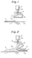
- FIG. 11 shown at numeral 11 is an envelope support pedestal supporting the envelope E which is transported to the position P2 (Fig. 4) by the gripper G.
- Shown at numeral 12 is an enclosure support table provided to oppose the rear end of the envelope support pedestal 11 for supporting an enclosure L thereon. The enclosure L is moved forward by an enclosure inserting device not shown in the drawing and into the envelope E supported on the envelope support pedestal 11.
- Shown at numeral 13 is an electric motor supported above the rear end portion of the enclosure support table 12 through a suitable mounting member not shown in the drawing, and at 14 is a fan mounted on a rotatable shaft 13a of the motor 13.
- the fan 14 is driven by the motor 13 to supply the airflow generally vertically downward and to the front end portion of the enclosure support table 12.
- the motor 13 and the fan 14 constitute air stream generating means.
- Shown at numeral 15 is an air stream shifting plate provided between the fan 14 and the enclosure support table 12, and the shifting plate 15 is secured to a shaft 16 which is rotatably mounted on a support member not shown in the drawing.
- the shaft 16 is rotatable through a predetermined angle by means of a solenoid (not shown) which acts as driving means.
- the air stream shifting plate 15 is rotatable between a shut-off position shown in Fig. 1 and a supply position shown in Fig. 2 by the rotary movement of the shaft 16.
- the motor 13 of the envelope opening device is also actuated and the fan 14 starts to supply air stream.
- the fan 14 continues the rotation during the actuation of the machine.
- the air stream shifting plate 15 is normally maintained at the position shown in Fig. 1 with the solenoid not shown in the drawing is maintained inactuated condition, and the air stream supplied from the fan 14 is directed in generally horizontal direction.
- the air stream of the fan 14 is guided to the opening portion Ea of the envelope E and the opening portion Ea is opened by the air pressure as shown in Fig. 2. Under this condition, the guide plate B is inserted into the opening portion Ea, thus, the operation is smooth.
- the supply and intercept of the air stream to the envelope E can be performed instantly by the shifting operation of the air stream shifting plate 15, thus, it is possible to instantly start the inserting operation of the enclosure L into the envelope E when the guide plate B has been inserted into the envelope E. Therefore, as compared with the prior art device, in which it is required to suspend the inserting operation of the enclosure L into the envelope E until the rotation of the fan is terminated, it is possible to reduce substantially the cycle time of the mail inserting and sealing machine.
- the air stream shifting plate 15 moves between a position directly opposing the fan 14 and a position intersecting at an acute angle with the direction of the air stream, however, the location and arrangement of the fan 14 and the air stream shifting plate 15 can be determined as desired.
- the envelope opening device is constituted of a fan driven by an electric motor and an air stream shifting plate for shifting the direction of the air stream supplied by the fan, thus, it is possible to substantially reduce the cost as compared with the prior art device utilizing expensive air parts such as an electromagnetic valve and a regulator and the like.
- the air stream shifting plate according to the present invention enables instant switch of the supply and interception of the air stream to the opening portion of the envelope, thus, as compared with the prior art device utilizing a fan, it is possible to substantially reduce the working time and to substantially increase working efficiency.
Landscapes
- Supplying Of Containers To The Packaging Station (AREA)
Applications Claiming Priority (2)
| Application Number | Priority Date | Filing Date | Title |
|---|---|---|---|
| JP77289/92U | 1992-11-10 | ||
| JP7728992U JPH0642618U (ja) | 1992-11-10 | 1992-11-10 | 封筒開口装置 |
Publications (1)
| Publication Number | Publication Date |
|---|---|
| EP0597437A1 true EP0597437A1 (fr) | 1994-05-18 |
Family
ID=13629722
Family Applications (1)
| Application Number | Title | Priority Date | Filing Date |
|---|---|---|---|
| EP93118111A Ceased EP0597437A1 (fr) | 1992-11-10 | 1993-11-09 | Dispositif d'ouverture d'enveloppes |
Country Status (2)
| Country | Link |
|---|---|
| EP (1) | EP0597437A1 (fr) |
| JP (1) | JPH0642618U (fr) |
Cited By (2)
| Publication number | Priority date | Publication date | Assignee | Title |
|---|---|---|---|---|
| GB2369340A (en) * | 2000-11-28 | 2002-05-29 | Pitney Bowes Technologies Gmbh | Envelope filling apparatus having an auxiliary envelope filling arrangement |
| US7905076B2 (en) * | 2008-11-20 | 2011-03-15 | Pitney Bowes Inc. | Apparatus and method for conveying envelopes in a mailpiece insertion system |
Families Citing this family (1)
| Publication number | Priority date | Publication date | Assignee | Title |
|---|---|---|---|---|
| FR2859945B1 (fr) * | 2003-09-18 | 2006-09-22 | Kern Ag | Dispositif automatique de mise sous plis de pieces de faible encombrement, notamment de documents |
Citations (4)
| Publication number | Priority date | Publication date | Assignee | Title |
|---|---|---|---|---|
| US3410053A (en) * | 1965-06-14 | 1968-11-12 | Baeuerle Gmbh Mathias | Machine for the automatic insertion of enclosures, such as letters, printed matter and the like |
| DE1461694A1 (de) * | 1963-10-28 | 1969-03-20 | Standard Elek K Lorenz Ag | Einrichtung zum Vorbereiten von Briefumschlaegen zur Aufnahme von Einlagen |
| JPH039897A (ja) * | 1989-06-06 | 1991-01-17 | Daizou Eng:Kk | 自動封入機 |
| US5097654A (en) * | 1991-02-19 | 1992-03-24 | Antonio Latsounas | Envelope filler and sealer |
-
1992
- 1992-11-10 JP JP7728992U patent/JPH0642618U/ja active Pending
-
1993
- 1993-11-09 EP EP93118111A patent/EP0597437A1/fr not_active Ceased
Patent Citations (4)
| Publication number | Priority date | Publication date | Assignee | Title |
|---|---|---|---|---|
| DE1461694A1 (de) * | 1963-10-28 | 1969-03-20 | Standard Elek K Lorenz Ag | Einrichtung zum Vorbereiten von Briefumschlaegen zur Aufnahme von Einlagen |
| US3410053A (en) * | 1965-06-14 | 1968-11-12 | Baeuerle Gmbh Mathias | Machine for the automatic insertion of enclosures, such as letters, printed matter and the like |
| JPH039897A (ja) * | 1989-06-06 | 1991-01-17 | Daizou Eng:Kk | 自動封入機 |
| US5097654A (en) * | 1991-02-19 | 1992-03-24 | Antonio Latsounas | Envelope filler and sealer |
Non-Patent Citations (1)
| Title |
|---|
| PATENT ABSTRACTS OF JAPAN vol. 015, no. 120 (M - 1096) 25 March 1991 (1991-03-25) * |
Cited By (4)
| Publication number | Priority date | Publication date | Assignee | Title |
|---|---|---|---|---|
| GB2369340A (en) * | 2000-11-28 | 2002-05-29 | Pitney Bowes Technologies Gmbh | Envelope filling apparatus having an auxiliary envelope filling arrangement |
| GB2369340B (en) * | 2000-11-28 | 2004-05-05 | Pitney Bowes Technologies Gmbh | Envelope-filling apparatus having an auxiliary envelope-filling arrangement |
| US7905076B2 (en) * | 2008-11-20 | 2011-03-15 | Pitney Bowes Inc. | Apparatus and method for conveying envelopes in a mailpiece insertion system |
| EP2189297A3 (fr) * | 2008-11-20 | 2012-06-13 | Pitney Bowes Inc. | Transport d'enveloppes |
Also Published As
| Publication number | Publication date |
|---|---|
| JPH0642618U (ja) | 1994-06-07 |
Similar Documents
| Publication | Publication Date | Title |
|---|---|---|
| US5722221A (en) | Envelope opening apparatus | |
| US6164046A (en) | High speed machine for inserting sheets into envelopes | |
| CA1300575C (fr) | Dispositif servant a ouvrir les enveloppes | |
| US3936993A (en) | Envelope filling machine | |
| JP3522386B2 (ja) | 給紙装置の吸引ベルト式給紙台における負圧を紙葉供給の間に変化した運転条件に適合させる装置 | |
| CA1232173A (fr) | Dispositif pour dresser les rabats d'enveloppes | |
| EP0597437A1 (fr) | Dispositif d'ouverture d'enveloppes | |
| US3078089A (en) | Document stacking device | |
| US4736941A (en) | Method and apparatus for braking and delivering printed sheets or sheet packages | |
| US7188460B2 (en) | High speed vacuum system for inserters | |
| EP0755887A3 (fr) | Procédé et dispositif pour freiner pneumatiquement des feuilles dans le dispositif de décharge d'une machine rotative d'impression de feuilles | |
| US5642598A (en) | Collation feeding mechanism for envelope inserting machine | |
| GB1154121A (en) | Machine for Automatically Inserting Letters, Printed Matter, or the like into Envelopes. | |
| EP0739844B1 (fr) | Combinaison dispositif d'aiguillage, trieuse collationneuse et boíte de réception pour des dispositifs d'impression | |
| US4888938A (en) | Envelope throat opening blade | |
| US3927876A (en) | Device for singulating documents | |
| US6453651B1 (en) | High speed machine for inserting sheets into envelopes | |
| US7181895B1 (en) | Jam tolerant mail inserter | |
| EP1315656B1 (fr) | Machine d'insertion a grande vitesse de feuilles dans des enveloppes | |
| JPH054620A (ja) | 袋体の1枚宛取出装置 | |
| US3420515A (en) | Machine for automatically loading and unloading fabric creasers | |
| JPH07187481A (ja) | 印刷後紙葉のための丁合機 | |
| EP0375799A1 (fr) | Dispositif de délivrance pour une presse à imprimer à feuilles | |
| WO2000017052A1 (fr) | Appareil et dispositif d'insertion a mouvement continu commandee par des servomoteurs | |
| US4239485A (en) | Taped products processor |
Legal Events
| Date | Code | Title | Description |
|---|---|---|---|
| PUAI | Public reference made under article 153(3) epc to a published international application that has entered the european phase |
Free format text: ORIGINAL CODE: 0009012 |
|
| AK | Designated contracting states |
Kind code of ref document: A1 Designated state(s): CH DE FR GB LI |
|
| 17P | Request for examination filed |
Effective date: 19940519 |
|
| 17Q | First examination report despatched |
Effective date: 19941011 |
|
| STAA | Information on the status of an ep patent application or granted ep patent |
Free format text: STATUS: THE APPLICATION HAS BEEN REFUSED |
|
| 18R | Application refused |
Effective date: 19960413 |