EP0597440B1 - Schutzverfahren für umlaufende Strömungsablösung für Verdichter - Google Patents
Schutzverfahren für umlaufende Strömungsablösung für Verdichter Download PDFInfo
- Publication number
- EP0597440B1 EP0597440B1 EP93118140A EP93118140A EP0597440B1 EP 0597440 B1 EP0597440 B1 EP 0597440B1 EP 93118140 A EP93118140 A EP 93118140A EP 93118140 A EP93118140 A EP 93118140A EP 0597440 B1 EP0597440 B1 EP 0597440B1
- Authority
- EP
- European Patent Office
- Prior art keywords
- flow
- sensors
- vanes
- compressor
- casing
- Prior art date
- Legal status (The legal status is an assumption and is not a legal conclusion. Google has not performed a legal analysis and makes no representation as to the accuracy of the status listed.)
- Expired - Lifetime
Links
- 230000002265 prevention Effects 0.000 title description 11
- 239000012530 fluid Substances 0.000 claims description 19
- 238000011144 upstream manufacturing Methods 0.000 claims description 15
- 230000000704 physical effect Effects 0.000 claims 1
- 230000001105 regulatory effect Effects 0.000 claims 1
- 230000002093 peripheral effect Effects 0.000 description 16
- 239000013598 vector Substances 0.000 description 5
- 238000009826 distribution Methods 0.000 description 3
- 230000000694 effects Effects 0.000 description 3
- 238000000926 separation method Methods 0.000 description 2
- 238000013459 approach Methods 0.000 description 1
- 230000006866 deterioration Effects 0.000 description 1
- 230000002542 deteriorative effect Effects 0.000 description 1
- 238000010586 diagram Methods 0.000 description 1
- 230000006870 function Effects 0.000 description 1
- 230000000977 initiatory effect Effects 0.000 description 1
Images


Classifications
-
- F—MECHANICAL ENGINEERING; LIGHTING; HEATING; WEAPONS; BLASTING
- F04—POSITIVE - DISPLACEMENT MACHINES FOR LIQUIDS; PUMPS FOR LIQUIDS OR ELASTIC FLUIDS
- F04D—NON-POSITIVE-DISPLACEMENT PUMPS
- F04D27/00—Control, e.g. regulation, of pumps, pumping installations or pumping systems specially adapted for elastic fluids
- F04D27/02—Surge control
- F04D27/0246—Surge control by varying geometry within the pumps, e.g. by adjusting vanes
Definitions
- the invention relates to an axial compressor, comprising the featurs of the first part of claim 1.
- Such an axial compressor is disclosed in the GB-A-2 191 606.
- a partial stalling region called as a cell
- the rotating stall phenomena is caused by the circumferential inlet distortion of the fluid flowing into the blade rows. Therefore, the rotating stall phenomena has been understood to include circumferential distortion of the fluid before flowing into the blade rows.
- a system preventing such a rotating stall is described in a paper ASME paper 91-GT-88 issued in July 1991.
- the system described in this paper has a plurality of hot wire anemometers arranged in the peripheral direction of a casing to detect a rotating stall (circumferential inlet distortion of flow), and the setting angles of a plurality of inlet guide vanes are controlled with mutual phase differences based on the detected signals so as to eliminate the rotating stall to the peripheral direction.
- the setting angles of the inlet guide canes are changed with DC motors operated by the command from a control circuit.
- the axial compressor disclosed in the GB-A-2 191 606 is provided with a control system for controlling the rotor blade flutter, the rotating stall, the surge, force vibrations and acoustic resonances.
- a sensor array is provided in the compressor and an electronic controller having a selector/filter selects those signal components from the output of the sensor array.
- an actuator array adjust the angles of the inlet guide vanes.
- An object of the invention is to solve problems existing in the prior technology described above and to provide a rotating stall prevention system for compressor which is high in preventing efficiency against the rotating stall and low in affecting deterioration in the fluid performance of compressor.
- Rotating stall is a phenomena where a partial stalling region, called as a cell, is caused by flow separation from the blades and rotationally propagates at a speed of approximately a half rotating speed of the compressor.
- the flow velocity in the peripheral direction in a partially stalling region is larger than that in a non-stalling region, or the axial flow velocity in a partially stalling region is smaller than that in a non-stalling region, and the blade angle of attack against flow in a partially stalling region is larger than that in a non-stalling region.
- the pressure in a partially stalling region is higher than that in a non-stalling region. That is, when a rotating stall takes place, the flow velocity and the pressure become uneven distributions over the peripheral direction.
- the most dominant factor causing initiation of the rotating stall is the inlet distortion (uneven distributions) in flow velocity, pressure and temperature at an inlet of the compressor due to the asymmetry in its shape and so on.
- the distortion gradually increases from the inlet of the compressor to the inlet of the blade rows to cause the rotating stall inside the blade rows.
- This rotating stall can be predicted or detected based on the signals from flow sensors.
- the detected signals are input into control means.
- the control means carries out calculation to obtain the angles of the baffle vanes or the jet flow rates which make the flow in the passage of the compressor uniform in order to prevent the occurrence of rotating stall and controls the actuators or the control valves.
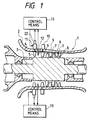
- FIG.1 shows a compressor having an embodiment of a system according to the present invention.
- a compressor 1 has a compressor flow passage 4 formed between a casing 2 and a rotor 3 installed therein.
- the casing 2 there provided from the upstream side baffle vanes 5, inlet guide vanes 6, stator blades 7 and exit guide vanes 8.
- the rotor 3 has rotor blades 9 at the positions between the inlet guide vanes 6 and the stator blades 7, and between the stator blades 7 and the stator blades 7.
- the setting angles of the inlet guide vanes 6 described above are changed depending on the operating condition (rotating speed of rotor 3) of the compressor with an angle varying mechanism 10 so that the flow rate matches to the rotating speed.
- the baffle vanes 5 installed the upstream of the inlet guide vanes 6 are, as shown in FIG.2, pivotably attached peripherally onto the casing 2 with circumferentially equal intervals.
- four baffle vanes 5 are provided.
- the baffle vanes 5 are individually driven by actuators 11 such as motors to change their setting angles.
- Hot wire anemometers 12 as flow sensors for detecting the rotating stall or the circumferential distortion of flow are provided in the downstream of the baffle vanes 5 or the upstream of the inlet guide vanes 6 with circumferentially equal intervals.
- the hot wire anemometer 12 has, as shown in FIG.3 and FIG.4, two hot wires perpendicular to each other, one is a first hot wire 12a which detects the magnitude of the flow velocity in the axial direction, and the other is a second hot wire 12b which detects the magnitude of the flow velocity in the peripheral direction.
- control means 13 for varying the angles of the baffle vanes 5, illustrated in FIG.1 comprises a flow angle processor 14 which receives the signals from the first hot wire 12a and the second hot wire 12b in the hot wire anemometer 12 to obtain the flow angle of fluid velocity ⁇ , a memory for standard flow angle 15 which stores standard flow angle data, a comparator 16 which compares the standard flow angle values from the memory for standard flow angle 15 with the detected flow angle values from the flow angle processor 14 to obtain the difference between them, a phase difference circuit 17 which produces phase difference for the difference from the comparator 16 to compensate the positional delay and the fluid inertial delay due to the setting position interval between the baffle vanes 5 and the hot wire anemometers 12, a reversing circuit 18 which changes sign of the difference from the phase difference circuit 17, a memory for standard angle of baffle vanes 19 which stores the standard angle data for the baffle vanes 5, an adder 20 which adds the standard angle for baffle vanes from the memory for standard angle of baffle vanes 19 to the
- the signals for controlling the baffle vanes angles from the adder 20 are led to the actuator 11 through a subtracter 21.
- the subtracter 11 receives the angle signals as negative feedback from a position detector 22 installed in the actuator 11.
- the memory for standard flow angle 15 described above is set to store the standard flow angle value obtained in advance, however, it is also possible to store an average value of a plurality of the flow angles obtained from a plurality of the anemometers 12 as the standard angle value.
- the hot wire anemometer 12 corresponding to the peripheral angle described above detects the flow velocity in the axial direction and the flow velocity in peripheral direction.
- the flow angle processor 14 receives the detected signal from the hot wire anemometer 12 to obtain the flow angle of fluid velocity ⁇ .
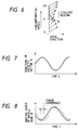
- the flow angle of fluid velocity ⁇ changes, for example, sinusoidally as the time passed as shown in FIG. 7.
- the comparator 16 the flow angle of fluid velocity ⁇ is compared with the standard flow angle values stored in the memory for standard flow angle 15 to obtain the difference between them.
- the difference is input to the phase difference circuit 17 to produce an advance phase difference to compensate the positional delay and the fluid inertial delay due to the setting position interval between the baffle vanes 5 and the hot wire anemometers 12 as shown in FIG.8.
- the difference given the phase difference is changed its sign.
- the difference reversed its signal is added to the standard angle of the baffle vanes 5 from the memory for standard angle of baffle vane 19.
- the angles for controlling the baffle vane angles are obtained.
- the angles for controlling the baffle vane angles are led to the actuator 11 through a subtracter 21.
- the actuator 11 controls, as described above, so as to lessen the angle of the baffle vane corresponding to the peripheral position of the region where the angle ⁇ is large. As the result, the direction of fluid flow vector is forced to turn to decrease the stalling region in the blade rows.
- the control for the baffle vanes 5 is performed with a certain period of cycle so as to follow the peripheral travelling of the stalling region, since the stalling region travels in such a manner.
- the control is preformed in the same manner as described above such that the angle of the baffle vane 5 approaches to the standard angle for the baffle vane to stabilize fluid flow.
- the controlled angles of the baffle vanes 5 are detected by the position detector 22 and are fed back to the subtracter 21 to control so as to keep the controlled angles agreeing with the setting values.
- the unsteady state flow field under a rotating stalling condition of compressor is actively controlled by using the baffle vanes 5, the rotating stall can certainly be prevented. And since there is no need unsteadily to change the angles of the inlet guide vanes 6 for preventing the rotating stall, the performance of the compressor is hardly affected.
- hot wire anemometers 12 are used as flow sensors in the embodiment described above, pressure sensors or temperature sensors may be used instead of the hot wire anemometers. In this case, since the pressure and the temperature in the stalling region rise, the control may be performed such that the angles of baffle vanes 5 in the peripheral position corresponding to the high pressure or high temperature region are lessened.
- flow sensors 12 and the baffle vanes 5 are provided four in number respectively in the embodiment described above, the more accurate control is capable the more number thereof provided. However, at least three sensors are sufficient.
- FIG.9 shows a compressor having another embodiment of a system according to the present invention.
- the numerals refers to same parts in FIG.1.
- hot wire anemometers 12 are installed in the upstream side of the baffle vanes 5. Such structure is also capable of obtaining the same effect as the embodiment described above.
- FIG.10 shows a compressor having a further embodiment of a system according to the present invention.
- a compressor comprises nozzles 23 to supply jet flow on a casing 2 in an upstream of inlet guide vanes 6, a compressed fluid supply 25 being connected to the nozzles 23 through valves 24, pressure signals from pressure sensors 26 provided in an upstream side of the inlet guide vanes 6 are input into control means 27, the control means 27 regulates said valves 24.
- This control means 27 may be formed by changing the flow angle in the control means 13 in FIG.1 to pressure.
- the pressure in the region corresponding to the stalling region between the upstream of the blade rows and the inlet of the blade rows is high and the pressure in the non-stalling region is low.
- the unevenness of pressure distribution in the peripheral direction can be eliminated to decrease the stalling region inside the blade rows.
- the unsteady state flow field under a rotating stalling condition of compressor is actively controlled, a high prevention effect against the rotating stall can be attained. And by providing nozzles 23 for jet flow in an upstream of the inlet guide vanes 6, the performance of the compressor is hardly affected. Furthermore, there is an advantage that the structure is simpler than that for the embodiment using the baffle vanes 5.
- an air compressor may be used as the pressurized fluid supply for the jet flow, or instead of using an air compressor the fluid from the compressor itself may be utilized.
- temperature sensors may be used instead of the pressure sensors 26.
- a plurality of nozzles 23 to supply jet flow may be provided in a downstream of the inlet guide vanes 6.
- the rotating stall can be prevented without deteriorating the performance of compressor, the efficiency of the compressor increases and the reliability of components connected downstream thereof can be improved.
Landscapes
- Engineering & Computer Science (AREA)
- Physics & Mathematics (AREA)
- Geometry (AREA)
- Mechanical Engineering (AREA)
- General Engineering & Computer Science (AREA)
- Control Of Positive-Displacement Air Blowers (AREA)
- Structures Of Non-Positive Displacement Pumps (AREA)
Claims (8)
- Axialverdichter mitan einem drehangetriebenen Läufer (3) montierten Laufschaufeln (9),in einem Gehäuse (2) montierten Statorblättern,im Gehäuse (2) stromauf von Druckschaufelreihen (9) montierten Einlaßleitschaufeln (7),Strömungssensoren (12) zum Erfassen von Strömungsverhältnissen in der Strömungsbahn zwischen dem Läufer (3) und dem Gehäuse (2),einem Winkeländerungsmechanismus (10) zum Verstellen der Anstellwinkel der Einlaßleitschaufeln (6) entsprechend den Betriebsbedingungen,
gekennzeichnet durchAblenkschaufeln (5) in der Strömungsbahn (4) stromauf der Einlaßleitschaufeln (6),die Signale der Strömungssensoren (12) aufnehmende Steuermittel (13) undStellglieder (11) zum Einstellen der Anstellwinkel der Ablenkschaufeln (5) auf der Grundlage der Ausgangssignale der Steuermittel zur Verhinderung des rotierenden Strömungsabrißphänomens. - Verdichter nach Anspruch 1, dadurch gekennzeichnet, daß die Strömungssensoren (12) zwischen den Einlaßleitschaufeln (6) und den Ablenkschaufeln (5) angeordnet sind.
- Verdichter nach Anspruch 1, dadurch gekennzeichnet, daß die Sensoren (12) stromauf der Ablenkschaufeln (5) vorgesehen sind.
- Verdichter nach einem der Ansprüche 1 bis 3, dadurch gekennzeichnet, daß die Strömungssensoren (12) der Strömungsgeschwindigkeit oder dem Fluiddruck in der Strömungsbahn (4) entsprechende Signale erzeugen.
- Verdichter nach Anspruch 1 bis 3, dadurch gekennzeichnet, daß die Strömungssensoren (12) einer axialen Strömungsgeschwindigkeit und einer Umfangsströmungsgeschwindigkeit des Fluids in der Strömungsbahn (4) entsprechende Signale erzeugen.
- Verdichter nach Anspruch 5, dadurch gekennzeichnet, daß der Strömungssensor (12) ein Hitzdrahtanemometer mit zwei zueinander senkrechten Hitzdrähten (12a, 12b) ist, von denen ein Hitzdraht (12a) zum Erfassen der Größe der axialen Strömungsgeschwindigkeit und der andere Hitzdraht (12b) zum Erfassen der Größe der Umfangsströmungsgeschwindigkeit dient.
- Verdichter nach einem der Ansprüche 1 bis 6, dadurch gekennzeichnet, daß vier Ablenkschaufeln (5) in gleicher Winkelversetzung vorgesehen sind, die individuell von den Stellgliedern betätigt werden.
- Axialverdichter mitan einem drehangetriebenen Läufer (3) montierten Laufschaufeln (9),in einem Gehäuse (2) montierten Statorblättern,im Gehäuse (2) stromauf von Druckschaufelreihen (9) montierten Einlaßleitschaufeln (7),Strömungssensoren (12) zum Erfassen von Strömungsverhältnissen in der Strömungsbahn zwischen dem Läufer (3) und dem Gehäuse (2) undeinem Steuersystem mit die Ausgangssignale der Sensoren (26)erhaltenden Steuermitteln (27), die Mittel zum Erzeugen von physikalischen Effekten aufweisen, die dem Auftreten eines unstetigen Bewegungsphänomens entsprechend den Betriebsbedingungen entgegenwirken,
dadurch gekennzeichnet, daßdas Steuersystem Düsen (23) zur Zufuhr einer Düsenströmung in das Gehäuse stromauf der Einlaßleitschaufeln (6) aufweist, die über Ventile (24) mit einer Druckmittelzufuhr (25) verbunden sind,die Sensoren stromauf der Einlaßleitschaufeln (6) vorgesehene Drucksensoren (26) sind unddie Steuermittel (26) die Ventile (24) betätigen.
Applications Claiming Priority (3)
| Application Number | Priority Date | Filing Date | Title |
|---|---|---|---|
| JP4300803A JPH06147189A (ja) | 1992-11-11 | 1992-11-11 | 圧縮機の旋回失速防止装置 |
| JP30080392 | 1992-11-11 | ||
| JP300803/92 | 1992-11-11 |
Publications (2)
| Publication Number | Publication Date |
|---|---|
| EP0597440A1 EP0597440A1 (de) | 1994-05-18 |
| EP0597440B1 true EP0597440B1 (de) | 2000-05-03 |
Family
ID=17889292
Family Applications (1)
| Application Number | Title | Priority Date | Filing Date |
|---|---|---|---|
| EP93118140A Expired - Lifetime EP0597440B1 (de) | 1992-11-11 | 1993-11-09 | Schutzverfahren für umlaufende Strömungsablösung für Verdichter |
Country Status (4)
| Country | Link |
|---|---|
| US (1) | US5586857A (de) |
| EP (1) | EP0597440B1 (de) |
| JP (1) | JPH06147189A (de) |
| DE (1) | DE69328535T2 (de) |
Families Citing this family (24)
| Publication number | Priority date | Publication date | Assignee | Title |
|---|---|---|---|---|
| WO1997000381A1 (en) * | 1994-12-14 | 1997-01-03 | United Technologies Corporation | Compressor stall and surge control using airflow asymmetry measurement |
| AU5850796A (en) * | 1995-04-24 | 1996-11-18 | United Technologies Corporation | Compressor stall diagnostics and avoidance |
| PL181761B1 (pl) * | 1995-12-09 | 2001-09-28 | Zierpka Eva Maria | Narzedzie wiertarskie kombinowane PL |
| US5984625A (en) * | 1996-10-15 | 1999-11-16 | California Institute Of Technology | Actuator bandwidth and rate limit reduction for control of compressor rotating stall |
| US5782603A (en) * | 1997-01-03 | 1998-07-21 | Virginia Tech Intellectual Properties, Inc. | Process and apparatus for recovery from rotating stall in axial flow fans and compressors |
| JP4115037B2 (ja) * | 1999-04-02 | 2008-07-09 | 三菱重工業株式会社 | ガスタービン起動方法 |
| US6409465B1 (en) * | 1999-08-31 | 2002-06-25 | Hood Technology Corporation | Blade vibration control in turbo-machinery |
| FR2804732B1 (fr) * | 2000-02-03 | 2002-04-12 | Snecma | Procede de detection precoce des instabilites aerodynamiques dans un compresseur de turbomachine |
| KR100390862B1 (ko) * | 2001-01-17 | 2003-07-10 | 한국과학기술연구원 | 터보압축기 불안정성 감지장치 |
| US6857845B2 (en) * | 2002-08-23 | 2005-02-22 | York International Corporation | System and method for detecting rotating stall in a centrifugal compressor |
| JP4529521B2 (ja) * | 2004-04-05 | 2010-08-25 | 株式会社Ihi | 圧縮機用翼揺動制御装置、ファン用翼揺動制御装置、圧縮機、及びファン |
| EP2172654B2 (de) * | 2008-10-01 | 2013-11-20 | Grundfos Management A/S | Kreiselpumpenaggregat |
| US8419345B2 (en) * | 2008-12-30 | 2013-04-16 | Rolls-Royce Corporation | Actuator |
| US8770912B2 (en) | 2010-04-28 | 2014-07-08 | General Electric Company | Systems, methods, and apparatus for controlling turbine guide vane positions |
| US8955334B2 (en) | 2010-07-22 | 2015-02-17 | General Electric Company | Systems and methods for controlling the startup of a gas turbine |
| US20120134783A1 (en) | 2010-11-30 | 2012-05-31 | General Electric Company | System and method for operating a compressor |
| US20130074512A1 (en) * | 2011-09-23 | 2013-03-28 | Steven William Tillery | Inlet fluid flow and impingement angle control |
| US9500200B2 (en) * | 2012-04-19 | 2016-11-22 | General Electric Company | Systems and methods for detecting the onset of compressor stall |
| BR102013021427B1 (pt) | 2013-08-16 | 2022-04-05 | Luis Antonio Waack Bambace | Turbomáquinas axiais de carcaça rotativa e elemento central fixo |
| DE102015200257B4 (de) * | 2015-01-12 | 2017-06-01 | Ford Global Technologies, Llc | Dynmische Verdichtersurgedetektion mit Heißdrahtanemometern |
| US11913476B2 (en) | 2019-03-26 | 2024-02-27 | Mitsubishi Heavy Industries, Ltd. | Compressor system |
| CN110985429A (zh) * | 2019-12-17 | 2020-04-10 | 浙江浙能技术研究院有限公司 | 一种检测及消除风机失速的控制装置及方法 |
| CN112983653B (zh) * | 2021-03-12 | 2022-11-01 | 山东赛马力发电设备有限公司 | 一种基于三维轴流的燃气轮机气动控制系统 |
| US11913342B1 (en) * | 2023-04-18 | 2024-02-27 | Pratt & Whitney Canada Corp. | Variable guide vane assembly and control system thereof |
Family Cites Families (14)
| Publication number | Priority date | Publication date | Assignee | Title |
|---|---|---|---|---|
| US2950857A (en) * | 1955-12-22 | 1960-08-30 | Bendix Corp | Power control system for gas turbine engines |
| US3156437A (en) * | 1960-09-02 | 1964-11-10 | S F E R M A Soc Fr D Entretien | Fluid flow straightening device in a propelled body |
| CH419425A (de) * | 1964-08-07 | 1966-08-31 | Bbc Brown Boveri & Cie | Einrichtung zur Regelung eines Turboverdichters |
| US3367565A (en) * | 1965-01-21 | 1968-02-06 | United Aircraft Corp | Compressor stator vane control |
| US3677000A (en) * | 1970-04-27 | 1972-07-18 | Faulkner C Thomson | System for the detection and control of compressor stall |
| FR2123831A5 (de) * | 1971-02-02 | 1972-09-15 | Edf | |
| FR2391379A1 (fr) * | 1977-05-16 | 1978-12-15 | Onera (Off Nat Aerospatiale) | Perfectionnements apportes aux procedes et dispositifs pour eviter les phenomenes de pompage dans des compresseurs |
| JPS58155206A (ja) * | 1982-03-10 | 1983-09-14 | Hitachi Ltd | タ−ボ形流体機械における可変静翼制御装置 |
| GB2119862A (en) * | 1982-05-06 | 1983-11-23 | Gen Electric | Variable stator vane (VSV) closed loop control system of a compressor |
| JPS58202399A (ja) * | 1982-05-21 | 1983-11-25 | Hitachi Ltd | 多段軸流圧縮機のサ−ジング防止装置 |
| GB8610297D0 (en) * | 1986-04-28 | 1986-10-01 | Rolls Royce | Turbomachinery |
| GB9018457D0 (en) * | 1990-08-22 | 1990-10-03 | Rolls Royce Plc | Flow control means |
| US5165844A (en) * | 1991-11-08 | 1992-11-24 | United Technologies Corporation | On-line stall margin adjustment in a gas turbine engine |
| US5346359A (en) * | 1992-09-17 | 1994-09-13 | Propst Charles W | Method of adjusting a wicket gate |
-
1992
- 1992-11-11 JP JP4300803A patent/JPH06147189A/ja active Pending
-
1993
- 1993-11-09 DE DE69328535T patent/DE69328535T2/de not_active Expired - Lifetime
- 1993-11-09 EP EP93118140A patent/EP0597440B1/de not_active Expired - Lifetime
-
1995
- 1995-06-30 US US08/497,417 patent/US5586857A/en not_active Expired - Lifetime
Also Published As
| Publication number | Publication date |
|---|---|
| JPH06147189A (ja) | 1994-05-27 |
| EP0597440A1 (de) | 1994-05-18 |
| DE69328535T2 (de) | 2001-01-11 |
| US5586857A (en) | 1996-12-24 |
| DE69328535D1 (de) | 2000-06-08 |
Similar Documents
| Publication | Publication Date | Title |
|---|---|---|
| EP0597440B1 (de) | Schutzverfahren für umlaufende Strömungsablösung für Verdichter | |
| KR100381464B1 (ko) | 가변각흐름안내장치를구비한터보기계 | |
| JP5552002B2 (ja) | サージマージン制御 | |
| US5622045A (en) | System for detecting and accommodating gas turbine engine fan damage | |
| US4242864A (en) | Integrated control system for a gas turbine engine | |
| EP0901569B1 (de) | Steuersystem für einen abgasturbolader mit veränderbarer geometrie | |
| JP2997319B2 (ja) | 圧縮機の非対称エアフローを用いたストール及びサージ制御 | |
| US5230603A (en) | Control of flow instabilities in turbomachines | |
| CA1284682C (en) | Propeller synchrophaser | |
| EP1008757B1 (de) | Steuerung des Strömungsablösungsbereiches in eine Gasturbine während der Beschleunigung | |
| US4228753A (en) | Fluidic controlled diffusers for turbopumps | |
| JPH05187269A (ja) | 圧縮機失速回復方法および装置 | |
| US4206597A (en) | Fan R.P.M. control loop stabilization using high rotor speed | |
| JPH0762480B2 (ja) | 可変静翼タ−ボコンプレッサ− | |
| CA1302295C (en) | Method for reducing valve loops for improving steam turbine efficiency | |
| US5851103A (en) | Turbomachinery with variable angle fluid guiding devices | |
| GB2061567A (en) | Gas turbine control system | |
| EP0268545B1 (de) | Methode, um das Pumpverhalten eines Gasturbinenmotors zu verbessern | |
| EP0777828B1 (de) | Vermeidung des pumpens eines verdichters | |
| EP0543908B1 (de) | Verfahren und mittel zur strömungskontrolle | |
| KR0155382B1 (ko) | 연속 스트립 처리 라인에서의 2개의 상이한 스트립재 사이의 접합면의 온도 조정방법 | |
| JP2002130183A (ja) | 航空エンジン用入口案内翼装置とその制御方法 | |
| JPH11303654A (ja) | ガスタービンの燃料制御装置 | |
| SU1413248A1 (ru) | Устройство управлени режимом работы вентил торной установки | |
| JPH05340385A (ja) | 圧縮機の旋回失速防止装置 |
Legal Events
| Date | Code | Title | Description |
|---|---|---|---|
| PUAI | Public reference made under article 153(3) epc to a published international application that has entered the european phase |
Free format text: ORIGINAL CODE: 0009012 |
|
| 17P | Request for examination filed |
Effective date: 19940214 |
|
| AK | Designated contracting states |
Kind code of ref document: A1 Designated state(s): DE GB |
|
| 17Q | First examination report despatched |
Effective date: 19970408 |
|
| GRAG | Despatch of communication of intention to grant |
Free format text: ORIGINAL CODE: EPIDOS AGRA |
|
| GRAG | Despatch of communication of intention to grant |
Free format text: ORIGINAL CODE: EPIDOS AGRA |
|
| GRAH | Despatch of communication of intention to grant a patent |
Free format text: ORIGINAL CODE: EPIDOS IGRA |
|
| GRAH | Despatch of communication of intention to grant a patent |
Free format text: ORIGINAL CODE: EPIDOS IGRA |
|
| GRAA | (expected) grant |
Free format text: ORIGINAL CODE: 0009210 |
|
| AK | Designated contracting states |
Kind code of ref document: B1 Designated state(s): DE GB |
|
| REF | Corresponds to: |
Ref document number: 69328535 Country of ref document: DE Date of ref document: 20000608 |
|
| EN | Fr: translation not filed | ||
| PLBE | No opposition filed within time limit |
Free format text: ORIGINAL CODE: 0009261 |
|
| STAA | Information on the status of an ep patent application or granted ep patent |
Free format text: STATUS: NO OPPOSITION FILED WITHIN TIME LIMIT |
|
| 26N | No opposition filed | ||
| REG | Reference to a national code |
Ref country code: GB Ref legal event code: IF02 |
|
| PGFP | Annual fee paid to national office [announced via postgrant information from national office to epo] |
Ref country code: DE Payment date: 20121107 Year of fee payment: 20 |
|
| PGFP | Annual fee paid to national office [announced via postgrant information from national office to epo] |
Ref country code: GB Payment date: 20121107 Year of fee payment: 20 |
|
| REG | Reference to a national code |
Ref country code: DE Ref legal event code: R071 Ref document number: 69328535 Country of ref document: DE |
|
| REG | Reference to a national code |
Ref country code: DE Ref legal event code: R071 Ref document number: 69328535 Country of ref document: DE |
|
| REG | Reference to a national code |
Ref country code: GB Ref legal event code: PE20 Expiry date: 20131108 |
|
| PG25 | Lapsed in a contracting state [announced via postgrant information from national office to epo] |
Ref country code: GB Free format text: LAPSE BECAUSE OF EXPIRATION OF PROTECTION Effective date: 20131108 Ref country code: DE Free format text: LAPSE BECAUSE OF EXPIRATION OF PROTECTION Effective date: 20131112 |