EP0597615A1 - Gleitringdichtung - Google Patents
Gleitringdichtung Download PDFInfo
- Publication number
- EP0597615A1 EP0597615A1 EP93308721A EP93308721A EP0597615A1 EP 0597615 A1 EP0597615 A1 EP 0597615A1 EP 93308721 A EP93308721 A EP 93308721A EP 93308721 A EP93308721 A EP 93308721A EP 0597615 A1 EP0597615 A1 EP 0597615A1
- Authority
- EP
- European Patent Office
- Prior art keywords
- sliding ring
- side sliding
- rotary
- mechanical seal
- rotary side
- Prior art date
- Legal status (The legal status is an assumption and is not a legal conclusion. Google has not performed a legal analysis and makes no representation as to the accuracy of the status listed.)
- Withdrawn
Links
Images


Classifications
-
- F—MECHANICAL ENGINEERING; LIGHTING; HEATING; WEAPONS; BLASTING
- F16—ENGINEERING ELEMENTS AND UNITS; GENERAL MEASURES FOR PRODUCING AND MAINTAINING EFFECTIVE FUNCTIONING OF MACHINES OR INSTALLATIONS; THERMAL INSULATION IN GENERAL
- F16J—PISTONS; CYLINDERS; SEALINGS
- F16J15/00—Sealings
-
- F—MECHANICAL ENGINEERING; LIGHTING; HEATING; WEAPONS; BLASTING
- F16—ENGINEERING ELEMENTS AND UNITS; GENERAL MEASURES FOR PRODUCING AND MAINTAINING EFFECTIVE FUNCTIONING OF MACHINES OR INSTALLATIONS; THERMAL INSULATION IN GENERAL
- F16J—PISTONS; CYLINDERS; SEALINGS
- F16J15/00—Sealings
- F16J15/16—Sealings between relatively-moving surfaces
- F16J15/34—Sealings between relatively-moving surfaces with slip-ring pressed against a more or less radial face on one member
- F16J15/3496—Sealings between relatively-moving surfaces with slip-ring pressed against a more or less radial face on one member use of special materials
Definitions
- the present invention relates to a mechanical seal for hermetically sealing a peripheral gap around a rotary shaft of equipment such as a pump or the like.
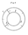
- Figure 4 a typical example of a conventional mechanical seal for hermetically sealing a shaft periphery of a pump for recirculating a cooling water to an automotive engine is shown in Figure 4 which has a housing 1 for a shaft seal portion of a cooling water pump and a rotary shaft 2 inserted into an axial hole 11 of the housing 1 for rotating an impeller around its axis.
- a mechanical seal generally indicated by reference numeral 4 includes, as a part group on the stationary side, an annular case 41 which is hermetically inserted into an opening of the axial hole 11 of the housing 1, a stationary side sliding ring 42 which is supported in an opening portion of the case 41 to be axially movable but prevented from rotating, an elastomer bellows 43 for maintaining a sealed condition between the stationary side sliding ring 42 and the case 41, and a coil spring 44 for biasing in the axial direction to urge the sliding ring 42 away from the case 41.
- a rotary side part group of the mechanical seal 4 includes a sleeve 45 attached around the rotary shaft 2 under the condition that the sleeve 45 is inserted into an interior of the case 41, an elastomer gasket 46 attached to an inner surface of a flanged receiver portion 45a formed at one end of the sleeve 45, and a rotary side sliding ring 47 which fits in the elastomer gasket 46 and faces, in the axial direction, the stationary side sliding ring 42.
- the confronting end faces of the stationary and rotary sliding rings 42 and 47 are brought into intimate contact with each other by the biasing force of the coil spring 44 to form a hermetically seal sliding surface S.
- An engine cooling water A, to be sealed, filled in a pump chamber provided around the sliding rings is prevented from leaking from between the axial hole 11 and the rotary shaft 2 to a bearing (not shown).
- the cup-shaped elastomer gasket 46 which comes into intimate contact with an outer circumferential surface 47a and a bottom surface 47b of the rotary side sliding ring 47 is arranged so as to considerably reduce a contact area of the rotary side sliding ring 47 with the engine cooling water A therearound, and a thermal conductive efficiency of the elastomer gasket 46 is extremely low. Accordingly, it would be difficult to satisfactorily cool the rotary side sliding ring 47 with the cooling water A.
- the seal sliding surface S is likely to be heated to a high temperature, which would degrade the lubricating property to further induce abnormal heats so that an abnormal wear of the seal sliding surface S would be caused and the elastomer gasket 46 would be degraded to deteriorate the sealability at an early stage.
- the rotary side sliding ring 47 is mounted on the outer circumferential surface of the rotary shaft 2 through an elastomer gasket 48 which is brought into intimate contact with the rotary shaft 2 at its inner circumferential surface and at the same time brought into contact with the boss portion of the impeller 3 on its back surface.
- the outer circumferential surface 47a and its adjacent portion of the rotary side sliding ring 47 are completely exposed in the engine cooling water A. With such an arrangement, it would be possible to enhance the cooling efficiency of the rotary side sliding ring 47.
- an object of the present invention is to provide a mechanical seal in which damage due to cracks of the rotary side sliding ring is reduced or prevented and at the same time, the heat radiation performance is enhanced.
- a mechanical seal has a metal plated film layer over a full circumference of a surface of a rotary side sliding ring which is exposed in a liquid to be sealed.
- a like metal plated film layer be formed also on a stationary side sliding ring in the same way.
- the rotary side sliding ring Since in the rotary side sliding ring, a full outer surface formed with the metal plated film layer is brought into contact with a liquid to be sealed, the rotary side sliding ring is effectively cooled to thereby prevent an excessive heat caused by a friction heat generated in the seal sliding surface. Even if any cracks extending radially transversely in the rotary side sliding ring would be caused due to heat at two or more positions, the metal plated film layer for bundling the outer surface prevents the splash of crack pieces caused by the centrifugal force. Also, there is a fear that such cracks would be caused in the stationary side sliding ring, but a like metal plated film layer may be formed on the stationary side sliding ring to thereby prevent the explosion of the crack pieces.
- Reference numeral 1 denotes a housing for a shaft seal portion of an engine cooling water pump.
- Reference numeral 2 denotes a rotary shaft for rotating an impeller 3.
- Reference numeral 5 denotes a mechanical seal to which the present invention pertains.
- the mechanical seal 5 includes, as a stationary side part group, an annular case 51 hermetically engaged with an opening portion of an axial hole 11 of the housing 1, a stationary side sliding ring 52 supported at the opening portion of the case 51, an elastomer bellows 53 brought at both ends into intimate contact with the stationary side sliding ring 52 and the case 51 and which are extendable in the axial direction, and a coil spring 54 for biasing in the axial direction to urge the sliding ring 52 out of the case 51.
- a projection 51 a bent radially outwardly and extending in the axial direction is formed in an inner circumferential sleeve portion of the case 51.
- a cutaway portion 52a extending in the axial direction is formed in the inner circumferential surface of the stationary side sliding ring 52.
- the rotary side part group includes an elastomer gasket 55, and a rotary side sliding ring 56 which is mounted on the outer periphery of the rotary shaft 2 and supported on its back surface by the impeller 3 through the gasket 55 and faces the stationary side sliding ring 52 in the axial direction.
- the non-rotatable stationary side sliding ring 52 is brought, by the spring force of the coil spring 54, into contact with a confronting end face of the rotary side sliding ring 56 to be rotated together with rotary shaft 2 and impeller 3 to thereby form a hermetical sliding surface S to prevent the engine cooling water A therearound from leaking.
- the elastomer gasket 55 has an inner sleeve portion 55a and a radially outwardly extending flanged portion 55b.
- the elastomer gasket 55 has an L-shaped cross section taken along a phantom plane passing through a centerline O.
- the inner sleeve portion 55a is interposed between the outer circumferential surface of the rotary shaft 2 and the inner circumferential surface of the stationary side sliding ring 56, whereas the radially outwardly extending flanged portion 55b is interposed between the boss portion of the impeller 3 and the back surface of the rotary side sliding ring 56.
- a continuous projection 55c be provided in the circumferential direction to locally increase an area of parts to be deformed to enhance the sealability and a pressure contact force.
- the rotary side sliding ring 56 is made of hard materials in comparison with the stationary side sliding ring 52, i.e., ceramics such as SiC.
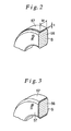
- a thin metal plated film layer 57 is formed over a full circumference of the outer surface 56b of the sliding ring 56 in the form of a ribbon by electrolytic deposition as shown in Figure 2.
- the centrifugal force to be applied to the rotary side sliding ring 56 changes depending upon a mass determined by a material and dimensions such as an inner diameter and outer diameter of the rotary side sliding ring 56 and an RPM of the rotary shaft.
- a film thickness t or a film width w of the metal plated film layer 57 are suitably selected in view of these parameters so as to ensure such a tension strength that the splash of the radially transversal cracks in the rotary side sliding ring 56 may be prevented and the crack pieces may be restricted. According to the simulation made by the inventors, it is found that a sufficient strength may be obtained with a film thickness of several hundreds of microns.
- the stationary side sliding ring 52 is made of fragile material such as carbon, there is a fear that a crack would be caused due to heat. Since the sliding ring 52 is not rotated, there is no fear that the crack piece is splashed by the centrifugal force. However, since the caused crack further open wider due to vibration or pressure or is exploded by gravity, a large amount of the cooling water would leak. It is therefore preferable to apply the metal plated film layer 57 over all the surface of the stationary sliding ring 52 other than the seal sliding surface S in the same manner as rotary side sliding ring 56.
- the rotary side sliding ring is effectively cooled by the liquid to be sealed, it is possible to prevent the insufficient lubrication of the seal sliding surface caused by the excessive heat and to prevent the abnormal wear caused by the insufficient lubrication to thereby prolong a service life of the mechanical seal. Even if the sliding ring would have thermal cracks, it is possible to prevent the splash of the crack pieces by the metal plated film layer formed on the outer surface. It is therefore possible to prevent any leakage of a large amount of liquid caused by the elimination of the seal sliding surface.
Landscapes
- Engineering & Computer Science (AREA)
- General Engineering & Computer Science (AREA)
- Mechanical Engineering (AREA)
- Mechanical Sealing (AREA)
- Gasket Seals (AREA)
Applications Claiming Priority (2)
| Application Number | Priority Date | Filing Date | Title |
|---|---|---|---|
| JP4327612A JPH06159520A (ja) | 1992-11-13 | 1992-11-13 | メカニカルシール |
| JP327612/92 | 1992-11-13 |
Publications (1)
| Publication Number | Publication Date |
|---|---|
| EP0597615A1 true EP0597615A1 (de) | 1994-05-18 |
Family
ID=18201003
Family Applications (1)
| Application Number | Title | Priority Date | Filing Date |
|---|---|---|---|
| EP93308721A Withdrawn EP0597615A1 (de) | 1992-11-13 | 1993-11-01 | Gleitringdichtung |
Country Status (3)
| Country | Link |
|---|---|
| EP (1) | EP0597615A1 (de) |
| JP (1) | JPH06159520A (de) |
| KR (1) | KR940011827A (de) |
Cited By (4)
| Publication number | Priority date | Publication date | Assignee | Title |
|---|---|---|---|---|
| EP0721079A1 (de) * | 1995-01-04 | 1996-07-10 | FEODOR BURGMANN DICHTUNGSWERKE GmbH & Co. | Gleitring in Verbundbauweise einer Gleitringdichtung |
| EP0779457A1 (de) * | 1995-12-15 | 1997-06-18 | Federal-Mogul Burscheid GmbH | Gleitringdichtung |
| DE19637813A1 (de) * | 1996-09-17 | 1998-04-02 | Freudenberg Carl Fa | Gleitringdichtung |
| EP0845622A3 (de) * | 1996-11-29 | 1999-07-07 | FEODOR BURGMANN DICHTUNGSWERKE GmbH & Co. | Gleitringdichtungsanordnung für hohe Umlaufgeschwindigkeiten |
Families Citing this family (2)
| Publication number | Priority date | Publication date | Assignee | Title |
|---|---|---|---|---|
| JPWO2016088625A1 (ja) * | 2014-12-03 | 2017-10-12 | イーグルブルグマンジャパン株式会社 | ダイアフラム形分割メカニカルシール |
| KR102153713B1 (ko) | 2018-11-29 | 2020-09-10 | (주)윈윈 | Co2 마이크로 버블링 장치를 이용한 비숍 스크러버 집진수 고(高)페하 중화 장치 및 이를 구비한 고로가스 청정 시스템 |
Citations (3)
| Publication number | Priority date | Publication date | Assignee | Title |
|---|---|---|---|---|
| EP0026631A1 (de) * | 1979-09-25 | 1981-04-08 | J.H. Fenner & Co. Limited | Drehende Stirnseitendichtungen |
| EP0237704A2 (de) * | 1986-01-13 | 1987-09-23 | RHEINHÜTTE GmbH & Co. | Schichtkörper, insbesondere aus Siliziumcarbid und Nickel |
| EP0484305A2 (de) * | 1990-10-31 | 1992-05-06 | ITT INDUSTRIES, INC. (a Delaware corporation) | Hochgeschwindigkeitspumpe für Wirbelbäder |
-
1992
- 1992-11-13 JP JP4327612A patent/JPH06159520A/ja not_active Withdrawn
-
1993
- 1993-11-01 EP EP93308721A patent/EP0597615A1/de not_active Withdrawn
- 1993-11-11 KR KR1019930023866A patent/KR940011827A/ko not_active Ceased
Patent Citations (3)
| Publication number | Priority date | Publication date | Assignee | Title |
|---|---|---|---|---|
| EP0026631A1 (de) * | 1979-09-25 | 1981-04-08 | J.H. Fenner & Co. Limited | Drehende Stirnseitendichtungen |
| EP0237704A2 (de) * | 1986-01-13 | 1987-09-23 | RHEINHÜTTE GmbH & Co. | Schichtkörper, insbesondere aus Siliziumcarbid und Nickel |
| EP0484305A2 (de) * | 1990-10-31 | 1992-05-06 | ITT INDUSTRIES, INC. (a Delaware corporation) | Hochgeschwindigkeitspumpe für Wirbelbäder |
Cited By (5)
| Publication number | Priority date | Publication date | Assignee | Title |
|---|---|---|---|---|
| EP0721079A1 (de) * | 1995-01-04 | 1996-07-10 | FEODOR BURGMANN DICHTUNGSWERKE GmbH & Co. | Gleitring in Verbundbauweise einer Gleitringdichtung |
| EP0779457A1 (de) * | 1995-12-15 | 1997-06-18 | Federal-Mogul Burscheid GmbH | Gleitringdichtung |
| DE19637813A1 (de) * | 1996-09-17 | 1998-04-02 | Freudenberg Carl Fa | Gleitringdichtung |
| DE19637813C2 (de) * | 1996-09-17 | 2001-12-06 | Freudenberg Carl Fa | Gleitringdichtung |
| EP0845622A3 (de) * | 1996-11-29 | 1999-07-07 | FEODOR BURGMANN DICHTUNGSWERKE GmbH & Co. | Gleitringdichtungsanordnung für hohe Umlaufgeschwindigkeiten |
Also Published As
| Publication number | Publication date |
|---|---|
| JPH06159520A (ja) | 1994-06-07 |
| KR940011827A (ko) | 1994-06-22 |
Similar Documents
| Publication | Publication Date | Title |
|---|---|---|
| US7722050B2 (en) | Mechanical seal bearing protector | |
| US5984316A (en) | Rotary reciprocating seals with internal metal band | |
| US6322081B1 (en) | Circumferential seal with ceramic rotor | |
| EP0547652A1 (de) | Wasserpumpe | |
| US5183270A (en) | Composite seal rotor | |
| US2883212A (en) | Labyrinth type magnetic rotary seal | |
| EP0597615A1 (de) | Gleitringdichtung | |
| US20210172528A1 (en) | Face seal with welded bellows | |
| JPH08270801A (ja) | パッキンリング | |
| US20110084454A1 (en) | Internally pressurized seals | |
| GB2076480A (en) | Shaft | |
| CN110906007A (zh) | 一种航空油冷发电机用机械密封结构 | |
| US5340121A (en) | Face seal with integral fluorocarbon polymer bellows | |
| US7237961B2 (en) | Rolling bearing | |
| US5947070A (en) | Molded plastic camshaft with seal ring | |
| EP3742027A1 (de) | Dichtungsstruktur und dichtung zur verwendung darin | |
| US8011668B2 (en) | Close coupled mechanical seal | |
| JPH09133217A (ja) | リップ型シール | |
| US4384727A (en) | Circumferential ring seal assembly | |
| JPH11236977A (ja) | 回転軸シール | |
| US12006979B2 (en) | Bearing seat assembly | |
| JP4120816B2 (ja) | 密封装置 | |
| RU2017977C1 (ru) | Поршневая машина и способ ее сборки | |
| WO2026049926A1 (en) | Seal cartridge, seal cartridge assembly, and method of use | |
| CA1130272A (en) | Drive system for a ceramic regenerator |
Legal Events
| Date | Code | Title | Description |
|---|---|---|---|
| PUAI | Public reference made under article 153(3) epc to a published international application that has entered the european phase |
Free format text: ORIGINAL CODE: 0009012 |
|
| AK | Designated contracting states |
Kind code of ref document: A1 Designated state(s): DE FR GB NL |
|
| 17P | Request for examination filed |
Effective date: 19941031 |
|
| 17Q | First examination report despatched |
Effective date: 19960219 |
|
| 18D | Application deemed to be withdrawn |
Effective date: 19960702 |