EP0597713B1 - Steuereinheit für hochverdichtende Motoren unter Verwendung von verdampfenden Kraftstoffen - Google Patents
Steuereinheit für hochverdichtende Motoren unter Verwendung von verdampfenden Kraftstoffen Download PDFInfo
- Publication number
- EP0597713B1 EP0597713B1 EP93309032A EP93309032A EP0597713B1 EP 0597713 B1 EP0597713 B1 EP 0597713B1 EP 93309032 A EP93309032 A EP 93309032A EP 93309032 A EP93309032 A EP 93309032A EP 0597713 B1 EP0597713 B1 EP 0597713B1
- Authority
- EP
- European Patent Office
- Prior art keywords
- control valve
- engine
- load
- chamber
- fuel
- Prior art date
- Legal status (The legal status is an assumption and is not a legal conclusion. Google has not performed a legal analysis and makes no representation as to the accuracy of the status listed.)
- Expired - Lifetime
Links
Images


Classifications
-
- F—MECHANICAL ENGINEERING; LIGHTING; HEATING; WEAPONS; BLASTING
- F02—COMBUSTION ENGINES; HOT-GAS OR COMBUSTION-PRODUCT ENGINE PLANTS
- F02D—CONTROLLING COMBUSTION ENGINES
- F02D41/00—Electrical control of supply of combustible mixture or its constituents
- F02D41/30—Controlling fuel injection
- F02D41/38—Controlling fuel injection of the high pressure type
-
- F—MECHANICAL ENGINEERING; LIGHTING; HEATING; WEAPONS; BLASTING
- F02—COMBUSTION ENGINES; HOT-GAS OR COMBUSTION-PRODUCT ENGINE PLANTS
- F02B—INTERNAL-COMBUSTION PISTON ENGINES; COMBUSTION ENGINES IN GENERAL
- F02B19/00—Engines characterised by precombustion chambers
- F02B19/02—Engines characterised by precombustion chambers the chamber being periodically isolated from its cylinder
-
- F—MECHANICAL ENGINEERING; LIGHTING; HEATING; WEAPONS; BLASTING
- F02—COMBUSTION ENGINES; HOT-GAS OR COMBUSTION-PRODUCT ENGINE PLANTS
- F02D—CONTROLLING COMBUSTION ENGINES
- F02D35/00—Controlling engines, dependent on conditions exterior or interior to engines, not otherwise provided for
- F02D35/02—Controlling engines, dependent on conditions exterior or interior to engines, not otherwise provided for on interior conditions
- F02D35/025—Controlling engines, dependent on conditions exterior or interior to engines, not otherwise provided for on interior conditions by determining temperatures inside the cylinder, e.g. combustion temperatures
-
- F—MECHANICAL ENGINEERING; LIGHTING; HEATING; WEAPONS; BLASTING
- F02—COMBUSTION ENGINES; HOT-GAS OR COMBUSTION-PRODUCT ENGINE PLANTS
- F02D—CONTROLLING COMBUSTION ENGINES
- F02D41/00—Electrical control of supply of combustible mixture or its constituents
- F02D41/0025—Controlling engines characterised by use of non-liquid fuels, pluralities of fuels, or non-fuel substances added to the combustible mixtures
- F02D41/003—Adding fuel vapours, e.g. drawn from engine fuel reservoir
-
- F—MECHANICAL ENGINEERING; LIGHTING; HEATING; WEAPONS; BLASTING
- F02—COMBUSTION ENGINES; HOT-GAS OR COMBUSTION-PRODUCT ENGINE PLANTS
- F02B—INTERNAL-COMBUSTION PISTON ENGINES; COMBUSTION ENGINES IN GENERAL
- F02B1/00—Engines characterised by fuel-air mixture compression
- F02B1/02—Engines characterised by fuel-air mixture compression with positive ignition
- F02B1/04—Engines characterised by fuel-air mixture compression with positive ignition with fuel-air mixture admission into cylinder
-
- F—MECHANICAL ENGINEERING; LIGHTING; HEATING; WEAPONS; BLASTING
- F02—COMBUSTION ENGINES; HOT-GAS OR COMBUSTION-PRODUCT ENGINE PLANTS
- F02B—INTERNAL-COMBUSTION PISTON ENGINES; COMBUSTION ENGINES IN GENERAL
- F02B1/00—Engines characterised by fuel-air mixture compression
- F02B1/12—Engines characterised by fuel-air mixture compression with compression ignition
-
- F—MECHANICAL ENGINEERING; LIGHTING; HEATING; WEAPONS; BLASTING
- F02—COMBUSTION ENGINES; HOT-GAS OR COMBUSTION-PRODUCT ENGINE PLANTS
- F02B—INTERNAL-COMBUSTION PISTON ENGINES; COMBUSTION ENGINES IN GENERAL
- F02B19/00—Engines characterised by precombustion chambers
- F02B2019/006—Engines characterised by precombustion chambers with thermal insulation
-
- F—MECHANICAL ENGINEERING; LIGHTING; HEATING; WEAPONS; BLASTING
- F02—COMBUSTION ENGINES; HOT-GAS OR COMBUSTION-PRODUCT ENGINE PLANTS
- F02B—INTERNAL-COMBUSTION PISTON ENGINES; COMBUSTION ENGINES IN GENERAL
- F02B3/00—Engines characterised by air compression and subsequent fuel addition
- F02B3/06—Engines characterised by air compression and subsequent fuel addition with compression ignition
- F02B3/08—Methods of operating
-
- F—MECHANICAL ENGINEERING; LIGHTING; HEATING; WEAPONS; BLASTING
- F02—COMBUSTION ENGINES; HOT-GAS OR COMBUSTION-PRODUCT ENGINE PLANTS
- F02D—CONTROLLING COMBUSTION ENGINES
- F02D41/00—Electrical control of supply of combustible mixture or its constituents
- F02D41/30—Controlling fuel injection
- F02D41/3011—Controlling fuel injection according to or using specific or several modes of combustion
- F02D41/3017—Controlling fuel injection according to or using specific or several modes of combustion characterised by the mode(s) being used
- F02D41/3035—Controlling fuel injection according to or using specific or several modes of combustion characterised by the mode(s) being used a mode being the premixed charge compression-ignition mode
-
- Y—GENERAL TAGGING OF NEW TECHNOLOGICAL DEVELOPMENTS; GENERAL TAGGING OF CROSS-SECTIONAL TECHNOLOGIES SPANNING OVER SEVERAL SECTIONS OF THE IPC; TECHNICAL SUBJECTS COVERED BY FORMER USPC CROSS-REFERENCE ART COLLECTIONS [XRACs] AND DIGESTS
- Y02—TECHNOLOGIES OR APPLICATIONS FOR MITIGATION OR ADAPTATION AGAINST CLIMATE CHANGE
- Y02T—CLIMATE CHANGE MITIGATION TECHNOLOGIES RELATED TO TRANSPORTATION
- Y02T10/00—Road transport of goods or passengers
- Y02T10/10—Internal combustion engine [ICE] based vehicles
- Y02T10/12—Improving ICE efficiencies
Definitions
- the present invention relates to the control unit for high-compression-ratio engines whereby volatile liquid fuel is burnt at high compression ratios.
- an object of the invention is to provide a control unit for the said engines which improves the combustion efficiency by providing a subcombustion chamber with a control valve to burn volatile fuels at high compression ratios, and by controlling the opening/closing of the control valve according to the engine load and the temperature of the subcombustion chamber.
- US-A-4372264 discloses an internal combustion engine which is spark-ignited and having a fuel vaporiser chamber.
- EP-A-0503973 discloses an internal combustion engine having swirl chambers.
- a high-compression-ratio engine using vaporizing fuels comprising:
- the control valve is mounted on the path between the main chamber and the subcombustion chamber where the precombustion of volatile liquid fuels takes place.
- the fuel is preferably injected into the subcombustion chamber with the control valve closed.
- the air-fuel mixture is activated by the temperature of the inner wall of the subcombustion chamber, so that self-ignition takes place by the temperature of the inner wall. If the temperature is low, the fuel may be ignited by the spark plug.
- the control valve may be opened at the initial stage of the expansion stroke. When the control valve is closed at the final stage of expansion, the unburnt hot exhaust gases remain in the subcombustion chamber, whereby the injection fuel in the next cycle will be activated. If a full load is applied to the engine, the control valve may be closed in the exhaust stroke. The high exhaust pressure allows the hot exhaust gases to remain in the subcombustion chamber, even when the control valve is closed. Thus, the injection fuel in the next cycle may be activated, resulting in a high-compression-ratio engine with highly efficient combustion.
- control valve opening in use the control valve at a specified time during the compression stroke and immediately closing the control valve if a large load is applied to the engine.
- Fig. 1 is a block diagram showing a configuration example of high-compression-ratio engines using vaporizing fuels according to the invention.
- the cylinder 1 is equipped with the piston 2 that freely slides in the vertical direction.
- the cylinder head 11 has the subcombustion chamber 3, which is used as a precombustion chamber for volatile petrol and methanol, and intake and exhaust valves 4.
- the piston head 21 uses ceramics with high strength and heat resistance.
- the top of the piston head is formed into a low slant at subcombustion chamber side.
- the portion corresponding to the path 31 to the subcombustion chamber 3 has the hollow 22 to serve as an air reservoir, which together with the upper gap of the piston 2 forms the main combustion chamber 23.
- the subcombustion chamber 3 is made of ceramics with high strength, heat resistance and high thermal insulation, as with, for example, silicon nitride.
- the air layer 32 for heat insulation is formed around the outer wall of the subcombustion chamber.
- the center of the subcombustion chamber is equipped with the control valve 5 that opens/closes the path 31 by moving vertically.
- the stem 51 of the control valve 5 is supported by the shaft hole 33 in the upper wall of the subcombustion chamber.
- the adsorption plate 52 installed on the top of the stem opens/closes the path 31 by its suction force through control of power supply to the electromagnetic mechanism 34 located in the upper portion of the subcombustion chamber 3.
- the heat insulator 35 is installed between the subcombustion chamber 3 and the electromagnetic mechanism 34.
- the injection nozzle 6 is installed to the side wall of the subcombustion chamber 3 to inject the volatile fuel from the injection pump 61 to the subcombustion chamber.
- the spark plug 7 ignites the fuel by spark discharge, which is used when ignition is difficult because of the condition of the engine load or low temperature of the inner wall of the subcombustion chamber 3.
- the controller 8 consists of a microcomputer. The controller performs the specified operation when the detection signals are input from the revolution sensor 81, the load sensor 82 and the crankshaft position sensor 83 of the engine. Then, operation instructions are issued to the electromagnetic mechanism 34, the injection pump or the spark plug 7 according to the map and the control procedure stored in the controller.
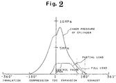
- Fig. 2 is a curve diagram showing the relation between the crank angle employed in the embodiment and the opening/closing of the control valve.
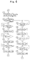
- Fig. 3 and 4 are flowcharts showing an example of the operations of the embodiment. The operations of the embodiment will be explained herebelow in detail with reference to these drawings.
- step 1 in Fig. 3 the engine revolution signal from the revolution sensor 81, the engine load signal from the load sensor 82 and the position signal from the crankshaft position sensor 83 are input to the controller, respectively.
- the controller verifies these signals and proceed to step 3 if it detects that the load is applied to part of the engine at step 2. If the load is larger than the specified load La, the controller goes to step 15 in Fig. 4.
- step 3 fuel injection and the ignition timing are determined, based on the map stored in the controller. Then, the controller proceeds to step 4 to inject fuel from the injection nozzle 6.
- step 7 the controller opens the control valve 5 by using the electromagnetic mechanism 34 at the point when the crank angle in the compression stroke reaches ⁇ ° (BTDC 30° to 0 ° ) near the top dead center. Then, air is supplied from the main combustion chamber in the compression stroke for combustion, and blown into the main combustion chamber (step 8). If the crank angle in the expansion stroke reaches ⁇ e (BBDC 30° to ABDC 20° ), the control valve 5, which was open, will be closed, and the engine will be operated over the period from the expansion to exhaust strokes (steps 9 and 10).
- step 5 If the temperature of the inner wall of the subcombustion chamber 3 is too high in the said step 5, the controller goes to step 11. In such a case, the high temperature causes self-ignition in the subcombustion chamber.
- steps 12 to 14 The same operations (steps 12 to 14) as in the subsequent steps of the said step 8 will be performed by opening the control valve 4 when the crank angle reaches ⁇ ° near the top dead center.
- step 15 fuel injection and the ignition timing are determined according to that engine load. Then, in step 16, the temperature of the inner wall of the subcombustion chamber 3 is verified. If the temperature exceeds the specified temperature Ta2, the controller proceeds to step 17. In the case of the compression stroke, the fuel is injected from the injection nozzle 6 to be ignited by the temperature of the inner wall (step 18).
- step 19 the power is supplied to the electromagnetic mechanism 34 to open the control valve 5 at the point when the crankshaft angle reaches the specified angle of ⁇ 2 ° near the top dead center. Then, the control valve 5 is closed at the specified angle of ⁇ e1 in the exhaust stroke (steps 20 to 22). As shown in Fig. 2, the closing timing of the control valve in step 19 is specified as delayed from the closing timing when the engine is partially loaded.
- step 16 If the wall temperature of the subcombustion chamber 3 is low in step 16, the controller proceeds to steps 23 and then to 24 to perform injection of the fuel. Since self-ignition does not take place in low wall temperature, the fuel is ignited by using the spark plug 7 in step 25.
- step 27 the control valve 5 is opened at the point when the crankshaft angle reaches ⁇ 3 ° which is delayed from the timing specified at ⁇ 2 ° in the said step 19.
- step 28 the control valve 5 is closed at the point when the crank angle reaches the specified angle of ⁇ e2 in the exhaust stroke, and thus the operation of the engine will be continued.
- the subcombustion chamber where the precombustion of volatile fuel takes place has a heat-insulating structure so that the temperature of the inner wall of the subcombustion chamber increases.
- the control valve is installed to the path between the main and subcombustion chambers. The fuel is injected into the subcombustion chamber with the control valve closed, and the fuel is ignited through self-ignition using the temperature of the inner wall, or by using the spark plug if the temperature is low. The air-fuel mixture ignited in the subcombustion chamber is blown into the main combustion chamber for combustion by opening the control valve at the specified angle around the top dead center according to the load applied to the engine.
- control valve opened at the initial stage of the expansion stroke is closed at the final stage of expansion to accumulate unburnt hot gases in the subcombustion chamber when the load is applied to part of the engine, so that the fuel for the next - injection - cycle will be vaporized and activated.
- the control valve is closed in the exhaust stroke when the load is applied to the entire engine. Since the exhaust pressure is high, hot exhaust gases remain in the subcombustion chamber even when the control valve is closed. As a result, the fuel in the next injection is vaporized and activated with high efficiency. Therefore, volatile liquid fuel can be burn with high efficiency at high compression ratios, without causing premature ignition or knocking.
- FIG. is a flow chart of the second embodiment.
- step 31 in Fig.5 the number of rotation of engine, the engine load, and the crankshaft positioned of the detection signals are inputed from the revolution sensor, load sensor 82 and crankshaft positioned sensor 83. After this, the engine load which is input in step.32 is checked.
- step 33 fuel injection and the ignition timing are determined.
- step 34 the controller ignites fuel at the determined time.
- step 35 the spark plug 7 ignites the fuel by spark disc and then power is supplied to the electromagnetic mechanism 34 to open the control valve 5 near the top dead center.
- the engine load is small and generates plenty of surplus air.
- the combustion of air-fuel mixture by ignition makes the pressure in the subcombustion chamber high and also makes it possible to open the electromagnetic mechanism 34 even when the electromagnetic power is small.
- step 37 If the load applied to the engine is large in the said step 32, the controller proceeds to step 37 and is verified if it is the compression stroke. In the case of compression stroke, the controller goes to step 38. As shown in FIG. 6, after the control valve is opened at the specified timing of the compression stroke, it is closed immediately in step 39 and fuel injection is performed. Then, the fuel is ignited by using the spark plug 7 and the control valve is opened near the top dead center (step 40 to 42) In this case, by opening the control valve in the compression stroke, a large quantity of air flows into the subcombustion chamber from the main combustion chamber. The mixture of air and sparked fuel makes it active and by igniting this, the pressure in the subcombustion chamber is increased to make it easy to open the control valve 5.
- step 33 the check is performed to verify if it is the exhaust stroke, and in the case of exhaust stroke, it closes the control valve 5 and go back to the first flow.
- a curve diagram in fig.6 shows the pressure in the subcombustion chamber from the compression stroke to exhaust stroke.
- the ignition is well performed even with the high compression ratio. And when the load is high, the pressure in the subcombustion is increased by introducing air into the subcombustion through the open/close of the control valve and igniting fuel with the injection. As a result, the difference in pressure between the main combustion and the subcombustion chamber is decreased. Therefore even with the small driving force, the control valve can be opened.
Landscapes
- Engineering & Computer Science (AREA)
- Chemical & Material Sciences (AREA)
- Combustion & Propulsion (AREA)
- Mechanical Engineering (AREA)
- General Engineering & Computer Science (AREA)
- Combustion Methods Of Internal-Combustion Engines (AREA)
- Output Control And Ontrol Of Special Type Engine (AREA)
Claims (5)
- Motor mit hohem Kompressionsverhältnis, bei welchem Verdampfungsbrennstoffe verwendet werden, wobei der Motor folgendes umfaßt:eine Hauptverbrennungskammer (23) und eine wärmeisolierte Nebenverbrennungskammer (3), in der eine Vorverbrennung stattfindet;ein Steuerventil (5), das einen Weg (31) zwischen der Hauptverbrennungskammer (23) und der Nebenverbrennungskammer (3) öffnet/schließt;eine Einspritzdüse (6), die flüchtigen flüssigen Brennstoff in die Nebenverbrennungskammer (3) einspritzt;eine Zündkerze (7), die in der Nebenverbrennungskammer (3) eingesetzt ist und den eingespritzten Brennstoff zündet; undMittel (8) zur Steuerung des Öffnens/Schließens des Steuerventils (5), welche in Verwendung das Steuerventil zwischen der Endphase des Expansionshubs und dem Anfang des Auslaßhubs schließen; gekennzeichnet durch:Mittel (8), die in Verwendung das Steuerventil (5) in der Anfangsphase des Expansionshubs in Übereinstimmung mit dem Zustand der auf den Motor ausgeübten Last öffnen.
- Motor nach Anspruch 1, welcher ferner Mittel (8) zum Schließen des Steuerventils (5) in der Endphase des Expansionshubs umfaßt, wenn eine Teillast auf den Motor ausgeübt wird, und am Anfang des Auslaßhubs, wenn eine volle Last auf den Motor ausgeübt wird.
- Motor nach Anspruch 1 oder Anspruch 2, welcher ferner Mittel (8) zur Steuerung der Zündung der Zündkerze (7) umfaßt, beruhend auf dem Verhältnis zwischen der Motorlast und der Temperatur der Innenwand der Nebenverbrennungskammer (3).
- Motor nach einem der Ansprüche 1 bis 3, umfassend Mittel (8), die in Verwendung das Steuerventil (5) zu einem bestimmten Zeitpunkt während des Kompressionshubs öffnen und das Steuerventil (5) sofort schließen, wenn eine große Last auf den Motor ausgeübt wird.
- Motor nach einem der Ansprüche 1 bis 4, umfassend einen elektromagnetischen Mechanismus (34) zum Öffnen des Steuerventils (5) durch eine elektromagnetische Kraft.
Applications Claiming Priority (4)
| Application Number | Priority Date | Filing Date | Title |
|---|---|---|---|
| JP32605692A JP3148813B2 (ja) | 1992-11-11 | 1992-11-11 | 気化燃料用高圧縮比エンジンの制御装置 |
| JP326057/92 | 1992-11-11 | ||
| JP326056/92 | 1992-11-11 | ||
| JP4326057A JP3065826B2 (ja) | 1992-11-11 | 1992-11-11 | 気化燃料用高圧縮比エンジンの制御装置 |
Publications (3)
| Publication Number | Publication Date |
|---|---|
| EP0597713A2 EP0597713A2 (de) | 1994-05-18 |
| EP0597713A3 EP0597713A3 (en) | 1994-07-20 |
| EP0597713B1 true EP0597713B1 (de) | 1997-05-14 |
Family
ID=26572061
Family Applications (1)
| Application Number | Title | Priority Date | Filing Date |
|---|---|---|---|
| EP93309032A Expired - Lifetime EP0597713B1 (de) | 1992-11-11 | 1993-11-11 | Steuereinheit für hochverdichtende Motoren unter Verwendung von verdampfenden Kraftstoffen |
Country Status (3)
| Country | Link |
|---|---|
| US (1) | US5826558A (de) |
| EP (1) | EP0597713B1 (de) |
| DE (1) | DE69310674T2 (de) |
Cited By (1)
| Publication number | Priority date | Publication date | Assignee | Title |
|---|---|---|---|---|
| DE102018210808A1 (de) | 2018-06-29 | 2020-01-02 | Mtu Friedrichshafen Gmbh | Vorkammer-Anordnung für eine Brennkraftmaschine, Brennkraftmaschine mit einer solchen Vorkammer-Anordnung, und Verfahren zum Betreiben einer solchen Brennkraftmaschine |
Families Citing this family (13)
| Publication number | Priority date | Publication date | Assignee | Title |
|---|---|---|---|---|
| DE19624964A1 (de) * | 1996-06-22 | 1998-01-02 | Motoren Werke Mannheim Ag | Zündsystem für einen Gasmotor |
| DE19624965A1 (de) * | 1996-06-22 | 1998-01-02 | Motoren Werke Mannheim Ag | Zündsystem für einen Gasmotor |
| RU2171384C1 (ru) * | 2000-04-10 | 2001-07-27 | Гурьянов Александр Владимирович | Способ работы двигателя внутреннего сгорания |
| US6953020B2 (en) * | 2003-10-07 | 2005-10-11 | Robert Bosch Gmbh | Control of auto-ignition timing for combustion in piston engines by prechamber compression ignition |
| PL364958A1 (en) * | 2004-02-09 | 2005-08-22 | Wiesław Wiatrak | Exhaust gas recirculation assisted fuel injection system |
| MA31723B1 (fr) * | 2009-01-30 | 2010-10-01 | Nasserlehaq Nsarellah | Chambre de combustion auxiliaire avec soupape pour un rapport de compression volumetrique variable chez les moteurs a combustion interne de quatre temps |
| US8985089B2 (en) * | 2012-07-25 | 2015-03-24 | The United States Of America, As Represented By The Administrator Of The U.S. Environmental Protection Agency | Low temperature dual fuel combustion utilizing diesel and methanol fuels |
| WO2015110257A2 (de) * | 2014-01-21 | 2015-07-30 | Peter Kreuter | Hubkolbenbrennkraftmaschine sowie verfahren zum betreiben einer hubkolbenbrennkraftmaschine |
| US10273869B2 (en) * | 2016-10-14 | 2019-04-30 | Caterpillar Inc. | Prechamber ignition device for internal combustion engine, and method |
| US11085402B1 (en) * | 2020-04-01 | 2021-08-10 | Ford Global Technologies, Llc | Methods and systems for operating an adjustable pre-chamber |
| US11156149B1 (en) * | 2020-09-11 | 2021-10-26 | Ford Global Technologies, Llc | Systems and methods for a variable volume pre-chamber igniter |
| US11156147B1 (en) * | 2020-12-02 | 2021-10-26 | Aramco Services Company | Prechamber device for internal combustion engine |
| US11378002B1 (en) * | 2021-04-16 | 2022-07-05 | Ford Global Technologies, Llc | Systems and methods for adjustable pre-chamber |
Family Cites Families (9)
| Publication number | Priority date | Publication date | Assignee | Title |
|---|---|---|---|---|
| DE2321060A1 (de) * | 1973-04-26 | 1974-11-14 | Volkswagenwerk Ag | Hubkolben-brennkraftmaschine mit innerer kontinuierlicher verbrennung |
| FR2342399A1 (fr) * | 1976-02-24 | 1977-09-23 | Chrysler France | Perfectionnements a un moteur a combustion interne du type diesel |
| US4320727A (en) * | 1979-12-19 | 1982-03-23 | Artman Noel G | Process of fuel stratification within and venting of engine auxiliary combustion chamber |
| US4372264A (en) * | 1979-12-26 | 1983-02-08 | Trucco Horacio A | Internal combustion engine for diverse fuels |
| JPS60195368A (ja) * | 1984-03-17 | 1985-10-03 | Mazda Motor Corp | 渦流室式デイ−ゼルエンジンの排気還流制御装置 |
| JPS623119A (ja) * | 1985-06-28 | 1987-01-09 | Haruyama Jikou:Kk | 圧縮着火機関 |
| JPH0357817A (ja) * | 1989-07-27 | 1991-03-13 | Isuzu Motors Ltd | 副室の断熱構造 |
| JP3047493B2 (ja) * | 1991-03-14 | 2000-05-29 | いすゞ自動車株式会社 | 断熱副室式エンジン |
| US5237964A (en) * | 1992-11-30 | 1993-08-24 | Constantin Tomoiu | Internal combustion engine with a new sequence of operation and combustion |
-
1993
- 1993-11-11 EP EP93309032A patent/EP0597713B1/de not_active Expired - Lifetime
- 1993-11-11 DE DE69310674T patent/DE69310674T2/de not_active Expired - Fee Related
-
1997
- 1997-01-09 US US08/781,043 patent/US5826558A/en not_active Expired - Fee Related
Cited By (2)
| Publication number | Priority date | Publication date | Assignee | Title |
|---|---|---|---|---|
| DE102018210808A1 (de) | 2018-06-29 | 2020-01-02 | Mtu Friedrichshafen Gmbh | Vorkammer-Anordnung für eine Brennkraftmaschine, Brennkraftmaschine mit einer solchen Vorkammer-Anordnung, und Verfahren zum Betreiben einer solchen Brennkraftmaschine |
| DE102018210808B4 (de) | 2018-06-29 | 2022-06-15 | Mtu Friedrichshafen Gmbh | Vorkammer-Anordnung für eine Brennkraftmaschine, Brennkraftmaschine mit einer solchen Vorkammer-Anordnung, und Verfahren zum Betreiben einer solchen Brennkraftmaschine |
Also Published As
| Publication number | Publication date |
|---|---|
| EP0597713A2 (de) | 1994-05-18 |
| EP0597713A3 (en) | 1994-07-20 |
| US5826558A (en) | 1998-10-27 |
| DE69310674T2 (de) | 1997-09-04 |
| DE69310674D1 (de) | 1997-06-19 |
Similar Documents
| Publication | Publication Date | Title |
|---|---|---|
| US5119780A (en) | Staged direct injection diesel engine | |
| US5454356A (en) | Engine with pre-chamber | |
| EP0643209B1 (de) | Verfahren und Brennkraftmaschine mit einer Vorrichtung zum Einbringen von Kraftstoff in eine Zweikraftstoffanordnung mit einer Hybridverbrennung von Diffusion und Vorgemisch | |
| AU653129B2 (en) | Method of combustion for dual fuel engine | |
| US6619254B2 (en) | Method for operating an internal combustion engine operated with a self-ignitable fuel | |
| US6213086B1 (en) | Combustion engine | |
| US5207058A (en) | Internal combustion engine | |
| US4372264A (en) | Internal combustion engine for diverse fuels | |
| US6915776B2 (en) | Premixed charge compression ignition engine with optimal combustion control | |
| US7370629B2 (en) | Method for operating an internal combustion engine with direct fuel injection during a post-start phase | |
| EP0597713B1 (de) | Steuereinheit für hochverdichtende Motoren unter Verwendung von verdampfenden Kraftstoffen | |
| EP0465566A1 (de) | Verbrennungs- und arbeitssystem für eine ottobrennkraftmaschine | |
| JP2004522050A (ja) | 4行程自己点火エンジン | |
| EP1688601B1 (de) | Verbrennungskraftmaschine mit Kompressionszündung und Kraftstoff-Luft Vormischung mit optimaler Verbrennungsregelung | |
| US7044104B2 (en) | Internal combustion engine with compression ignition | |
| US5603298A (en) | High compression ratio internal-combustion engine | |
| JP2002266645A (ja) | エンジン及びその運転方法及び副室機構 | |
| JP4073315B2 (ja) | 副室式エンジン | |
| JP3065826B2 (ja) | 気化燃料用高圧縮比エンジンの制御装置 | |
| JP4086440B2 (ja) | エンジン | |
| US5477822A (en) | Spark ignition engine with cylinder head combustion chamber | |
| JP2006052687A (ja) | 筒内直接噴射式内燃機関 | |
| JP2005076484A (ja) | 自着火エンジン | |
| JP4145177B2 (ja) | エンジン及びその運転方法 | |
| JPH03115730A (ja) | 断熱エンジン及びその作動制御装置 |
Legal Events
| Date | Code | Title | Description |
|---|---|---|---|
| PUAI | Public reference made under article 153(3) epc to a published international application that has entered the european phase |
Free format text: ORIGINAL CODE: 0009012 |
|
| AK | Designated contracting states |
Kind code of ref document: A2 Designated state(s): DE FR GB |
|
| PUAL | Search report despatched |
Free format text: ORIGINAL CODE: 0009013 |
|
| AK | Designated contracting states |
Kind code of ref document: A3 Designated state(s): DE FR GB |
|
| 17P | Request for examination filed |
Effective date: 19940929 |
|
| 17Q | First examination report despatched |
Effective date: 19950613 |
|
| GRAG | Despatch of communication of intention to grant |
Free format text: ORIGINAL CODE: EPIDOS AGRA |
|
| GRAH | Despatch of communication of intention to grant a patent |
Free format text: ORIGINAL CODE: EPIDOS IGRA |
|
| GRAH | Despatch of communication of intention to grant a patent |
Free format text: ORIGINAL CODE: EPIDOS IGRA |
|
| GRAA | (expected) grant |
Free format text: ORIGINAL CODE: 0009210 |
|
| AK | Designated contracting states |
Kind code of ref document: B1 Designated state(s): DE FR GB |
|
| REF | Corresponds to: |
Ref document number: 69310674 Country of ref document: DE Date of ref document: 19970619 |
|
| ET | Fr: translation filed | ||
| PLBE | No opposition filed within time limit |
Free format text: ORIGINAL CODE: 0009261 |
|
| 26N | No opposition filed | ||
| PGFP | Annual fee paid to national office [announced via postgrant information from national office to epo] |
Ref country code: FR Payment date: 19991109 Year of fee payment: 7 |
|
| PGFP | Annual fee paid to national office [announced via postgrant information from national office to epo] |
Ref country code: GB Payment date: 19991110 Year of fee payment: 7 |
|
| PGFP | Annual fee paid to national office [announced via postgrant information from national office to epo] |
Ref country code: DE Payment date: 19991115 Year of fee payment: 7 |
|
| PG25 | Lapsed in a contracting state [announced via postgrant information from national office to epo] |
Ref country code: GB Free format text: LAPSE BECAUSE OF NON-PAYMENT OF DUE FEES Effective date: 20001111 |
|
| GBPC | Gb: european patent ceased through non-payment of renewal fee |
Effective date: 20001111 |
|
| PG25 | Lapsed in a contracting state [announced via postgrant information from national office to epo] |
Ref country code: FR Free format text: LAPSE BECAUSE OF NON-PAYMENT OF DUE FEES Effective date: 20010731 |
|
| PG25 | Lapsed in a contracting state [announced via postgrant information from national office to epo] |
Ref country code: DE Free format text: LAPSE BECAUSE OF NON-PAYMENT OF DUE FEES Effective date: 20010801 |
|
| REG | Reference to a national code |
Ref country code: FR Ref legal event code: ST |