EP0597746B1 - Prüfgerät für Steckdose mit Erdung und Differentialschutz - Google Patents
Prüfgerät für Steckdose mit Erdung und Differentialschutz Download PDFInfo
- Publication number
- EP0597746B1 EP0597746B1 EP93402583A EP93402583A EP0597746B1 EP 0597746 B1 EP0597746 B1 EP 0597746B1 EP 93402583 A EP93402583 A EP 93402583A EP 93402583 A EP93402583 A EP 93402583A EP 0597746 B1 EP0597746 B1 EP 0597746B1
- Authority
- EP
- European Patent Office
- Prior art keywords
- testing apparatus
- connection
- phase
- control
- test arrangement
- Prior art date
- Legal status (The legal status is an assumption and is not a legal conclusion. Google has not performed a legal analysis and makes no representation as to the accuracy of the status listed.)
- Expired - Lifetime
Links
- 238000012360 testing method Methods 0.000 title claims abstract description 62
- 230000008878 coupling Effects 0.000 claims description 15
- 238000010168 coupling process Methods 0.000 claims description 15
- 238000005859 coupling reaction Methods 0.000 claims description 15
- 238000001514 detection method Methods 0.000 claims description 13
- 239000003990 capacitor Substances 0.000 claims description 11
- 238000011144 upstream manufacturing Methods 0.000 claims description 9
- 230000000295 complement effect Effects 0.000 claims description 2
- 239000002184 metal Substances 0.000 claims 1
- 238000010586 diagram Methods 0.000 description 7
- 230000007935 neutral effect Effects 0.000 description 7
- 210000000056 organ Anatomy 0.000 description 4
- 230000005284 excitation Effects 0.000 description 3
- 230000004807 localization Effects 0.000 description 3
- 230000009471 action Effects 0.000 description 2
- 230000000903 blocking effect Effects 0.000 description 2
- 230000000694 effects Effects 0.000 description 2
- 238000010616 electrical installation Methods 0.000 description 2
- 238000005259 measurement Methods 0.000 description 2
- 238000000034 method Methods 0.000 description 2
- 230000008569 process Effects 0.000 description 2
- 230000009897 systematic effect Effects 0.000 description 2
- 230000001960 triggered effect Effects 0.000 description 2
- 238000012800 visualization Methods 0.000 description 2
- 238000006243 chemical reaction Methods 0.000 description 1
- 238000010276 construction Methods 0.000 description 1
- 230000001276 controlling effect Effects 0.000 description 1
- 238000012937 correction Methods 0.000 description 1
- 230000002950 deficient Effects 0.000 description 1
- 230000003111 delayed effect Effects 0.000 description 1
- 238000011161 development Methods 0.000 description 1
- 239000011888 foil Substances 0.000 description 1
- 238000009499 grossing Methods 0.000 description 1
- 230000001788 irregular Effects 0.000 description 1
- 238000004519 manufacturing process Methods 0.000 description 1
- 230000002028 premature Effects 0.000 description 1
- 230000001681 protective effect Effects 0.000 description 1
- 238000011084 recovery Methods 0.000 description 1
- 230000001105 regulatory effect Effects 0.000 description 1
- 238000011160 research Methods 0.000 description 1
- 230000004044 response Effects 0.000 description 1
- 230000002441 reversible effect Effects 0.000 description 1
- 238000007493 shaping process Methods 0.000 description 1
Images
Classifications
-
- H—ELECTRICITY
- H02—GENERATION; CONVERSION OR DISTRIBUTION OF ELECTRIC POWER
- H02H—EMERGENCY PROTECTIVE CIRCUIT ARRANGEMENTS
- H02H3/00—Emergency protective circuit arrangements for automatic disconnection directly responsive to an undesired change from normal electric working condition with or without subsequent reconnection ; integrated protection
- H02H3/26—Emergency protective circuit arrangements for automatic disconnection directly responsive to an undesired change from normal electric working condition with or without subsequent reconnection ; integrated protection responsive to difference between voltages or between currents; responsive to phase angle between voltages or between currents
- H02H3/32—Emergency protective circuit arrangements for automatic disconnection directly responsive to an undesired change from normal electric working condition with or without subsequent reconnection ; integrated protection responsive to difference between voltages or between currents; responsive to phase angle between voltages or between currents involving comparison of the voltage or current values at corresponding points in different conductors of a single system, e.g. of currents in go and return conductors
- H02H3/33—Emergency protective circuit arrangements for automatic disconnection directly responsive to an undesired change from normal electric working condition with or without subsequent reconnection ; integrated protection responsive to difference between voltages or between currents; responsive to phase angle between voltages or between currents involving comparison of the voltage or current values at corresponding points in different conductors of a single system, e.g. of currents in go and return conductors using summation current transformers
- H02H3/334—Emergency protective circuit arrangements for automatic disconnection directly responsive to an undesired change from normal electric working condition with or without subsequent reconnection ; integrated protection responsive to difference between voltages or between currents; responsive to phase angle between voltages or between currents involving comparison of the voltage or current values at corresponding points in different conductors of a single system, e.g. of currents in go and return conductors using summation current transformers with means to produce an artificial imbalance for other protection or monitoring reasons or remote control
- H02H3/335—Emergency protective circuit arrangements for automatic disconnection directly responsive to an undesired change from normal electric working condition with or without subsequent reconnection ; integrated protection responsive to difference between voltages or between currents; responsive to phase angle between voltages or between currents involving comparison of the voltage or current values at corresponding points in different conductors of a single system, e.g. of currents in go and return conductors using summation current transformers with means to produce an artificial imbalance for other protection or monitoring reasons or remote control the main function being self testing of the device
-
- H—ELECTRICITY
- H01—ELECTRIC ELEMENTS
- H01R—ELECTRICALLY-CONDUCTIVE CONNECTIONS; STRUCTURAL ASSOCIATIONS OF A PLURALITY OF MUTUALLY-INSULATED ELECTRICAL CONNECTING ELEMENTS; COUPLING DEVICES; CURRENT COLLECTORS
- H01R24/00—Two-part coupling devices, or either of their cooperating parts, characterised by their overall structure
- H01R24/66—Two-part coupling devices, or either of their cooperating parts, characterised by their overall structure with pins, blades or analogous contacts and secured to apparatus or structure, e.g. to a wall
- H01R24/68—Two-part coupling devices, or either of their cooperating parts, characterised by their overall structure with pins, blades or analogous contacts and secured to apparatus or structure, e.g. to a wall mounted on directly pluggable apparatus
-
- G—PHYSICS
- G01—MEASURING; TESTING
- G01R—MEASURING ELECTRIC VARIABLES; MEASURING MAGNETIC VARIABLES
- G01R31/00—Arrangements for testing electric properties; Arrangements for locating electric faults; Arrangements for electrical testing characterised by what is being tested not provided for elsewhere
- G01R31/327—Testing of circuit interrupters, switches or circuit-breakers
- G01R31/3277—Testing of circuit interrupters, switches or circuit-breakers of low voltage devices, e.g. domestic or industrial devices, such as motor protections, relays, rotation switches
-
- H—ELECTRICITY
- H01—ELECTRIC ELEMENTS
- H01R—ELECTRICALLY-CONDUCTIVE CONNECTIONS; STRUCTURAL ASSOCIATIONS OF A PLURALITY OF MUTUALLY-INSULATED ELECTRICAL CONNECTING ELEMENTS; COUPLING DEVICES; CURRENT COLLECTORS
- H01R2103/00—Two poles
Definitions
- the present invention relates generally compliance control of sockets that can include any electrical installation.
- the two pole contacts are usually alveoli; one of them is connected to the phase of the electrical network corresponding, and the other to the neutral thereof.
- the earth contact is usually either a pin either a set of two tabs arranged laterally in diametrically opposite positions with respect to each other; it is connected to the earth.
- the differential protection device located upstream is able to assume its function which, for the most part, is to ensure, by its triggering, a shutdown of the socket outlet concerned if, when connecting a electric device on it, it appears, between the phase and the earth, a leakage of current dangerous for the user.
- the phase is usually wired right and the neutral on the left, i.e. if, usually, it is the contact rightmost pole of such a socket outlet that is normally connected to the phase of the electrical network concerned and the leftmost neutral pole contact of this one, it can happen that, with the wiring, a reversal intervened.
- the sending of a fault pulse systematically occurs at the end of a determined time, without the operator having in what let it be the mastery of this shipment.
- the present invention relates to an apparatus for control free from these disadvantages.
- This control device comprises, in combination, organs of connection specific to its connection to the pole contacts and ground from the socket of a power outlet, a device phase indicator suitable for locating the phase geometrically relative to the pole contacts of this socket outlet current and comprising two display means, rightly one by pole contact, and, controlled by a control member at the disposal of the user, and a test device capable of sending a fault pulse by systematically orienting it on the connection member corresponding to that of the contacts of pole which is the phase contact, and in practice on it alone, for checking the triggering capacity of the device differential protection placed upstream.
- control device systematically ensures, by itself, before sending of a fault pulse, a positive localization of the phase on the socket outlet on which it is plugged in, and then it systematically steers by itself this fault pulse on the pole contact of this base socket outlet to which the phase is wired.
- this recording device does not allow to proceed consecutively, and without intervention on the connections, phase localization and test differential protection.
- Document DE-A- 3 421 829 discloses an apparatus of measurement, including the flow of operations carried out is done automatically. Indeed the push button sliding has the function of simply allowing execution of all measurement operations sought, ensuring, depending on its position, either temporary feeding, i.e. feeding forced from the device, without causing itself the emission of a fault pulse. The operator has therefore not control of the moment when actually intervenes the emission of a fault pulse, this emission intervening automatically during the process triggered by its action on this sliding push button.
- a reset link which normally inhibits, by blocking it, the test device, and does not release it, by unlocking, that when the phase has been duly detected, either that, in a simplified single-channel version, with manual reversal from one pole contact to another, this detection does not occur only when the pole contact to which the phase is wired is duly concerned, that is, in an embodiment bivoie automatic, this detection occurs systematically but has no effect for that of the pole contacts to which wired neutral.
- the following recording device advantageously ensures the control sought every time it is plugged into a base socket outlet.
- control device which ensures qualitatively the control sought, without proceeding quantitatively to any measure it is advantageously relatively economical to manufacture and simple use.
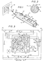
- the pole contacts P1, P2 are cells, and, in the embodiment shown, the earth contact T is a pin.
- the control device 12 comprises connection members P'1, P'2 and T 'specific to its connection to these pole contacts P1, P2 and to this contact of earth T.
- these organs connection P'1, P'2 and T ' are complementary contacts of those P1, P2 and T of the socket outlet 10, and they jointly belong to a sheet 13 suitable for being skewered on the latter.
- connection members P'1, P'2 are therefore pins, and the connection member T 'a cell.
- sheet 13 is not polarized, and therefore includes, from a distance, one of the other, and symmetrically on either side of the alignment connection members P'1, P'2, two connection members T ', figure 2.
- sheet 13 is integral with the housing 14 that includes the control device 12, forming with this housing 14 a one-piece assembly.
- This control device 12 is thus advantageously can be operated with one hand.
- the housing 14 can be, and is indeed, made in one or two pieces, and, for example, in two shells.
- sheet 13 works frontally, in end of housing 14.
- the control device 12 comprises, overall, and in combination, in its housing 14, a phase 15 indicating device, suitable for locating geometrically the phase with respect to the pole contacts P1, P2 of the socket outlet 10, and a test device 16 suitable for sending a fault pulse by orienting systematically this on the connection member P'1, P'2 corresponding to that of these pole contacts P1, P2 which is phase contact, for controlling the capacity of tripping of the placed differential protection device upstream.
- the phase indicating device 15 itself comprises overall, two display means D1, D2, in practical red light-emitting diodes, which, at the rate of one per pole contact P1, P2, and in conjunction with a detection circuit 17 detailed later, are each established respectively in parallel between a coupling 18 specific to a capacitive link with the earth and the two connection members P'1, P'2 corresponding to the two pole contacts P1, P2.
- control device 12 is a single channel device with manual reversal.
- this inverter 20 controls simultaneously two contacts 20A, 20B.
- the contact 20A relates to the connection members P'1, P'2.
- Its central point 21 constitutes, for the whole, a reference point assumed to be at zero potential.
- connection member P'1 or from the connection member P'2 by means of this same contact 20A.
- the corresponding supply voltage is by example of the order of 6.2 V.
- the contact 20B controlled by the inverter 20 concerns the display means D1, D2.
- the light emitting diodes constituting these means display D1, D2 are present on the front on the housing 14.
- the coupling member 18 is a member metallic, such as a plate or a simple foil, which, disposed in the housing 14, and therefore not visible on the figures, counterweight form.
- the circuit detection 17 of the phase indicating device 15 comprises, in series, from the coupling member 18, a bridge divider 22, which is formed, on the one hand, of resistors R3, and, on the other hand, of resistors R4, each time in a desired number, and whose end opposite to the coupling member 18 is connected to the reference point 21, a level detector T1, whose input E1 is connected to the midpoint of the divider bridge 22, and an integrator 25.
- it includes further, downstream of the integrator 25, a logic inverter T2, whose output S2 is connected, via a current limiting resistor R5, at the center point of the contact 20B of the inverter 20.
- the level detector T1 and the logic inverter T2 are constituted by triggers of SCHMITT, for better signal quality.
- the integrator 25 is formed of a network of resistors R6, R7 and of a capacitor C2.
- this integrator 25 is preceded by an orientation diode D3 intended to prevent possible discharge of the capacitor C2 on the low impedance side.
- the test device 16 for its part, comprises, overall, between each of the connection members P'1, P'2 corresponding to the pole contacts P1, P2 and the connection T 'corresponding to earth contact T, a circuit 28, which for the development of a pulse fault D, is controlled by a control member 29 at the available to the user.
- this member 29 is a push button.
- this control member 29 could just as well be a touchpad, not shown.
- control circuit 28 of the device 16 comprises, in series, counting from the command 29, a logic inverter T3, whose input E3 is suppressed by a filter network formed by a capacitor C3 and a resistor R8 mounted in parallel, a monostable control unit M1, which consists of a capacitor C4 and a resistance R9, and which is timed to a value t1 corresponding to the desired duration for the fault pulse D, and, beyond a current limiting resistor R10, a load switch 32, which is interposed between the point 21 and the connection member T ', and which, in practical, consists of a triac.
- this circuit control 28 further comprises between the logic inverter T3 and the control monostable M1, a monostable of M2 lock, which, like the M1 control monostable, is formed of a capacitor C5 and a resistor R11, and which is timed at a value t2 multiple of that t1 at which is timed this monostable command M1.
- the monostable of M2 lock can be timed to a value t2 of the order from 1.8 to 2 s.
- the M1 control monostable is under the control of a logic inverter T4, and, similarly, the monostable M2 locking is under the control of a T5 logic inverter, with, for the desired locking, a feedback loop 36 which, established between the output S5 of the logic inverter T5 and the input E3 of the logic inverter T3, has a diode orientation D5.
- logic inverters T3, T4 and T5 are preferably SCHMITT triggers, for a better signal quality.
- the circuit 28 of the test device 16 further comprises downstream of the load switch 32, a plurality of resistors power R12, R13, R14, R15 ... etc ... arranged in parallel under the control of a range selector 37, which, present on the front of the housing 14, is available to the user.
- a reset link 38 is established between the phase indicating device 15 and the test device 16 thus formed.
- this connection reset 38 occurs between output S2 of the logic inverter T2 of the phase indicating device 15 and the input E4 of the logic inverter T4 of the test device 16, and it includes, in series, a logic inverter T6, a diode orientation D6, and a current limiting resistor R16.
- the T6 logic inverter is preferably constituted by a SCHMITT trigger, for better signal quality.
- connection members P'1, P'2 corresponding to the contacts of pole P1, P2 are connected together, in parallel one by relation to the other, and in parallel towards the device phase indicator 15 and test device 16, to the organ of connection T 'corresponding to the earth contact T, by a link 40, comprising, for checking a good connection to the earth of this earth contact T, in addition to the diodes orientation D7, D8, a display means D10.
- this display means D10 is consisting of a light emitting diode, for example of green color, present on the front of the case 14.
- this light emitting diode is arranged in a triangle with light-emitting diodes constituting the display means D1, D2 each associated respectively to the pole contacts P1, P2.
- connection members P'1, P'2 corresponding the pole contacts P1, P2 are also interconnected, in parallel with the phase indicating device 15 and of the test device 16, by a link 41 comprising, for a check for the presence of a voltage between these contacts pole P1, P2, a display means D12.
- this display means D12 is consisting of a light emitting diode, for example of red color, present on the front of the case 14.
- control device 12 In either case, the operation described below, the control device 12 according to the invention is the same.
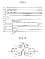
- phase current detected i.e. the current flowing as shown between phase and earth
- the phase current detected is transformed into voltage across the resistors R4 of the bridge divider 22, line L1 in Figure 4.
- the corresponding signal which, in the raw state, is more or less irregular, ensures the excitation of the means of display D1, D2 concerned, after smoothing and inversion by the logic inverter T2, line L4 in Figure 4.
- test device 16 is located temporarily inhibited by the reset link 38.
- control member 29 is a push button
- voltage on input E3 of the inverter logic T3 of the control circuit 28 of the test device 16 suddenly goes from level + to level 0, as indicated in solid line at line L7 in Figure 4.
- this voltage is an alternating voltage, as indicated in broken lines on this line L7 in FIG. 4.
- the voltage at the output S3 of the logic inverter T3 of the control circuit 28 of the device test 16 switches from level 0 to level +, and, by consequence, it is the same for the voltage at input E5 of the logic inverter T5, line L8 in figure 4.
- this charge is sufficient to bring back to level + the voltage at input E4 of the logic inverter T4, line L10 of figure 4, and therefore to bring back to level 0 the voltage at the output S4 of this logic inverter T4, line L11 in Figure 4.
- any possible new intervention on the control member 29 remains ineffective, which avoids repeatedly sending D fault pulses within a period of time too short, and therefore minimizes, on the one hand, a possible potential rise on earth, and, on the other hand, a temperature rise of power resistors R12, R13, R14, R15 ... if the differential protection device upstream is defective.
- the duration of the fault pulse D which, as indicated, corresponds to the value t1 of the time delay of the monostable control M1 is greater than the time limit protection devices not triggered differential called selective, delayed triggering, and at maximum breaking time of protective devices normal differential.
- Time-delayed fuses F1, F2 are time-delayed at one slightly higher value, so as to let this fault pulse D.
- the diagram in FIG. 5 relates to a variant of automatic two-way construction.
- phase 15 indicating device and a testing device 16 for each of the connection members P'1, P'2, and therefore for each of the display means D1, D2.
- these D14 orientation diodes are diodes with very low reverse current, and, such that shown, they are doubled, to reduce the currents corresponding leakage residuals.
- control member 29 there is only one control member 29 for the two test devices 16 in the alternative embodiment shown, with, between this control member 29 and these test devices 16, orientation diodes D15.
- Such an automatic two-way embodiment variant simultaneously scans the two pole contacts P1, P2 of the base socket outlet 10 to be checked.
- bivoie no shown there is provided a coupling member 18, and possibly a control member 29, for each of the connection members P'1, P'2, and therefore for each of the means display D1, D2.
Landscapes
- Engineering & Computer Science (AREA)
- Power Engineering (AREA)
- Testing Of Short-Circuits, Discontinuities, Leakage, Or Incorrect Line Connections (AREA)
- Emergency Protection Circuit Devices (AREA)
- Details Of Connecting Devices For Male And Female Coupling (AREA)
- Cable Accessories (AREA)
Claims (21)
- Prüfgerät für Anschlußstelle mit Erdkontakt und Differentialschutz, umfassend in Verbindung miteinander Anschlußeinrichtungen (P'1, P'2, T'), die zu deren Anklemmen an die Pol- (P1, P2) und Erdkontakte (T) der Steckdose (10) einer derartigen Anschlußstelle geeignet sind, eine Phasenanzeigeeinrichtung (15), die geeignet ist, die Phase bezüglich der Polkontakte (P1, P2) dieser Anschlußstellensteckdose (10) geometrisch zu bestimmen, und umfassend zwei Sichtbarmachungsmittel (D1, D2), im Verhältnis von einem pro Polkontakt (P1, P2) und gesteuert durch eine dem Benutzer zur Verfügung stehende Betätigungseinrichtung (29), eine Versuchsvorrichtung (16), die geeignet ist, einen Fehlerimpuls (D) zu senden, wobei dieser systematisch auf die Anschlußeinrichtung (P'1, P'2) zu gerichtet ist, die demjenigen dieser Polkontakte (P1, P2) entspricht, der der Phasenkontakt ist, für die Prüfung der Auslösefähigkeit der stromaufwärts angeordneten Differentialschutzvorrichtung.
- Prüfgerät nach Anspruch 1, dadurch gekennzeichnet, daß in Verbindung mit einem Detektionsschaltkreis (17) die zwei Sichtbarmachungsmittel (D1, D2) jeweils parallel zwischen einer Kopplungseinrichtung (18), die zu einer kapazitiven Verbindung mit der Erde geeignet ist, und den zwei Anschlußeinrichtungen (P'1, P'2), die den zwei Polkontakten (P1, P2) entsprechen, eingerichtet sind.
- Prüfgerät nach Anspruch 2, dadurch gekennzeichnet, daß der Detektionsschaltkreis (17) der Phasenanzeigevorrichtung (15) in Reihe von der Kopplungseinrichtung (18) ausgehend einen Brückenteiler (22), einen Niveaudetektor (T1), einen Integrator (25) und eventuell einen logischen Inverter (T2) umfaßt.
- Prüfgerät nach einem der Ansprüche 2 oder 3, dadurch gekennzeichnet, daß die Kopplungseinrichtung (18) eine Metalleinrichtung, wie eine Platte ist, die Gegengewichte bildet.
- Prüfgerät nach einem der Ansprüche 1 bis 4, dadurch gekennzeichnet, daß die Versuchsvorrichtung (16) zwischen jeder der Anschlußeinrichtungen (P'1, P'2), die den Polkontakten (P1, P2) entsprechen, und der Anschlußeinrichtung (T'), die dem Erdkontakt (T) entspricht, einen Betätigungsschaltkreis (28) umfaßt, der zur Erzeugung eines Fehlerimpulses (D) durch eine dem Benutzer zur Verfügung stehende Betätigungseinrichtung (29) gesteuert wird.
- Prüfgerät nach Anspruch 5, dadurch gekennzeichnet, daß der Betätigungsschaltkreis (28) der Versuchsvorrichtung (16) in Reihe, von der Betätigungseinrichtung (29) ausgehend, einen logischen Inverter (T3), eine monostabile Betätigungsstufe (M1) und einen Ladeumschalter (32) umfaßt.
- Prüfgerät nach Anspruch 6, dadurch gekennzeichnet, daß der Betätigungsschaltkreis (28) der Versuchsvorrichtung (16) außerdem zwischen dem logischen Inverter (T3) und der monostabilen Betätigungsstufe (M1) eine monostabile Verriegelungsstufe (M2) umfaßt, die mit einem mehrfachen Wert von demjenigen verzögert wird, mit dem die monostabile Betätigungsstufe (M1) verzögert wird.
- Prüfgerät nach einem der Ansprüche 5 oder 6, dadurch gekennzeichnet, daß der Betätigungsschaltkreis (28) der Versuchsvorrichtung (16) außerdem stromabwärts von dem Ladeumschalter (32) eine Vielzahl von Hochbelastungswiderständen (R12, R13, R14, R15...) umfaßt, die parallel unter der Kontrolle eines dem Benutzer zur Verfügung stehenden Bereichsschalters (37) angeordnet sind.
- Prüfgerät nach einem der Ansprüche 5 bis 8, dadurch gekennzeichnet, daß die Betätigungseinrichtung (28) der Versuchsvorrichtung (16) ein Druckknopf ist.
- Prüfgerät nach einem der Ansprüche 5 bis 8, dadurch gekennzeichnet, daß die Betätigungseinrichtung (29) der Versuchsvorrichtung (16) eine Sensortaste ist.
- Prüfgerät nach einem der Ansprüche 1 bis 10, dadurch gekennzeichent, daß eine Nullsetzverbindung (38) zwischen der Phasenanzeigevorrichtung (15) und der Versuchsvorrichtung (16) eingerichtet ist.
- Prüfgerät nach den Ansprüchen 3 und 11 zusammengenommen, dadurch gekennzeichnet, daß die Nullsetzverbindung (38) einen logischen Inverter (T6) umfaßt, der das Laden eines Kondensators (C6) kontrolliert, der zwischen dem Brückenteiler (22) des Detektionsschaltkreises (17) der Phasenanzeigevorrichtung (15) und dem Ausgang dieses Detektionsschaltkreises (17) eingerichtet ist.
- Prüfgerät nach einem der Ansprüche 1 bis 12, dadurch gekennzeichnet, daß es nur eine Phasenanzeigevorrichtung (15) und eine Versuchsvorrichtung (16) für die beiden Anschlußeinrichtungen (P'1, P'2), die den Polkontakten (P1,P2) entsprechen, umfaßt mit einem dem Benutzer zur Verfügung stehenden Inverter (20), der es erlaubt, von dem einen zum anderen umzuschalten.
- Prüfgerät nach einem der Ansprüche 1 bis 12, dadurch gekennzeichnet, daß es eine Phasenanzeigevorrichtung (15) und eine Versuchsvorrichtung (16) für jede der Anschlußeinrichtungen (P'1, P'2), die den Polkontakten (P1,P2) entsprechen, umfaßt.
- Prüfgerät nach den Ansprüchen 2 und 14 zusammengenommen, dadurch gekennzeichnet, daß es eine einzige Kopplungseinrichtung (18) für die zwei Phasenanzeigevorrichtungen (15) mit Richtdioden (D14) zwischen dieser Kopplungseinrichtung (18) und diesen Phasenanzeigevorrichtungen (15) umfaßt.
- Prüfgerät nach den Ansprüchen 5 und 14 zusammengenommen, dadurch gekennzeichnet, daß es eine einzige Betätigungseinrichtung (29) für die zwei Versuchsvorrichtungen (16) mit Richtdioden (D15) zwischen dieser Betätigungseinrichtung (29) und diesen Versuchsvorrichtungen (16) umfaßt.
- Prüfgerät nach einem der Ansprüche 1 bis 16, dadurch gekennzeichnet, daß parallel bezüglich der oder den Phasenanzeigevorrichtungen (15) und der oder den Versuchsvorrichtungen (16) die Anschlußeinrichtungen (P'1, P'2), die den Polkontakten (P1, P2) entsprechen, gemeinsam mit der Anschlußeinrichtung (T'), die dem Erdkontakt (T) entspricht, durch eine Verbindung (40) verbunden sind, die ein Sichtbarmachungsmittel (D10) umfaßt.
- Prüfgerät nach einem der Ansprüche 1 bis 17, dadurch gekennzeichnet, daß parallel bezüglich der oder den Phasenanzeigevorrichtungen (15) und der oder den Versuchsvorrichtungen (16) die Anschlußeinrichtungen (P'1, P'2), die den Polkontakten (P1, P2) entsprechen, untereinander durch eine Verbindung (41) verbunden sind, die ein Sichtbarmachungsmittel (D12) umfaßt.
- Prüfgerät nach einem der Ansprüche 17 oder 18, dadurch gekennzeichnet, daß die Verbindung (40) zwischen diesen Anschlußeinrichtungen (P'1, P'2) und der Anschlußeinrichtung (T'), die dem Erdkontakt (T) entspricht und/oder der Verbindung (41), die sie untereinander verbindet, stromaufwärts zweier verzögerter Sicherungen (F1, F2) eingeschaltet ist, wobei diese Sicherungen (F1, F2) jeweils jeder der Anschlußeinrichtungen (P'1, P'2), die den Polkontakten (P1, P2) entsprechen, zugeordnet sind.
- Prüfgerät nach einem der Ansprüche 1 bis 19, dadurch gekennzeichnet, daß seine Anschlußeinrichtungen (P'1, P'2, T') komplementäre Kontakte zu denen (P1, P2, T) der Steckdose der Anschlußstelle (10) sind und gemeinsam zu einem Stecker (13) gehören, der geeignet ist, an die Letztere gesteckt zu werden.
- Prüfgerät nach Anspruch 20, dadurch gekennzeichnet, daß sein Stecker (13) mit seinem Gehäuse (14) fest verbunden ist, wobei er mit diesem einen einstückigen Aufbau bildet.
Applications Claiming Priority (2)
| Application Number | Priority Date | Filing Date | Title |
|---|---|---|---|
| FR9212906A FR2697343B1 (fr) | 1992-10-23 | 1992-10-23 | Appareil de contrôle pour prise de courant à contact de terre et protection différentielle. |
| FR9212906 | 1992-10-23 |
Publications (2)
| Publication Number | Publication Date |
|---|---|
| EP0597746A1 EP0597746A1 (de) | 1994-05-18 |
| EP0597746B1 true EP0597746B1 (de) | 1998-01-07 |
Family
ID=9434959
Family Applications (1)
| Application Number | Title | Priority Date | Filing Date |
|---|---|---|---|
| EP93402583A Expired - Lifetime EP0597746B1 (de) | 1992-10-23 | 1993-10-21 | Prüfgerät für Steckdose mit Erdung und Differentialschutz |
Country Status (5)
| Country | Link |
|---|---|
| EP (1) | EP0597746B1 (de) |
| AT (1) | ATE161971T1 (de) |
| DE (1) | DE69316164D1 (de) |
| ES (1) | ES2112972T3 (de) |
| FR (1) | FR2697343B1 (de) |
Families Citing this family (5)
| Publication number | Priority date | Publication date | Assignee | Title |
|---|---|---|---|---|
| FR2727761A1 (fr) | 1994-12-01 | 1996-06-07 | Catu Ets | Appareil de controle pour socle de prise de courant a contact de terre |
| US5625285A (en) * | 1995-06-01 | 1997-04-29 | A. W. Sperry Instruments, Inc. | AC power outlet ground integrity and wire test circuit device |
| US6072317A (en) * | 1998-03-27 | 2000-06-06 | Eaton Corporation | Plug-in multifunction tester for AC electrical distribution system |
| FR2851049B1 (fr) * | 2003-02-12 | 2005-04-22 | Electricite De France | Dispositif de controle destine a tester une installation de distribution de courant |
| EP1657556A1 (de) * | 2004-11-11 | 2006-05-17 | ABB PATENT GmbH | Spannungs- und Phasenprüfer |
Family Cites Families (2)
| Publication number | Priority date | Publication date | Assignee | Title |
|---|---|---|---|---|
| US3898557A (en) * | 1973-11-12 | 1975-08-05 | Daltec Systems Inc | Electrical device for testing a ground fault circuit interrupter |
| DE3421829A1 (de) * | 1984-06-13 | 1985-12-19 | Brown, Boveri & Cie Ag, 6800 Mannheim | Messverfahren zur ueberpruefung von schutzmassnahmen in elektrischen anlagen und messgeraet zur durchfuehrung des verfahrens |
-
1992
- 1992-10-23 FR FR9212906A patent/FR2697343B1/fr not_active Expired - Lifetime
-
1993
- 1993-10-21 EP EP93402583A patent/EP0597746B1/de not_active Expired - Lifetime
- 1993-10-21 AT AT93402583T patent/ATE161971T1/de not_active IP Right Cessation
- 1993-10-21 DE DE69316164T patent/DE69316164D1/de not_active Expired - Lifetime
- 1993-10-21 ES ES93402583T patent/ES2112972T3/es not_active Expired - Lifetime
Also Published As
| Publication number | Publication date |
|---|---|
| FR2697343B1 (fr) | 1994-12-30 |
| ATE161971T1 (de) | 1998-01-15 |
| DE69316164D1 (de) | 1998-02-12 |
| ES2112972T3 (es) | 1998-04-16 |
| EP0597746A1 (de) | 1994-05-18 |
| FR2697343A1 (fr) | 1994-04-29 |
Similar Documents
| Publication | Publication Date | Title |
|---|---|---|
| FR2504749A1 (fr) | Dispositif de protection de charge a semi-conducteurs avec une faculte d'essai | |
| FR2480523A1 (fr) | Appareil coupe-circuit a affichage et entree de parametres multiples | |
| EP0240434A1 (de) | Schutzschaltung für eine Zerhackerspeisung | |
| WO2019110711A1 (fr) | Procede de detection de l'etat d'un appareil de protection electrique dans une installation electrique et dispositif de detection mettant en oeuvre ledit procede | |
| EP0597746B1 (de) | Prüfgerät für Steckdose mit Erdung und Differentialschutz | |
| EP0060790B1 (de) | Fehlerstromempfindliche Ausschalter | |
| FR3010848A1 (fr) | Dispositif et procede de securite pour installation electrique | |
| EP1619924B1 (de) | Telefon-Verteilsystem | |
| WO2012146619A1 (fr) | Système de protection et de supervision d'un circuit de distribution d'énergie électrique à courant continu | |
| EP0715172A1 (de) | Testgerät für geerdete Wandsteckdose | |
| EP2648010A1 (de) | Verfahren zur Verwaltung von Alarmsignalen in Abhängigkeit von den Fehlerströmen in einer elektrischen Anlage, und Vorrichtung zur Umsetzung dieses Verfahrens | |
| EP0524300A1 (de) | Vorrichtung zum schutz von elektrischen geräten, maschinen und anlagen | |
| FR3094848A1 (fr) | Procédés et systèmes de protection électrique | |
| EP0337235B1 (de) | Schutzrelais-Prüfanordnung für die Verwendung während des Betriebs des Relais | |
| FR2504747A1 (fr) | Dispositif de protection de charge a semi-conducteurs avec une detection de rupture de phase | |
| FR2538179A1 (fr) | Declencheur differentiel residuel a detection de variation d'etat | |
| EP0320409B1 (de) | Statischer Auslöser mit externer Versorgung | |
| EP4311053A1 (de) | Modul zur erkennung eines elektrischen fehlers für ein elektrisches schutzgerät und entsprechendes verfahren | |
| EP2626881B1 (de) | Elektrisches Sicherheitsverfahren und -vorrichtung für Erdschluss | |
| EP4075471A1 (de) | Elektrisches hilfsschutzmodul, elektrisches schutzgerät mit einem solchen modul und entsprechendes betriebsverfahren | |
| BE1010688A7 (fr) | Interrupteur differentiel. | |
| EP0253709A1 (de) | Überwachungsanlage mit in einer Schleife gespeisten Detektoren | |
| EP0342579A1 (de) | Vorrichtung für den Autonomietest bei Notbeleuchtungsblöcken | |
| EP1213740A1 (de) | Automatische Rückstellvorrichtung für modulares Schutzgerät | |
| FR2832805A1 (fr) | Appareil portable autonome de test pour detecteur de defauts de cables |
Legal Events
| Date | Code | Title | Description |
|---|---|---|---|
| PUAI | Public reference made under article 153(3) epc to a published international application that has entered the european phase |
Free format text: ORIGINAL CODE: 0009012 |
|
| AK | Designated contracting states |
Kind code of ref document: A1 Designated state(s): AT BE CH DE ES GB IE IT LI NL PT SE |
|
| 17P | Request for examination filed |
Effective date: 19940811 |
|
| 17Q | First examination report despatched |
Effective date: 19960718 |
|
| GRAG | Despatch of communication of intention to grant |
Free format text: ORIGINAL CODE: EPIDOS AGRA |
|
| GRAH | Despatch of communication of intention to grant a patent |
Free format text: ORIGINAL CODE: EPIDOS IGRA |
|
| GRAH | Despatch of communication of intention to grant a patent |
Free format text: ORIGINAL CODE: EPIDOS IGRA |
|
| GRAA | (expected) grant |
Free format text: ORIGINAL CODE: 0009210 |
|
| AK | Designated contracting states |
Kind code of ref document: B1 Designated state(s): AT BE CH DE ES GB IE IT LI NL PT SE |
|
| PG25 | Lapsed in a contracting state [announced via postgrant information from national office to epo] |
Ref country code: NL Free format text: LAPSE BECAUSE OF FAILURE TO SUBMIT A TRANSLATION OF THE DESCRIPTION OR TO PAY THE FEE WITHIN THE PRESCRIBED TIME-LIMIT Effective date: 19980107 Ref country code: GB Free format text: LAPSE BECAUSE OF FAILURE TO SUBMIT A TRANSLATION OF THE DESCRIPTION OR TO PAY THE FEE WITHIN THE PRESCRIBED TIME-LIMIT Effective date: 19980107 Ref country code: AT Free format text: LAPSE BECAUSE OF FAILURE TO SUBMIT A TRANSLATION OF THE DESCRIPTION OR TO PAY THE FEE WITHIN THE PRESCRIBED TIME-LIMIT Effective date: 19980107 |
|
| REF | Corresponds to: |
Ref document number: 161971 Country of ref document: AT Date of ref document: 19980115 Kind code of ref document: T |
|
| REG | Reference to a national code |
Ref country code: CH Ref legal event code: EP |
|
| ITF | It: translation for a ep patent filed | ||
| REF | Corresponds to: |
Ref document number: 69316164 Country of ref document: DE Date of ref document: 19980212 |
|
| PG25 | Lapsed in a contracting state [announced via postgrant information from national office to epo] |
Ref country code: SE Free format text: LAPSE BECAUSE OF FAILURE TO SUBMIT A TRANSLATION OF THE DESCRIPTION OR TO PAY THE FEE WITHIN THE PRESCRIBED TIME-LIMIT Effective date: 19980407 Ref country code: PT Free format text: LAPSE BECAUSE OF FAILURE TO SUBMIT A TRANSLATION OF THE DESCRIPTION OR TO PAY THE FEE WITHIN THE PRESCRIBED TIME-LIMIT Effective date: 19980407 |
|
| PG25 | Lapsed in a contracting state [announced via postgrant information from national office to epo] |
Ref country code: DE Free format text: LAPSE BECAUSE OF FAILURE TO SUBMIT A TRANSLATION OF THE DESCRIPTION OR TO PAY THE FEE WITHIN THE PRESCRIBED TIME-LIMIT Effective date: 19980408 |
|
| REG | Reference to a national code |
Ref country code: ES Ref legal event code: FG2A Ref document number: 2112972 Country of ref document: ES Kind code of ref document: T3 |
|
| NLV1 | Nl: lapsed or annulled due to failure to fulfill the requirements of art. 29p and 29m of the patents act | ||
| REG | Reference to a national code |
Ref country code: IE Ref legal event code: FG4D Free format text: 78180 |
|
| GBV | Gb: ep patent (uk) treated as always having been void in accordance with gb section 77(7)/1977 [no translation filed] |
Effective date: 19980107 |
|
| PG25 | Lapsed in a contracting state [announced via postgrant information from national office to epo] |
Ref country code: IE Free format text: LAPSE BECAUSE OF NON-PAYMENT OF DUE FEES Effective date: 19980824 |
|
| REG | Reference to a national code |
Ref country code: IE Ref legal event code: FD4D Ref document number: 78180 Country of ref document: IE |
|
| PG25 | Lapsed in a contracting state [announced via postgrant information from national office to epo] |
Ref country code: LI Free format text: LAPSE BECAUSE OF NON-PAYMENT OF DUE FEES Effective date: 19981031 Ref country code: CH Free format text: LAPSE BECAUSE OF NON-PAYMENT OF DUE FEES Effective date: 19981031 Ref country code: BE Free format text: LAPSE BECAUSE OF NON-PAYMENT OF DUE FEES Effective date: 19981031 |
|
| PLBE | No opposition filed within time limit |
Free format text: ORIGINAL CODE: 0009261 |
|
| STAA | Information on the status of an ep patent application or granted ep patent |
Free format text: STATUS: NO OPPOSITION FILED WITHIN TIME LIMIT |
|
| 26N | No opposition filed | ||
| BERE | Be: lapsed |
Owner name: S.A. DES ETS CATU Effective date: 19981031 |
|
| REG | Reference to a national code |
Ref country code: CH Ref legal event code: PL |
|
| PGFP | Annual fee paid to national office [announced via postgrant information from national office to epo] |
Ref country code: ES Payment date: 20041014 Year of fee payment: 12 |
|
| PG25 | Lapsed in a contracting state [announced via postgrant information from national office to epo] |
Ref country code: IT Free format text: LAPSE BECAUSE OF NON-PAYMENT OF DUE FEES Effective date: 20051021 |
|
| PG25 | Lapsed in a contracting state [announced via postgrant information from national office to epo] |
Ref country code: ES Free format text: LAPSE BECAUSE OF NON-PAYMENT OF DUE FEES Effective date: 20051022 |
|
| REG | Reference to a national code |
Ref country code: ES Ref legal event code: FD2A Effective date: 20051022 |