EP0598182A1 - Dispositif et procédé de distribuer rapidement des quantités minimes de matériaux visqueux - Google Patents
Dispositif et procédé de distribuer rapidement des quantités minimes de matériaux visqueux Download PDFInfo
- Publication number
- EP0598182A1 EP0598182A1 EP93109278A EP93109278A EP0598182A1 EP 0598182 A1 EP0598182 A1 EP 0598182A1 EP 93109278 A EP93109278 A EP 93109278A EP 93109278 A EP93109278 A EP 93109278A EP 0598182 A1 EP0598182 A1 EP 0598182A1
- Authority
- EP
- European Patent Office
- Prior art keywords
- nozzle
- viscous material
- chamber
- diaphragm
- predetermined
- Prior art date
- Legal status (The legal status is an assumption and is not a legal conclusion. Google has not performed a legal analysis and makes no representation as to the accuracy of the status listed.)
- Granted
Links
Images



Classifications
-
- B—PERFORMING OPERATIONS; TRANSPORTING
- B05—SPRAYING OR ATOMISING IN GENERAL; APPLYING FLUENT MATERIALS TO SURFACES, IN GENERAL
- B05C—APPARATUS FOR APPLYING FLUENT MATERIALS TO SURFACES, IN GENERAL
- B05C11/00—Component parts, details or accessories not specifically provided for in groups B05C1/00 - B05C9/00
- B05C11/10—Storage, supply or control of liquid or other fluent material; Recovery of excess liquid or other fluent material
- B05C11/1002—Means for controlling supply, i.e. flow or pressure, of liquid or other fluent material to the applying apparatus, e.g. valves
- B05C11/1034—Means for controlling supply, i.e. flow or pressure, of liquid or other fluent material to the applying apparatus, e.g. valves specially designed for conducting intermittent application of small quantities, e.g. drops, of coating material
-
- B—PERFORMING OPERATIONS; TRANSPORTING
- B05—SPRAYING OR ATOMISING IN GENERAL; APPLYING FLUENT MATERIALS TO SURFACES, IN GENERAL
- B05B—SPRAYING APPARATUS; ATOMISING APPARATUS; NOZZLES
- B05B12/00—Arrangements for controlling delivery; Arrangements for controlling the spray area
- B05B12/08—Arrangements for controlling delivery; Arrangements for controlling the spray area responsive to condition of liquid or other fluent material to be discharged, of ambient medium or of target ; responsive to condition of spray devices or of supply means, e.g. pipes, pumps or their drive means
- B05B12/085—Arrangements for controlling delivery; Arrangements for controlling the spray area responsive to condition of liquid or other fluent material to be discharged, of ambient medium or of target ; responsive to condition of spray devices or of supply means, e.g. pipes, pumps or their drive means responsive to flow or pressure of liquid or other fluent material to be discharged
-
- B—PERFORMING OPERATIONS; TRANSPORTING
- B05—SPRAYING OR ATOMISING IN GENERAL; APPLYING FLUENT MATERIALS TO SURFACES, IN GENERAL
- B05B—SPRAYING APPARATUS; ATOMISING APPARATUS; NOZZLES
- B05B17/00—Apparatus for spraying or atomising liquids or other fluent materials, not covered by the preceding groups
- B05B17/04—Apparatus for spraying or atomising liquids or other fluent materials, not covered by the preceding groups operating with special methods
-
- B—PERFORMING OPERATIONS; TRANSPORTING
- B05—SPRAYING OR ATOMISING IN GENERAL; APPLYING FLUENT MATERIALS TO SURFACES, IN GENERAL
- B05C—APPARATUS FOR APPLYING FLUENT MATERIALS TO SURFACES, IN GENERAL
- B05C5/00—Apparatus in which liquid or other fluent material is projected, poured or allowed to flow on to the surface of the work
- B05C5/001—Apparatus in which liquid or other fluent material is projected, poured or allowed to flow on to the surface of the work incorporating means for heating or cooling the liquid or other fluent material
-
- B—PERFORMING OPERATIONS; TRANSPORTING
- B05—SPRAYING OR ATOMISING IN GENERAL; APPLYING FLUENT MATERIALS TO SURFACES, IN GENERAL
- B05C—APPARATUS FOR APPLYING FLUENT MATERIALS TO SURFACES, IN GENERAL
- B05C5/00—Apparatus in which liquid or other fluent material is projected, poured or allowed to flow on to the surface of the work
- B05C5/02—Apparatus in which liquid or other fluent material is projected, poured or allowed to flow on to the surface of the work the liquid or other fluent material being discharged through an outlet orifice by pressure, e.g. from an outlet device in contact or almost in contact, with the work
- B05C5/0225—Apparatus in which liquid or other fluent material is projected, poured or allowed to flow on to the surface of the work the liquid or other fluent material being discharged through an outlet orifice by pressure, e.g. from an outlet device in contact or almost in contact, with the work characterised by flow controlling means, e.g. valves, located proximate the outlet
-
- B—PERFORMING OPERATIONS; TRANSPORTING
- B23—MACHINE TOOLS; METAL-WORKING NOT OTHERWISE PROVIDED FOR
- B23K—SOLDERING OR UNSOLDERING; WELDING; CLADDING OR PLATING BY SOLDERING OR WELDING; CUTTING BY APPLYING HEAT LOCALLY, e.g. FLAME CUTTING; WORKING BY LASER BEAM
- B23K3/00—Tools, devices or special appurtenances for soldering, e.g. brazing, or unsoldering, not specially adapted for particular methods
- B23K3/06—Solder feeding devices; Solder melting pans
- B23K3/0607—Solder feeding devices
-
- H—ELECTRICITY
- H05—ELECTRIC TECHNIQUES NOT OTHERWISE PROVIDED FOR
- H05K—PRINTED CIRCUITS; CASINGS OR CONSTRUCTIONAL DETAILS OF ELECTRIC APPARATUS; MANUFACTURE OF ASSEMBLAGES OF ELECTRICAL COMPONENTS
- H05K13/00—Apparatus or processes specially adapted for manufacturing or adjusting assemblages of electric components
- H05K13/04—Mounting of components, e.g. of leadless components
- H05K13/046—Surface mounting
- H05K13/0469—Surface mounting by applying a glue or viscous material
-
- H—ELECTRICITY
- H05—ELECTRIC TECHNIQUES NOT OTHERWISE PROVIDED FOR
- H05K—PRINTED CIRCUITS; CASINGS OR CONSTRUCTIONAL DETAILS OF ELECTRIC APPARATUS; MANUFACTURE OF ASSEMBLAGES OF ELECTRICAL COMPONENTS
- H05K3/00—Apparatus or processes for manufacturing printed circuits
- H05K3/30—Assembling printed circuits with electric components, e.g. with resistors
- H05K3/303—Assembling printed circuits with electric components, e.g. with resistors with surface mounted components
- H05K3/305—Affixing by adhesive
-
- B—PERFORMING OPERATIONS; TRANSPORTING
- B23—MACHINE TOOLS; METAL-WORKING NOT OTHERWISE PROVIDED FOR
- B23K—SOLDERING OR UNSOLDERING; WELDING; CLADDING OR PLATING BY SOLDERING OR WELDING; CUTTING BY APPLYING HEAT LOCALLY, e.g. FLAME CUTTING; WORKING BY LASER BEAM
- B23K2101/00—Articles made by soldering, welding or cutting
- B23K2101/36—Electric or electronic devices
- B23K2101/40—Semiconductor devices
-
- H—ELECTRICITY
- H05—ELECTRIC TECHNIQUES NOT OTHERWISE PROVIDED FOR
- H05K—PRINTED CIRCUITS; CASINGS OR CONSTRUCTIONAL DETAILS OF ELECTRIC APPARATUS; MANUFACTURE OF ASSEMBLAGES OF ELECTRICAL COMPONENTS
- H05K2203/00—Indexing scheme relating to apparatus or processes for manufacturing printed circuits covered by H05K3/00
- H05K2203/01—Tools for processing; Objects used during processing
- H05K2203/0104—Tools for processing; Objects used during processing for patterning or coating
- H05K2203/013—Inkjet printing, e.g. for printing insulating material or resist
-
- H—ELECTRICITY
- H05—ELECTRIC TECHNIQUES NOT OTHERWISE PROVIDED FOR
- H05K—PRINTED CIRCUITS; CASINGS OR CONSTRUCTIONAL DETAILS OF ELECTRIC APPARATUS; MANUFACTURE OF ASSEMBLAGES OF ELECTRICAL COMPONENTS
- H05K2203/00—Indexing scheme relating to apparatus or processes for manufacturing printed circuits covered by H05K3/00
- H05K2203/16—Inspection; Monitoring; Aligning
- H05K2203/163—Monitoring a manufacturing process
-
- H—ELECTRICITY
- H05—ELECTRIC TECHNIQUES NOT OTHERWISE PROVIDED FOR
- H05K—PRINTED CIRCUITS; CASINGS OR CONSTRUCTIONAL DETAILS OF ELECTRIC APPARATUS; MANUFACTURE OF ASSEMBLAGES OF ELECTRICAL COMPONENTS
- H05K3/00—Apparatus or processes for manufacturing printed circuits
- H05K3/30—Assembling printed circuits with electric components, e.g. with resistors
- H05K3/32—Assembling printed circuits with electric components, e.g. with resistors electrically connecting electric components or wires to printed circuits
- H05K3/34—Assembling printed circuits with electric components, e.g. with resistors electrically connecting electric components or wires to printed circuits by soldering
- H05K3/3465—Application of solder
- H05K3/3485—Application of solder paste, slurry or powder
-
- H—ELECTRICITY
- H10—SEMICONDUCTOR DEVICES; ELECTRIC SOLID-STATE DEVICES NOT OTHERWISE PROVIDED FOR
- H10W—GENERIC PACKAGES, INTERCONNECTIONS, CONNECTORS OR OTHER CONSTRUCTIONAL DETAILS OF DEVICES COVERED BY CLASS H10
- H10W72/00—Interconnections or connectors in packages
- H10W72/071—Connecting or disconnecting
- H10W72/073—Connecting or disconnecting of die-attach connectors
-
- H—ELECTRICITY
- H10—SEMICONDUCTOR DEVICES; ELECTRIC SOLID-STATE DEVICES NOT OTHERWISE PROVIDED FOR
- H10W—GENERIC PACKAGES, INTERCONNECTIONS, CONNECTORS OR OTHER CONSTRUCTIONAL DETAILS OF DEVICES COVERED BY CLASS H10
- H10W74/00—Encapsulations, e.g. protective coatings
- H10W74/01—Manufacture or treatment
-
- Y—GENERAL TAGGING OF NEW TECHNOLOGICAL DEVELOPMENTS; GENERAL TAGGING OF CROSS-SECTIONAL TECHNOLOGIES SPANNING OVER SEVERAL SECTIONS OF THE IPC; TECHNICAL SUBJECTS COVERED BY FORMER USPC CROSS-REFERENCE ART COLLECTIONS [XRACs] AND DIGESTS
- Y02—TECHNOLOGIES OR APPLICATIONS FOR MITIGATION OR ADAPTATION AGAINST CLIMATE CHANGE
- Y02P—CLIMATE CHANGE MITIGATION TECHNOLOGIES IN THE PRODUCTION OR PROCESSING OF GOODS
- Y02P70/00—Climate change mitigation technologies in the production process for final industrial or consumer products
- Y02P70/50—Manufacturing or production processes characterised by the final manufactured product
Definitions
- the present invention relates to the dispensing of viscous materials, and more particularly, to the rapid dispensing of minute amounts of adhesives in mounting electronic components on circuit boards prior to solder reflow.
- viscous materials i.e those with a viscosity greater than fifty centipoise.
- Such materials include adhesives, solder paste, solder flux, solder mask, grease, oil, encapsulants, potting compounds, inks, silicones, RTV and cyanoacrylates.
- screening, pin transfer and dispensing from a syringe or valve Screening requires a template and is not readily adaptable to changing application patterns. Pin transfer is relatively fast but the tooling is intensive and inflexible. Syringe dispensing is widely used and is accomplished with pneumatic mechanisms or positive displacement valves.
- Syringe dispensers usually place the tip very close to the substrate, i.e. 0.005 inches for a very small dot and 0.060 inches for a large dot.
- the viscous material is pushed out of the tip and contacts the substrate while it is still connected to the tip. If the viscous material fails to contact the substrate, it will not adhere to the substrate and a poorly formed dot will result.
- the contacting with the substrate is called "wetting.” After the viscous material contacts the surface of the substrate, the tip is pulled back and the resulting string is broken to form a dot.
- Prior viscous material dispensers have typically included a reservoir, feedpath, pinch points, gates or check valves, a chamber and an exit port. These can prevent rapid flow of viscous materials. They can also become clogged.
- the present invention provides an apparatus for rapidly dispensing minute quantities of a viscous material through high speed ejection of a jet of the material. It differs from conventional viscous material dispensers which require a string of material to touch the substrate or work piece before the dispensing tip is pulled back to break off the blob of material.
- a first embodiment of our invention includes a reservoir that holds a predetermined volume of a viscous material.
- a chamber communicates with the reservoir for continuously receiving the viscous material therefrom.
- the chamber has a flexible resilient diaphragm which forms an exterior wall thereof.
- An impact mechanism which may comprise a solenoid actuated hammer, applies a predetermined momentum to the diaphragm to propel a predetermined minute quantity of the viscous material from the chamber through a nozzle at a high velocity. This minute quantity takes the form of a very small jet of fluid.
- the sudden decrease of the chamber pressure and the forward momentum of the jet "pinches" the jet to form a droplet, or blob.
- a critical aspect of the invention for many viscous materials is that the chamber is heated to control the viscosity of the material.
- the diaphragm may be made of a synthetic material or it may be made of a thin metal sheet. In the latter case, a resilient compressible bumper such as an O-ring is provided under the metal sheet to rapidly restore the original configuration of the sheet after being struck by the hammer.
- the reservoir is preferably pressurized with gas to force the viscous material into the chamber for the purpose of refilling the chamber. Dispensing rates in excess of four blobs per second can be achieved. Variations in the height of the nozzle from the surface of the workpiece are not critical to uniform rapid dispensing.
- a second embodiment of our invention eliminates the diaphragm and instead rapidly retracts a nozzle relative to a fluid feed conduit to eject very small droplets or blobs of viscous material.
- a strain gauge detects refill of the chamber inside the nozzle and sends a signal to control refill logic circuitry.
- a fiber optic droplet detector is utilized to detect the presence or absence of the jet.
- Fig. 1 is a side elevation view of a first embodiment of our dispensing apparatus with portions vertically sectioned.
- Fig. 2 is a top view of the base of the chamber of the first embodiment illustrated in Fig. 1.
- Figs. 3 and 4 are enlarged vertical sectional views illustrating the operation of the impact mechanism of the first embodiment.
- Fig. 5 is a vertical sectional view of an alternate form of the chamber of the first embodiment.
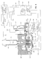
- Fig. 6 is a part vertical sectional view and part diagrammatic view of a second embodiment of our dispensing apparatus.
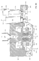
- Fig. 6A is an enlarged view of the fluid feed conduit, nozzle, impact hammer and adjacent structure of the second embodiment.
- Fig. 7-10 are a series of enlarged vertical sectional views of the nozzle and surrounding structure of the second embodiment illustrating the formation and ejection of a droplet and the refill of the nozzle chamber.
- the first embodiment of our apparatus includes a reservoir such as syringe cartridge 10 (Fig. 1) that holds a predetermined volume of a viscous material.
- This cartridge is a standard commercially available item.
- a chamber 12 communicates with the reservoir for continuously receiving the viscous material therefrom.
- the reservoir is pressurized with gas from a source shown diagrammatically at 13 in order to force the fluid into the chamber.
- the chamber is formed of a joined rectangular top cover 14 and a rectangular base 16.
- the cover and base are generally planar and may be machined or molded from suitable plastic material.
- a female threaded hub 18 of the reservoir screws over a threaded male fitting 20 seated in a cylindrical inlet 22 of the cover 14.
- An O-ring 24 provides a seal between fitting 20 and inlet 22.
- the chamber 12 has an elongate horizontal passage 26 (Figs. 1 and 2) formed therein which leads from the cylindrical inlet 22 to a stepped cylindrical chamber portion 28.
- a flexible resilient diaphragm 30 overlies the top of this chamber portion and forms an exterior wall thereof.
- This diaphragm may be made of a synthetic material such as that sold under the trademark VITON.
- the VITON sheet may be 0.032 inches thick.
- the diaphragm is made of a thin metal sheet such as stainless steel sheet having a thickness of 0.001 inches.
- An impact mechanism including a vertically reciprocable hammer 34 actuated by a solenoid 36 applies a predetermined momentum to the diaphragm 30.
- This causes a predetermined minute quantity (jet of fluid) 37 (Fig. 4) of the viscous material to be rapidly ejected from the chamber through a nozzle 38 forming a high speed jet.
- a resilient compressible bumper such as a VITON O-ring 32 is provided under the metal sheet 30 to rapidly restore the original configuration of the sheet after being struck by the lower end of a vertical hammer 34.
- the O-ring has a gap or cut 33 therein (Fig. 2) which is aligned with the passage 26 in the base 16 so that viscous material from the reservoir 10 can re-fill the chamber portion 28.
- the nozzle 38 comprises another rectangular piece of stainless steel that overlies the lower surface of the base 16 and is secured thereto by screws 39, only one of which is visible in Fig. 1.
- the nozzle 38 has an upper conical orifice 38a and a lower cylindrical passage 38b.
- the orifice 38a communicates with the lower end of the stepped cylindrical chamber portion 28.
- the diameter of the cylindrical passage 38b of the nozzle may measure 0.020 inches or less.
- the chamber 12 is preferably heated to control the viscosity of the material dispensed through the nozzle 38. This is accomplished via a heater block 40 (Fig. 1) which is secured to nozzle 38 via screws 42, only one of which is visible in Fig. 1.
- a resistor 44 and a thermocouple 46 are mounted in correspondingly sized holes which are bored in the heater block 40.
- the resistor and thermocouple are connected to a controller shown diagrammatically at 48 in Fig. 1.
- the thermocouple generates a feedback signal representative of the temperature of the heater block and continuously adjusts the level of a heat energizing signal applied to the resistor in order to maintain the heater block, and thus the chamber portion 28 and nozzle 38 at a preselected constant temperature above ambient temperature.
- the thermocouple 46 (Fig. 1) is preferably a J-type thermocouple having a pair of Iron and Constantan wires which are physically joined at a sensing junction. The wires are supported in spaced apart, parallel relation inside a cable (not illustrated) which connects the thermocouple junction to the controller 48.
- the thermocouple junction is in physical contact with the heater block 40 and generates a feedback signal whose current is proportional to the temperature of the block.
- the resistor 44 may be a standard resistor having a value of, for example, one hundred ohms. The resistor generates heat in proportion to the power of the energizing signal applied thereto.
- the end terminals of the resistor (not illustrated) are connected via a cable (not illustrated) to the controller 48.
- the controller 48 provides a proportional integral differential (PID) control.
- PID proportional integral differential
- the controller supplies electric current to the resistor 44 in the heater block 40.
- the controller 48 reads the temperature from the J-type thermocouple 46 and turns the current to the resistor 44 ON and OFF to maintain a constant temperature in the block 40.
- a microprocessor in the controller uses a set of response constants for the mass and heat transfer properties of the block 40 in order to control heating time using PID control equations.
- a constant transfer of heat to the chamber 12 and nozzle 38 from the heater block 40 maintains a constant temperature in the viscous material passing through the nozzle upon energization of the dispensing valve solenoid actuated hammer. The temperature, and thus the viscosity of the viscous fluid is maintained substantially constant despite variations in the rate of delivery through the nozzle.
- the CN9000 is a microprocessor based temperature controller, with a user interface which enables set-up by an operator. Selection of operational controls is made through three keys on a front panel. After parameters have been set, they are locked in by removing a jumper located under a front bezel. The operator may select a control mode and a parameter display resolution. The operator may also utilize a ranging feature of the instrument which limits the range in which a set point may be chosen, or lock out the operator from changing the set point.
- the second set point and output of the CN9000 controller may have proportional or ON/OFF control, and the set point is set as a deviation from the primary set point. Cycle time, proportion band and ON/OFF deadband are set independently of the primary set point.
- the hammer 34 (Fig. 1) slides inside of a hollow guide sleeve 50 whose lower end is secured in the vertical bore of an L-shaped mounting bracket 52.
- a horizontal leg 52a of the mounting bracket is secured to the top of cover 14 of the chamber so that the lower end of the hammer 34 can slide through a hole 54 in the cover to strike the diaphragm 30.
- the solenoid 36 includes a cylindrical armature 56 mounted to the upper end of the hammer 34.
- the solenoid further includes a voice coil assembly 58 through which the armature reciprocates.
- the voice coil assembly is mounted to a vertical leg 52b of the mounting bracket via bolts 60.
- the hammer is biased by a spring 61 towards a raised position illustrated in Figs. 1 and 3.
- An impact actuator circuit shown diagrammatically at 62 is used to apply an impact energizing signal to the solenoid coil 58 to cause the armature 56 to rapidly move downwardly against the bias of the spring 61. This causes the rounded lower end of the hammer 34 to strike the diaphragm 30 as shown in Fig. 4.
- a stop 64 screws around the outside of the upper end of the guide sleeve 50 and may be rotated to adjust the transfer of momentum, i.e., the depth of the impact of the hammer 34 against the diaphragm. The depth of hammer impact controls the size (volume) of the droplet 37 which is ejected from the chamber.
- Dispensing rates in excess of four blobs per second can be achieved with the apparatus just described. Variations in the height of the nozzle from the surface of the workpiece are not critical to uniform rapid dispensing.
- the droplet 37 is formed without the need of having the viscous material first touch the surface of the workpiece before being lifted away. Consistent, uniform sets of viscous material may be deposited with the preferred embodiment.
- Fig. 5 illustrates an alternate form of the first embodiment without the O-ring 32.
- the diaphragm 30 supplies the resilient force to restore its own planar configuration.
- Figs. 6 and 6A illustrate a second embodiment of our dispensing apparatus which does not use a flexible diaphragm. Instead, in the second embodiment a nozzle 70 is rapidly retracted upwardly relative to a fluid feed conduit 72 in order to eject very small droplets or blobs of viscous material at a high velocity from a drop generation chamber 74 inside the nozzle.
- the nozzle 70 and the fluid feed conduit 72 are both generally cylindrical.
- the inner diameter of the drop generation chamber 74 is slightly larger than the outer diameter of the fluid feed conduit 72 so that the former can reciprocate relative to the latter.
- An elastomeric cylindrical sealing gasket 76 which surrounds the lower portion of the fluid feed conduit 72 forms a seal between conduit 72 and nozzle 70, while allowing relative reciprocating motion between them.
- the enlarged upper portion of the fluid feed conduit 72 has a chamber 80 which communicates with the drop generation chamber 74 through a narrow feed passage 82.
- a conventional dispensing syringe 84 has its lower end screwed into the enlarged upper end of the feed conduit 72 so that the interior of the syringe communicates with the chamber 80.
- a plunger 86 within the syringe 84 is driven by air delivered via line 88 from a pressurized air reservoir 90. Pressurized air is selectively metered to the syringe 84 via actuation of a solenoid valve 92 connected to a refill control logic circuit 94 via line 96.
- the enlarged upper end of the fluid feed conduit 72 is mounted in a hole formed in a frame member 98.
- the nozzle 70 has an upper radial flange 100.
- the underside of the flange 100 is normally supported by a plurality of cantilever beams 102.
- the enlarged outer ends of these beams 102 are connected to the frame member 98.
- the inner ends of the cantilever beams 102 have upwardly directed triangular shaped projections, the apexes of which contact the underside of the flange 100.
- An impact hammer 104 has a first end 106 pivotally mounted to the frame member 98 by a pivot assembly 108.
- the impact hammer 104 has a hole 110 through which the lower end of the nozzle 70 projects.
- a solenoid 112 is mounted in a hole in the frame member 98 so that its rod 114 an be connected to a second end 116 of the impact hammer 104 via pin 118.
- the solenoid 112 is connected to a controller circuit 120 via line 122.
- the controller 120 can energize the solenoid 112 to pull its rod 114 upwardly. This pivots the impact hammer 104 upwardly in an amount sufficient so that the portions of the hammer surrounding the hole 110 impact the shoulder 70a of the nozzle. This in turn causes the nozzle to suddenly move upward a slight amount, compressing the elastomeric sealing gasket 76.
- the distal end 116a of the impact hammer rests on a ledge 98a of the frame member when the solenoid 112 is de-energized to permit the impact hammer to swing downwardly under gravitational force and the restoring force of the sealing gasket 76 and the return spring in the solenoid.
- a stroke adjustment micrometer screw assembly 124 is mounted in another hole in the frame member 98 adjacent the solenoid 112.
- the micrometer screw assembly 124 is driven by a stroke adjustment motor 126.
- the stroke adjustment motor is also driven by the controller circuit 120 via line 128.
- the controller circuit 120 can energize the motor 126 to drive the micrometer screw assembly 124 to extend or retract its stop rod 130. This provides an adjustable upper limit for the movement of the impact hammer 104.
- the nozzle 70 is in contact with a surrounding heater ring 132.
- a heating resistor 134 and a thermocouple or thermistor 136 are mounted in holes in the heating ring 132.
- the resistor 134 and thermistor 136 are connected to a nozzle temperature controller circuit 138 via lines 140 and 142.
- the nozzle temperature controller circuit 138 precisely regulates the temperature of the nozzle 70 to achieve a predetermined viscosity of the fluid contained within the drop generation chamber 74. This is accomplished by sending the desired amount of current to the heating resistor 134 utilizing feedback control based upon the output signals from the thermocouple 136. Precise regulation of the temperature of the viscous fluid within the drop generation chamber 74 is extremely critical to high speed uniform ejection of droplets of the viscous material.
- a strain gauge 144 is connected via line 146 to a strain gauge amplifier 148 which also forms part of the controller circuit 120.
- a strain gauge amplifier 148 which also forms part of the controller circuit 120.
- the second embodiment also includes a drop detector in the form of a fiber optic emitter 152 and a detector 154. These components are mounted to the underside of the impact hammer 154 so that the beam from the emitter 152 traverses the hole 110 and is received by the detector 154. The emitter and detector are positioned so that the beam from the emitter is aligned with the exit orifice 78 in the nozzle 70. The emitter and the detector are connected via leads (not illustrated) to the controller 120. Each time a blob or droplet of viscous material is ejected from the nozzle 70, it intercepts the beam from the emitter 152. The detector 154 then sends a signal to the controller 120 via a fiberoptic electronics circuit 155.
- Figs. 7-10 are a series of enlarged vertical sectional views of the nozzle and surrounding structure of the second embodiment illustrating the formation and ejection of a droplet and the refill of the nozzle chamber.
- Chamber 80 inside the upper portion of the nozzle 70 is full of viscous fluid 156.
- the feed passage 82 is filled with viscous fluid 158.
- the drop generation chamber 74 and the exit orifice 78 in the lower portion of the nozzle 70 are filled with viscous fluid 160.
- Solenoid 112 is energized by the controller circuit 120. This rapidly pulls the solenoid rod 114 upwardly, pivoting the impact hammer 104 against the shoulder 70a of the nozzle as illustrated in Fig. 7.
- the solenoid 112 is de-energized.
- the expansive force of the sealing gasket 76, the force of the restoring spring in the solenoid 112 and gravitational force cause the impact hammer 104 to rapidly return to its horizontal position illustrated in Fig. 9.
- the expansion of the sealing gasket 76, along with gravitational force causes the nozzle 100 to descend to its position illustrated in Fig. 9.
- the radial flange 100 of the gasket comes to rest on the apexes of the cantilever beams 102.
- the nozzle 70 descends, the lower end of the fluid feed conduit 72 is withdrawn from the drop generation chamber 74. Air is sucked into the exit orifice 78 and into the drop generation chamber 74 creating a void 164.
- the volume of air taken into the nozzle 70 corresponds to the volume of viscous fluid previously ejected plus the amount of viscous fluid that has flowed back through the feed passage 82 into the chamber 80 inside the upper end of the fluid feed conduit 72.
- the refill control logic circuitry 94 sends a signal via line 96 to open solenoid valve 92.
- This permits pressurized air from the air reservoir 90 to pass via line 88 into the syringe 84.
- Plunger 86 is forced down against the viscous material inside the fluid reservoir 150. Viscous material from the syringe is thus driven into the chamber 80 inside the upper end of the fluid feed conduit 72, through the feed passage 82 and into the drop generation chamber 74. The drop generation chamber is thus refilled.
- the strain gauge 144 detects the pressure rise that occurs when the viscous fluid has refilled the drop generation chamber 74. A signal from the strain gauge 144 is sent via line 146 to the strain gauge amplifier 148.
- the amplified signal from the strain gauge amplifier is sent to the refill control logic circuit 94 which de-energizes the solenoid valve 92 to shut off the pressurized air from the air reservoir 90.
- the detector 154 detects viscous fluid coming out of the nozzle 70 and leaving it as it breaks away to form droplet 162'. Signals from the detector 154 can be used to correct dispensing defects created by incorrect drop ejection that can occur due to the presence of air bubbles in the fluid.
- the impact actuator circuit could provide an impact energizing signal to the voice coil having a specific duration and profile that will optimize ejection of viscous material from the chamber, through the nozzle.
- the chamber and/or nozzle could be subjected to sonic vibrations to facilitate ejection of the viscous material. Therefore, the protection afforded our invention should only be limited in accordance with the scope of the following claims.
Landscapes
- Engineering & Computer Science (AREA)
- Manufacturing & Machinery (AREA)
- Microelectronics & Electronic Packaging (AREA)
- Mechanical Engineering (AREA)
- Coating Apparatus (AREA)
- Feeding, Discharge, Calcimining, Fusing, And Gas-Generation Devices (AREA)
- Application Of Or Painting With Fluid Materials (AREA)
- Spray Control Apparatus (AREA)
- Electric Connection Of Electric Components To Printed Circuits (AREA)
Applications Claiming Priority (2)
| Application Number | Priority Date | Filing Date | Title |
|---|---|---|---|
| US978783 | 1992-11-19 | ||
| US07/978,783 US5320250A (en) | 1991-12-02 | 1992-11-19 | Method for rapid dispensing of minute quantities of viscous material |
Publications (2)
| Publication Number | Publication Date |
|---|---|
| EP0598182A1 true EP0598182A1 (fr) | 1994-05-25 |
| EP0598182B1 EP0598182B1 (fr) | 1997-02-12 |
Family
ID=25526383
Family Applications (1)
| Application Number | Title | Priority Date | Filing Date |
|---|---|---|---|
| EP93109278A Expired - Lifetime EP0598182B1 (fr) | 1992-11-19 | 1993-06-09 | Dispositif et procédé de distribuer rapidement des quantités minimes de matériaux visqueux |
Country Status (5)
| Country | Link |
|---|---|
| US (4) | US5320250A (fr) |
| EP (1) | EP0598182B1 (fr) |
| JP (1) | JPH0768203A (fr) |
| AT (1) | ATE148978T1 (fr) |
| DE (1) | DE69308103T2 (fr) |
Cited By (15)
| Publication number | Priority date | Publication date | Assignee | Title |
|---|---|---|---|---|
| EP0868958A1 (fr) * | 1997-04-04 | 1998-10-07 | Proner Comatel | Procédé de fabrication en continu d'une bande métallique à brasure incorporée, bande obtenue par ce procédé, et pièce de contact découpée dans cette bande |
| WO1998036864A3 (fr) * | 1997-02-21 | 1998-12-03 | Mpm Corp | Systeme de soudage par jet a haute vitesse |
| WO1999004923A1 (fr) * | 1997-07-25 | 1999-02-04 | FREISTAAT BAYERN, vertreten durch die FRIEDRICH-ALEXANDER-UNIVERSITÄT ERLANGEN-NÜRNBERG, DS. vert. durch den REKTOR PROF. DR. JASPER | Distributeur de substance |
| WO1999024211A1 (fr) * | 1997-11-07 | 1999-05-20 | Speedline Technologies, Inc. | Procede et appareil a deposer des matieres sur un substrat |
| EP1029626A3 (fr) * | 1995-11-16 | 2000-10-18 | Nordson Corporation | Procédé et dispositif permettant de distribuer de petites quantités de matière liquide |
| US6324973B2 (en) | 1997-11-07 | 2001-12-04 | Speedline Technologies, Inc. | Method and apparatus for dispensing material in a printer |
| US6453810B1 (en) | 1997-11-07 | 2002-09-24 | Speedline Technologies, Inc. | Method and apparatus for dispensing material in a printer |
| EP0910125A4 (fr) * | 1997-02-04 | 2005-03-09 | Matsushita Electric Industrial Co Ltd | Procede et dispositif pour le scellement d'une puce de circuit integre |
| WO2008151804A1 (fr) * | 2007-06-13 | 2008-12-18 | Marco Systemanalyse Und Entwicklung Gmbh | Dispositif de dosage |
| US9233388B2 (en) | 2009-12-08 | 2016-01-12 | Nordson Corporation | Force amplifying driver system and jetting dispenser and method of dispensing fluid |
| US9346075B2 (en) | 2011-08-26 | 2016-05-24 | Nordson Corporation | Modular jetting devices |
| CN111954459A (zh) * | 2020-09-08 | 2020-11-17 | 陈圆圆 | 一种集成电路加工贴片装置 |
| US11826956B2 (en) | 2019-10-04 | 2023-11-28 | Kana Holdings, LLC | System and method for providing three-dimensional features on large format print products |
| WO2024156687A1 (fr) * | 2023-01-25 | 2024-08-02 | droptical GmbH | Dispositif de génération d'au moins une goutte d'un liquide |
| US12595787B2 (en) | 2022-09-20 | 2026-04-07 | Protec Co., Ltd. | Diaphragm pump |
Families Citing this family (220)
| Publication number | Priority date | Publication date | Assignee | Title |
|---|---|---|---|---|
| US5320250A (en) * | 1991-12-02 | 1994-06-14 | Asymptotic Technologies, Inc. | Method for rapid dispensing of minute quantities of viscous material |
| US6245189B1 (en) * | 1994-12-05 | 2001-06-12 | Nordson Corporation | High Throughput plasma treatment system |
| JP3241251B2 (ja) * | 1994-12-16 | 2001-12-25 | キヤノン株式会社 | 電子放出素子の製造方法及び電子源基板の製造方法 |
| US6186192B1 (en) * | 1995-09-25 | 2001-02-13 | Rapid Analysis And Development Company | Jet soldering system and method |
| US5894980A (en) * | 1995-09-25 | 1999-04-20 | Rapid Analysis Development Comapny | Jet soldering system and method |
| US6276589B1 (en) | 1995-09-25 | 2001-08-21 | Speedline Technologies, Inc. | Jet soldering system and method |
| US5894985A (en) * | 1995-09-25 | 1999-04-20 | Rapid Analysis Development Company | Jet soldering system and method |
| US5868305A (en) * | 1995-09-25 | 1999-02-09 | Mpm Corporation | Jet soldering system and method |
| US5938102A (en) * | 1995-09-25 | 1999-08-17 | Muntz; Eric Phillip | High speed jet soldering system |
| EP0854759B1 (fr) * | 1995-10-13 | 2004-01-28 | Nordson Corporation | Systeme et procede de depot de matiere visqueuse sous une puce a bosses |
| US5747102A (en) * | 1995-11-16 | 1998-05-05 | Nordson Corporation | Method and apparatus for dispensing small amounts of liquid material |
| US6253957B1 (en) | 1995-11-16 | 2001-07-03 | Nordson Corporation | Method and apparatus for dispensing small amounts of liquid material |
| US6267266B1 (en) | 1995-11-16 | 2001-07-31 | Nordson Corporation | Non-contact liquid material dispenser having a bellows valve assembly and method for ejecting liquid material onto a substrate |
| JP3753767B2 (ja) * | 1995-12-21 | 2006-03-08 | 富士写真フイルム株式会社 | 画像形成装置 |
| JP3516284B2 (ja) * | 1995-12-21 | 2004-04-05 | 富士写真フイルム株式会社 | 液体噴射装置 |
| US5699934A (en) * | 1996-01-29 | 1997-12-23 | Universal Instruments Corporation | Dispenser and method for dispensing viscous fluids |
| JP3697315B2 (ja) * | 1996-05-13 | 2005-09-21 | 松下電器産業株式会社 | 接着剤塗布装置 |
| US5916524A (en) | 1997-07-23 | 1999-06-29 | Bio-Dot, Inc. | Dispensing apparatus having improved dynamic range |
| AU4084797A (en) * | 1996-08-27 | 1998-03-19 | Volk Enterprises Inc. | Adhesive seal for timer flange |
| JP3587627B2 (ja) * | 1996-09-05 | 2004-11-10 | 松下電器産業株式会社 | 接着剤塗布方法 |
| DE19641151A1 (de) | 1996-10-07 | 1998-04-09 | Focke & Co | Weichbecher-Verpackung sowie Verfahren und Vorrichtung zum Herstellen derselben und anderer Verpackungen |
| US6112588A (en) * | 1996-10-25 | 2000-09-05 | Speedline Technologies, Inc. | Method and apparatus for measuring the size of drops of a viscous material dispensed from a dispensing system |
| US6412328B1 (en) | 1996-10-25 | 2002-07-02 | Speedline Technologies, Inc. | Method and apparatus for measuring the size of drops of a viscous material dispensed from a dispensing system |
| US5837892A (en) * | 1996-10-25 | 1998-11-17 | Camelot Systems, Inc. | Method and apparatus for measuring the size of drops of a viscous material dispensed from a dispensing system |
| US5855323A (en) * | 1996-11-13 | 1999-01-05 | Sandia Corporation | Method and apparatus for jetting, manufacturing and attaching uniform solder balls |
| US6132809A (en) * | 1997-01-16 | 2000-10-17 | Precision Valve & Automation, Inc. | Conformal coating using multiple applications |
| US5820772A (en) * | 1997-01-21 | 1998-10-13 | Ford Motor Company | Valveless diaphragm pump for dispensing molten metal |
| US5918648A (en) * | 1997-02-21 | 1999-07-06 | Speedline Techologies, Inc. | Method and apparatus for measuring volume |
| US6093251A (en) * | 1997-02-21 | 2000-07-25 | Speedline Technologies, Inc. | Apparatus for measuring the height of a substrate in a dispensing system |
| JP3352385B2 (ja) | 1997-03-21 | 2002-12-03 | キヤノン株式会社 | 電子源基板およびそれを用いた電子装置の製造方法 |
| US5927851A (en) * | 1997-04-07 | 1999-07-27 | Raytheon Company | Vibrating dispenser and method for dispensing filled epoxy adhesives |
| US6283461B1 (en) * | 1997-06-20 | 2001-09-04 | Ceramatec, Inc. | Automatic cyclic fluid delivery device and associated process |
| US6085943A (en) * | 1997-06-30 | 2000-07-11 | Speedline Technologies, Inc. | Controllable liquid dispensing device |
| US5957343A (en) * | 1997-06-30 | 1999-09-28 | Speedline Technologies, Inc. | Controllable liquid dispensing device |
| US5915591A (en) * | 1997-09-10 | 1999-06-29 | Illinois Tool Works Inc. | Electric solenoid valve for hot melt adhesive and method therefor |
| US6022583A (en) * | 1997-12-16 | 2000-02-08 | Nordson Corporation | Method of encapsulating a wire bonded die |
| US7470547B2 (en) * | 2003-07-31 | 2008-12-30 | Biodot, Inc. | Methods and systems for dispensing sub-microfluidic drops |
| JP3329725B2 (ja) * | 1998-03-18 | 2002-09-30 | 富士写真フイルム株式会社 | 液体噴射装置 |
| MXPA01000235A (es) * | 1998-08-24 | 2002-04-24 | Loctite Corp | Sistema distribuidor de fluidos de un solo impulso. |
| DE19840992A1 (de) * | 1998-09-08 | 2000-03-09 | Disetronic Licensing Ag | Drucküberwachung eines bei einer Infusion oder Injektion dosiert zu verabreichenden Produktfluids |
| WO2000023712A1 (fr) | 1998-10-16 | 2000-04-27 | Micro Robotics Systems, Inc. | Appareil de distribution |
| US6475282B1 (en) * | 1999-01-08 | 2002-11-05 | Fastar, Ltd. | Intelligent control system for extrusion head dispensement |
| US6577912B1 (en) * | 1999-01-13 | 2003-06-10 | Matsushita Electric Industrial Co., Ltd | Computer device for production equipment |
| IL128283A0 (en) * | 1999-01-28 | 1999-11-30 | Neo Stitch Ltd | Sewing apparatus |
| US6518996B1 (en) * | 1999-02-22 | 2003-02-11 | Optical Gaging Products, Inc. | Compact video inspection apparatus with Y, Z, X compounded measurement axes |
| US20020014688A1 (en) * | 1999-03-03 | 2002-02-07 | Suresh Ramalingam | Controlled collapse chip connection (c4) integrated circuit package which has two dissimilar underfill materials |
| SE9901253D0 (sv) * | 1999-04-08 | 1999-04-08 | Mydata Automation Ab | Dispensing assembly |
| US6499629B1 (en) * | 1999-05-28 | 2002-12-31 | Nordson Corporation | Dispensing apparatus for viscous liquids |
| DE19931113A1 (de) * | 1999-07-06 | 2001-01-25 | Ekra Eduard Kraft Gmbh | Verfahren zum Aufbringen von Verbindungsmaterialien für eine Verbindung zwischen einem Mikrochip und einem Substrat, Verfahren zum Herstellen einer elektrischen und mechanischen Verbindung zwischen einem Mikrochip und einem Substrat sowie Verwendung eines nach dem Tintendruckprinzip arbeitenden Druckkopfes |
| US6238613B1 (en) | 1999-07-14 | 2001-05-29 | Stratasys, Inc. | Apparatus and method for thermoplastic extrusion |
| US6379464B1 (en) * | 1999-07-30 | 2002-04-30 | K-G Devices Corporation | Apparatus for applying material to a target in relative motion to a dispenser |
| US6478547B1 (en) * | 1999-10-18 | 2002-11-12 | Integrated Designs L.P. | Method and apparatus for dispensing fluids |
| US6541063B1 (en) | 1999-11-04 | 2003-04-01 | Speedline Technologies, Inc. | Calibration of a dispensing system |
| US6605315B1 (en) * | 1999-11-05 | 2003-08-12 | Matsushita Electric Industrial Co., Ltd. | Bonding paste applicator and method of using it |
| FR2800997B1 (fr) * | 1999-11-12 | 2002-02-15 | Valois Sa | Pompe a cadence rapide |
| US6578596B1 (en) | 2000-04-18 | 2003-06-17 | Stratasys, Inc. | Apparatus and method for thermoplastic extrusion |
| WO2001089713A1 (fr) * | 2000-05-25 | 2001-11-29 | Burleigh Automation, Inc. | Systeme de distribution et de visualisation d'adhesif pour systeme d'assemblage automatique |
| EP1161880A1 (fr) * | 2000-06-09 | 2001-12-12 | Brains in motion N.V. | Procédé et dispositif d'application d'une matière visqueuse sur la surface d'un objet |
| SE518640C2 (sv) * | 2000-07-11 | 2002-11-05 | Mydata Automation Ab | Förfarande, anordning för applicering av ett visköst medium på ett substrat, anordning för applicering av ytterligare visköst medium samt användningen av screentryckning |
| SE518642C2 (sv) * | 2000-07-11 | 2002-11-05 | Mydata Automation Ab | Förfarande, anordning för att förse ett substrat med visköst medium, anordning för korrigering av applikationsfel samt användningen av utskjutnings- organ för korrigering av appliceringsfel |
| EP1417035A2 (fr) * | 2000-07-19 | 2004-05-12 | Lenteq Europe B.V. | Systeme permettant de distribuer des portions de substances diverses |
| JP2002072767A (ja) * | 2000-08-25 | 2002-03-12 | Fuji Denki Gazo Device Kk | 円筒状電子写真感光体の製造方法及びその感光体開口端部の接着剤の検出方法 |
| JP2002096013A (ja) * | 2000-09-26 | 2002-04-02 | Fujitsu Ltd | 樹脂塗布方法 |
| JP4502496B2 (ja) * | 2000-11-16 | 2010-07-14 | 富士通株式会社 | Bga実装時におけるはんだ形状評価方法及びbga実装時におけるはんだ形状評価装置及びbga実装時におけるはんだ形状評価プログラムを収納したコンピュータ読み取り可能な記録媒体 |
| JP3742000B2 (ja) * | 2000-11-30 | 2006-02-01 | 富士通株式会社 | プレス装置 |
| FR2817618B1 (fr) * | 2000-12-04 | 2003-03-07 | Renault | Procede et dispositif pour le depot d'un cordon de matiere sur des pieces |
| US6513897B2 (en) | 2000-12-29 | 2003-02-04 | 3M Innovative Properties Co. | Multiple resolution fluid applicator and method |
| JP2002239435A (ja) * | 2001-02-16 | 2002-08-27 | Matsushita Electric Ind Co Ltd | 粘性材料塗布装置、及び粘性材料塗布方法 |
| US6689219B2 (en) | 2001-03-15 | 2004-02-10 | Michael Antoine Birmingham | Apparatus and method for dispensing viscous liquid material |
| TW483792B (en) * | 2001-03-21 | 2002-04-21 | Hannstar Display Corp | Stroke and pressure adjusting device for welding operation in soldering machine |
| US7244310B2 (en) * | 2001-06-01 | 2007-07-17 | Litrex Corporation | Over-clocking in a microdeposition control system to improve resolution |
| US20050016451A1 (en) * | 2001-06-01 | 2005-01-27 | Edwards Charles O. | Interchangeable microdesition head apparatus and method |
| WO2002099849A2 (fr) * | 2001-06-01 | 2002-12-12 | Litrex Corporation | Appareil de microdeposition de materiaux liquides multiples |
| US20040231594A1 (en) * | 2001-06-01 | 2004-11-25 | Edwards Charles O. | Microdeposition apparatus |
| US7449070B2 (en) * | 2001-06-01 | 2008-11-11 | Ulvac, Inc. | Waveform generator for microdeposition control system |
| US6620246B2 (en) | 2001-06-14 | 2003-09-16 | Nylok Corporation | Process controller for coating fasteners |
| US20030059520A1 (en) * | 2001-09-27 | 2003-03-27 | Yung-Ming Chen | Apparatus for regulating temperature of a composition and a method of coating implantable devices |
| US6857543B2 (en) * | 2001-12-01 | 2005-02-22 | Shipley Company, L.L.C. | Low volume dispense unit and method of using |
| US6463879B1 (en) * | 2001-12-07 | 2002-10-15 | Jan A. Czekajewski | Ingestion monitoring system |
| US6711466B2 (en) * | 2002-01-07 | 2004-03-23 | International Business Machines Corporation | Method and system for maintaining a desired distance between a dispenser and a surface |
| US6913182B2 (en) | 2002-01-18 | 2005-07-05 | Precision Dispensing Equipment, Inc. | Method and apparatus for controlled application of flux |
| KR100761235B1 (ko) * | 2002-01-22 | 2007-10-04 | 노드슨 코포레이션 | 액체 스프레이 패턴 검출을 위한 방법 및 장치 |
| US20080172026A1 (en) | 2006-10-17 | 2008-07-17 | Blomquist Michael L | Insulin pump having a suspension bolus |
| EP1340974B1 (fr) * | 2002-03-01 | 2008-09-17 | VMT Bildverarbeitungssysteme GmbH | Procédé de contrôle de qualité de l'application d'un milieu sur un objet |
| NL1020312C2 (nl) * | 2002-04-05 | 2003-10-07 | Otb Groep B V | Werkwijze en inrichting voor het vervaardigen van een display, zoals bijvoorbeeld een polymere OLED display, een display en een substraat ten gebruike bij de werkwijze. |
| US6991825B2 (en) * | 2002-05-10 | 2006-01-31 | Asm Assembly Automation Ltd. | Dispensation of controlled quantities of material onto a substrate |
| US20040173144A1 (en) * | 2002-05-31 | 2004-09-09 | Edwards Charles O. | Formation of printed circuit board structures using piezo microdeposition |
| AU2003249687A1 (en) * | 2002-06-04 | 2003-12-19 | Matrix Technologies Corporation | Liquid transfer device |
| US20040023439A1 (en) * | 2002-07-03 | 2004-02-05 | Kazunari Kimino | Apparatus and method for manufacturing semiconductor device |
| JP4137725B2 (ja) * | 2002-07-10 | 2008-08-20 | 松下電器産業株式会社 | 接合部材の加工寸法決定方法および装置 |
| SE0202247D0 (sv) * | 2002-07-18 | 2002-07-18 | Mydata Automation Ab | Jetting device and method at a jetting device |
| US20040148763A1 (en) * | 2002-12-11 | 2004-08-05 | Peacock David S. | Dispensing system and method |
| USD493672S1 (en) * | 2003-01-31 | 2004-08-03 | Dart Industries Inc. | Serving bowl |
| JP2006519699A (ja) * | 2003-03-06 | 2006-08-31 | デンツプライ インターナショナル インコーポレーテッド | 分配及び混合用チップ |
| US20040186621A1 (en) * | 2003-03-19 | 2004-09-23 | Nordson Corporation | Method of implementing multiple pump speeds for dispensing a viscous material |
| JP2004283714A (ja) * | 2003-03-20 | 2004-10-14 | Fujitsu Display Technologies Corp | 液剤吐出ディスペンサ |
| EP1621058B1 (fr) * | 2003-05-02 | 2008-05-21 | Ericsson AB | Procede et dispositif de collage |
| DE10327195A1 (de) * | 2003-05-02 | 2004-11-25 | Marconi Communications Gmbh | Klebeverfahren und -vorrichtung |
| US7201294B2 (en) * | 2003-05-05 | 2007-04-10 | Conair Corporation | Dispensing apparatus for receiving a number of differently sized foam canisters |
| US20040224086A1 (en) * | 2003-05-05 | 2004-11-11 | Wright Ryan Erin | Automated hot melt application apparatus and method |
| US20050001869A1 (en) * | 2003-05-23 | 2005-01-06 | Nordson Corporation | Viscous material noncontact jetting system |
| KR100540633B1 (ko) * | 2003-06-20 | 2006-01-11 | 주식회사 탑 엔지니어링 | 페이스트 도포기 및 그 제어 방법 |
| EP2267381B1 (fr) * | 2003-07-14 | 2015-12-16 | Nordson Corporation | Appareil de distribution de quantités discrètes de matière visqueuse |
| US20050048195A1 (en) * | 2003-08-26 | 2005-03-03 | Akihiro Yanagita | Dispensing system and method of controlling the same |
| US20050082670A1 (en) * | 2003-09-11 | 2005-04-21 | Nordson Corporation | Method for preapplying a viscous material to strengthen solder connections in microelectronic packaging and microelectronic packages formed thereby |
| US20050056946A1 (en) * | 2003-09-16 | 2005-03-17 | Cookson Electronics, Inc. | Electrical circuit assembly with improved shock resistance |
| US20050095367A1 (en) * | 2003-10-31 | 2005-05-05 | Babiarz Alec J. | Method of noncontact dispensing of viscous material |
| US20050095366A1 (en) * | 2003-10-31 | 2005-05-05 | Liang Fang | Method of conformal coating using noncontact dispensing |
| SE0302985D0 (sv) * | 2003-11-13 | 2003-11-13 | Mydata Automation Ab | A method for generating a jetting program |
| DE102004009386A1 (de) * | 2004-02-24 | 2005-09-08 | Cavis Microcaps Gmbh | Gerät und Anordnung zur Erzeugung von Einzeltropfen aus Flüssigkeiten unterschiedlicher Viskosität in gasförmigen und/oder flüssigen Medien |
| US7033007B2 (en) * | 2004-03-11 | 2006-04-25 | Hewlett-Packard Development Company, L.P. | Inkjet printer, ink pump mechanism and actuator |
| US8534499B2 (en) * | 2005-10-21 | 2013-09-17 | Ch&I Technologies, Inc. | Integrated material transfer and dispensing system |
| KR100710683B1 (ko) * | 2004-05-12 | 2007-04-24 | 주식회사 탑 엔지니어링 | 씰런트 디스펜서 |
| US20060002986A1 (en) * | 2004-06-09 | 2006-01-05 | Smithkline Beecham Corporation | Pharmaceutical product |
| US8101244B2 (en) * | 2004-06-09 | 2012-01-24 | Smithkline Beecham Corporation | Apparatus and method for producing or processing a product or sample |
| TWI428271B (zh) * | 2004-06-09 | 2014-03-01 | Smithkline Beecham Corp | 生產藥物之裝置及方法 |
| JP4489524B2 (ja) * | 2004-07-23 | 2010-06-23 | 株式会社ルネサステクノロジ | 半導体装置の製造方法およびペースト塗布装置 |
| US20060029724A1 (en) * | 2004-08-06 | 2006-02-09 | Nordson Corporation | System for jetting phosphor for optical displays |
| US7510895B2 (en) * | 2004-10-29 | 2009-03-31 | Nordson Corporation | Inferential temperature control system |
| US20060193969A1 (en) * | 2005-02-25 | 2006-08-31 | Speedline Technologies, Inc. | Method and apparatus for streaming a viscous material on a substrate |
| US20060214028A1 (en) * | 2005-03-25 | 2006-09-28 | Hynes Anthony J | Dispensing device for atomized reactive material, system and method of use thereof |
| US7707961B2 (en) * | 2005-08-12 | 2010-05-04 | Tmc-Ip, Llc | Apparatus for applying chemical coatings |
| US20070036902A1 (en) * | 2005-08-12 | 2007-02-15 | O'neal Hubert R | Method for applying chemical coatings |
| US20070069041A1 (en) * | 2005-09-27 | 2007-03-29 | Nordson Corporation | Viscous material dispensing systems with parameter monitoring and methods of operating such systems |
| US20070145164A1 (en) * | 2005-12-22 | 2007-06-28 | Nordson Corporation | Jetting dispenser with multiple jetting nozzle outlets |
| US20070164089A1 (en) * | 2006-01-19 | 2007-07-19 | Nordson Corporation | Method of dispensing small amounts of liquid material |
| US20070264130A1 (en) * | 2006-01-27 | 2007-11-15 | Phluid, Inc. | Infusion Pumps and Methods for Use |
| GB0610720D0 (en) * | 2006-06-01 | 2006-07-12 | Reckitt Benckiser Uk Ltd | Material detection |
| GB0610719D0 (en) * | 2006-06-01 | 2006-07-12 | Reckitt Benckiser Uk Ltd | Material detection |
| US7980197B2 (en) * | 2006-11-03 | 2011-07-19 | Illinois Tool Works, Inc. | Method and apparatus for dispensing a viscous material on a substrate |
| US20080138408A1 (en) * | 2006-11-13 | 2008-06-12 | Siddharth Venkatesh | Drug delivery system and method |
| TWI323189B (en) * | 2006-12-29 | 2010-04-11 | Ind Tech Res Inst | Real-time dispenser fault detection and classification method |
| US7785667B2 (en) * | 2007-01-04 | 2010-08-31 | Nordson Corporation | Method of controlling edge definition of viscous materials |
| WO2008089449A2 (fr) | 2007-01-19 | 2008-07-24 | Biodot, Inc. | Systèmes et procédés pour impression d'ensemble à vitesse élevée et hybridation |
| JP2010022881A (ja) * | 2007-03-30 | 2010-02-04 | Musashi Eng Co Ltd | 液材吐出装置および液材吐出方法 |
| US8765212B2 (en) | 2007-09-21 | 2014-07-01 | Nordson Corporation | Methods for continuously moving a fluid dispenser while dispensing amounts of a fluid material |
| JP2011507675A (ja) * | 2007-11-29 | 2011-03-10 | ノードソン コーポレーション | 粘性材料を吐出する方法 |
| KR100899674B1 (ko) * | 2008-01-22 | 2009-05-28 | 주식회사 탑 엔지니어링 | 시린지 장착이 가능한 변위 센서 및 이를 구비한 디스펜서 |
| US8986253B2 (en) | 2008-01-25 | 2015-03-24 | Tandem Diabetes Care, Inc. | Two chamber pumps and related methods |
| CA2758409C (fr) * | 2008-04-16 | 2016-08-30 | Danprotex A/S | Procede et appareil destines a impregner des articles |
| WO2009143188A2 (fr) * | 2008-05-19 | 2009-11-26 | Diperna Paul M | Réservoir à pompe jetable et procédés associés |
| US8408421B2 (en) | 2008-09-16 | 2013-04-02 | Tandem Diabetes Care, Inc. | Flow regulating stopcocks and related methods |
| JP5830799B2 (ja) | 2008-09-18 | 2015-12-09 | ノードソン コーポレーションNordson Corporation | 自動化された真空支援型の弁予備処理システム及び使用方法 |
| CA2737461A1 (fr) | 2008-09-19 | 2010-03-25 | Tandem Diabetes Care, Inc. | Dispositif de mesure de la concentration d'un solute et procedes associes |
| US9162249B2 (en) * | 2008-10-01 | 2015-10-20 | Panasonic Intellectual Property Management Co., Ltd. | Paste dispenser for applying paste containing fillers using nozzle with pin and application method using the same |
| EP2198974B1 (fr) * | 2008-12-16 | 2013-07-17 | Bausch + Ströbel Maschinenfabrik Ilshofen GmbH + Co. KG | Dispositif de distribution avec capteur optique |
| DE102009006378A1 (de) * | 2009-01-07 | 2010-07-08 | Linde Aktiengesellschaft | Düse für eine Reinigungseinrichtung zum Reinigen mit einem Gemisch aus cryogenem Medium und Luft und Verfahren zum Reinigen mit einem Gemisch aus cryogenem Medium und Luft |
| US8608699B2 (en) | 2009-03-31 | 2013-12-17 | Tandem Diabetes Care, Inc. | Systems and methods to address air, leaks and occlusions in an insulin pump system |
| US8221826B2 (en) * | 2009-05-19 | 2012-07-17 | The Procter & Gamble Company | Method for applying adhesive to a web substrate |
| EP2724739B1 (fr) | 2009-07-30 | 2015-07-01 | Tandem Diabetes Care, Inc. | Système de pompe à perfusion ambulatoire |
| GB0919059D0 (en) * | 2009-10-30 | 2009-12-16 | Sencon Europ Ltd | Application and inspection system |
| US8757511B2 (en) | 2010-01-11 | 2014-06-24 | AdvanJet | Viscous non-contact jetting method and apparatus |
| US8352089B2 (en) | 2010-03-31 | 2013-01-08 | Fishman Corporation | Remotely controlled fluid dispenser |
| US8753713B2 (en) | 2010-06-05 | 2014-06-17 | Nordson Corporation | Jetting dispenser and method of jetting highly cohesive adhesives |
| USD647380S1 (en) | 2010-06-29 | 2011-10-25 | Nordson Corporation | Cover for an adhesive dispensing gun |
| US8210398B2 (en) | 2010-06-29 | 2012-07-03 | Nordson Corporation | Thermally insulated applicator |
| DE102010043192B4 (de) * | 2010-10-29 | 2013-08-29 | Leica Biosystems Nussloch Gmbh | Dosierpumpe zur Förderung eines Eindeckmediums durch Volumenänderung eines Förderraums |
| WO2012059322A1 (fr) * | 2010-11-05 | 2012-05-10 | Oce-Technologies B.V. | Dispositif d'éjection de gouttelettes d'un fluide électriquement non conducteur à haute température |
| CN103429348B (zh) | 2011-01-21 | 2016-03-09 | 拜奥-多特公司 | 具有纵向变换器和可替换毛细管的压电分配器 |
| DE102011108799A1 (de) * | 2011-07-29 | 2013-01-31 | Vermes Microdispensing GmbH | Dosiersystem und Dosierverfahren |
| JP5535155B2 (ja) * | 2011-09-05 | 2014-07-02 | 株式会社コガネイ | 流路切換弁およびそれを用いた流動性材料の吐出制御装置 |
| GB201116143D0 (en) | 2011-09-16 | 2011-11-02 | Univ Greenwich | Method of coating microneedle devices |
| US8708246B2 (en) | 2011-10-28 | 2014-04-29 | Nordson Corporation | Positive displacement dispenser and method for dispensing discrete amounts of liquid |
| CN103128031A (zh) * | 2011-11-24 | 2013-06-05 | 鸿富锦精密工业(深圳)有限公司 | 点胶组件及应用该点胶组件的点胶机 |
| US20130136850A1 (en) * | 2011-11-29 | 2013-05-30 | Illinois Tool Works Inc. | Method for depositing materials on a substrate |
| US20130133574A1 (en) * | 2011-11-29 | 2013-05-30 | Illinois Tool Works Inc. | Material deposition system for depositing materials on a substrate |
| US9254642B2 (en) | 2012-01-19 | 2016-02-09 | AdvanJet | Control method and apparatus for dispensing high-quality drops of high-viscosity material |
| US9180242B2 (en) | 2012-05-17 | 2015-11-10 | Tandem Diabetes Care, Inc. | Methods and devices for multiple fluid transfer |
| KR101290744B1 (ko) | 2012-05-24 | 2013-07-29 | 주식회사 프로텍 | 밸브 충격형 디스펜싱 펌프 |
| KR101306997B1 (ko) | 2012-05-24 | 2013-09-09 | 주식회사 프로텍 | 밸브 가속형 디스펜싱 펌프 |
| US20130319861A1 (en) * | 2012-05-30 | 2013-12-05 | Berkeley Lights, Inc. | Outputting A Droplet Of Liquid Medium From A Device For Processing Micro-Objects In The Medium |
| US10422614B2 (en) | 2012-09-14 | 2019-09-24 | Henkel IP & Holding GmbH | Dispenser for applying an adhesive to a remote surface |
| US20140093638A1 (en) * | 2012-09-28 | 2014-04-03 | Jonathan Joel Bloom | Method of dispensing material based on angular locate feature |
| WO2014053005A1 (fr) * | 2012-10-01 | 2014-04-10 | Tagsys Sas | Perfectionnements apportés à des ensembles étiquette rfid et procédé |
| USD678374S1 (en) | 2012-10-26 | 2013-03-19 | Nordson Corporation | Wall mounted adhesive melter |
| CN102962170B (zh) * | 2012-11-16 | 2015-10-14 | 上海交通大学 | 压电驱动膜片式高温热熔微喷点胶装置 |
| US9057642B2 (en) * | 2012-12-03 | 2015-06-16 | Illinois Tool Works Inc. | Method and apparatus for calibrating a dispenser |
| KR102777021B1 (ko) | 2012-12-27 | 2025-03-05 | 카티바, 인크. | 정밀 공차 내로 유체를 증착하기 위한 인쇄 잉크 부피 제어를 위한 기법 |
| US11141752B2 (en) | 2012-12-27 | 2021-10-12 | Kateeva, Inc. | Techniques for arrayed printing of a permanent layer with improved speed and accuracy |
| US12330178B2 (en) | 2012-12-27 | 2025-06-17 | Kateeva, Inc. | Techniques for arrayed printing of a permanent layer with improved speed and accuracy |
| US9832428B2 (en) | 2012-12-27 | 2017-11-28 | Kateeva, Inc. | Fast measurement of droplet parameters in industrial printing system |
| US11673155B2 (en) | 2012-12-27 | 2023-06-13 | Kateeva, Inc. | Techniques for arrayed printing of a permanent layer with improved speed and accuracy |
| US9352561B2 (en) | 2012-12-27 | 2016-05-31 | Kateeva, Inc. | Techniques for print ink droplet measurement and control to deposit fluids within precise tolerances |
| US9700908B2 (en) | 2012-12-27 | 2017-07-11 | Kateeva, Inc. | Techniques for arrayed printing of a permanent layer with improved speed and accuracy |
| EP2974566B1 (fr) * | 2013-03-13 | 2018-05-09 | Mycronic AB | Procédé et dispositif permettant d'éjecter des gouttelettes |
| US9173998B2 (en) | 2013-03-14 | 2015-11-03 | Tandem Diabetes Care, Inc. | System and method for detecting occlusions in an infusion pump |
| US9349405B1 (en) | 2013-05-22 | 2016-05-24 | Western Digital Technologies, Inc. | Methods, devices and systems for dispensing material on an electronic device |
| KR102073188B1 (ko) * | 2013-06-21 | 2020-02-04 | 삼성에스디아이 주식회사 | 전지용 활물질 도포장치 및 이용방법 |
| TWI496623B (zh) * | 2013-07-09 | 2015-08-21 | All Ring Tech Co Ltd | Method and device for measuring the amount of residual glue in valve |
| KR102495563B1 (ko) | 2013-12-12 | 2023-02-06 | 카티바, 인크. | 두께를 제어하기 위해 하프토닝을 이용하는 잉크-기반 층 제조 |
| US10504758B2 (en) * | 2014-02-14 | 2019-12-10 | Taiwan Semiconductor Manufacturing Company Ltd. | Nozzle having real time inspection functions |
| US11193523B2 (en) * | 2014-05-16 | 2021-12-07 | Applied Bolting Technology | Direct tension indicating washer with enhanced indicating material and method of manufacturing |
| CN104588236B (zh) * | 2015-01-23 | 2016-09-21 | 无锡华能表面处理有限公司 | 双层输送涂装机 |
| US9286922B1 (en) | 2015-06-26 | 2016-03-15 | Western Digital Technologies, Inc. | Adaptive tacking of head gimbal assembly long tail and HSA arm slot |
| WO2017009375A1 (fr) * | 2015-07-10 | 2017-01-19 | Ginolis Oy | Système de pompe à déplacement positif et procédés pour la distribution de gouttelettes |
| US10286415B2 (en) | 2015-07-10 | 2019-05-14 | Ginolis Oy | Dispensing device and method |
| CN105251664B (zh) * | 2015-10-30 | 2019-08-16 | 东莞市嘉腾仪器仪表有限公司 | 在线式自动点胶机及其使用方法 |
| CN105363636A (zh) * | 2015-12-04 | 2016-03-02 | 江阴乐圩光电股份有限公司 | 自动点胶机 |
| US9724473B2 (en) * | 2016-01-12 | 2017-08-08 | Nickolas Peter Demas | Multi-directional low-displacement force sensor |
| CN105772347A (zh) * | 2016-05-06 | 2016-07-20 | 张广山 | 一种蠕动式点胶控制机力度控制器 |
| FR3052086B1 (fr) * | 2016-06-07 | 2018-06-15 | Louis Vuitton Malletier | Systeme pour tester un parfum |
| US9787002B1 (en) | 2016-06-29 | 2017-10-10 | Delphi Technologies, Inc. | Sealed electric terminal assembly |
| WO2018054134A1 (fr) * | 2016-09-23 | 2018-03-29 | 中国科学技术大学 | Distributeur de gouttelettes microfluidique électrique |
| DE102016119627A1 (de) | 2016-10-14 | 2018-04-19 | Marco Systemanalyse Und Entwicklung Gmbh | Vorrichtung und Verfahren zum Aufbringen eines Fluids auf eine Objektoberfläche |
| DE102016119619B4 (de) | 2016-10-14 | 2020-06-10 | Marco Systemanalyse Und Entwicklung Gmbh | Dosierroboter |
| CN108057574A (zh) * | 2016-11-08 | 2018-05-22 | 宁波方太厨具有限公司 | 涂胶机 |
| US10276937B2 (en) | 2017-02-17 | 2019-04-30 | Te Connectivity Corporation | Jet dispensing electrically conductive inks |
| US10574014B2 (en) | 2017-03-27 | 2020-02-25 | Aptiv Technologies Limited | Method for sealing electric terminal assembly |
| WO2019011672A1 (fr) | 2017-07-12 | 2019-01-17 | Mycronic AB | Dispositifs d'éjection dotés de dispositifs de sortie d'énergie et leurs procédés de commande |
| US10017659B1 (en) | 2017-10-09 | 2018-07-10 | Delphi Technologies, Inc | Robust sealed electric terminal assembly |
| JP7335876B2 (ja) | 2017-10-27 | 2023-08-30 | ノードソン コーポレーション | 噴射の閉ループ流体速度制御のためのシステム及び方法 |
| CN108453009B (zh) * | 2018-03-26 | 2019-10-22 | 东莞高伟光学电子有限公司 | 一种动态控制htcc板背部环氧树脂胶量的方法及系统 |
| US10935156B2 (en) | 2019-02-11 | 2021-03-02 | Cantok International Inc. | Fluid control valve system and device for intermittently stopping fluid flow |
| CN111842014B (zh) * | 2019-04-25 | 2021-12-14 | 鸿富锦精密电子(成都)有限公司 | 自动点胶机构 |
| CN110369219B (zh) * | 2019-06-05 | 2021-05-04 | 苏州和瑞科自动化科技有限公司 | 一种点胶设备 |
| EP4107479B1 (fr) * | 2020-02-20 | 2026-04-01 | Nordson Corporation | Commande améliorée de processus de distribution de fluides à l'aide d'un apprentissage automatique et système la mettant en oeuvre |
| US12285898B2 (en) * | 2020-05-12 | 2025-04-29 | Xtpl S.A. | Metallic nanoparticle composition dispenser and method of dispensing metallic nanoparticle composition |
| CN219483223U (zh) * | 2023-02-28 | 2023-08-08 | 江苏氢导智能装备有限公司 | 喷头及点胶机构 |
| US20250091150A1 (en) * | 2023-09-19 | 2025-03-20 | Kulicke and Soffa Hi-Tech Co., Ltd. | Solder jetting head capable of reducing solder paste accumulation, and related dispensing systems and methods |
| CN117483902B (zh) * | 2023-12-26 | 2024-07-16 | 天津卡雷尔机器人技术有限公司 | 一种恒定推力电动注锡器 |
Citations (3)
| Publication number | Priority date | Publication date | Assignee | Title |
|---|---|---|---|---|
| US4710399A (en) * | 1986-09-02 | 1987-12-01 | Dennis Richard K | Method and mechanism to deposit solder paste upon substrates |
| WO1991012921A1 (fr) * | 1990-03-02 | 1991-09-05 | Qenico Ab | Dispositif d'application de pastilles de pate a souder, de colle ou similaires sur un substrat |
| EP0473911A2 (fr) * | 1990-09-06 | 1992-03-11 | TDK Corporation | Méthode pour le montage de composants électroniques sur une plaquette à circuit imprimé |
Family Cites Families (68)
| Publication number | Priority date | Publication date | Assignee | Title |
|---|---|---|---|---|
| US2898860A (en) * | 1953-11-24 | 1959-08-11 | Pleuger K G | Electro-magnetic device for pumping liquids |
| BE568988A (fr) * | 1957-05-23 | |||
| US3329347A (en) * | 1965-10-19 | 1967-07-04 | Vitramon Inc | Valved liquid ejector capable of emitting intermittent spurts |
| US3485417A (en) * | 1968-06-19 | 1969-12-23 | Eric H Cocks | Hand-held applicator for hot-melt adhesives |
| US3646521A (en) * | 1970-07-06 | 1972-02-29 | Amtron | Multilevel spray control |
| US3690518A (en) * | 1970-11-13 | 1972-09-12 | Nordson Corp | Modular applicator system |
| US3682131A (en) * | 1971-01-20 | 1972-08-08 | Nordson Corp | Coating apparatus control with delay-duration timer having constant current charging circuit and bistable trigger circuit |
| CH556692A (de) * | 1971-02-15 | 1974-12-13 | Roth Oscar | Spritzpistole zum aufspritzen von leim. |
| US3936030A (en) * | 1972-05-08 | 1976-02-03 | Itt Industries, Inc. | Electromagnetic valve |
| US3811601A (en) * | 1972-09-11 | 1974-05-21 | Nordson Corp | Modular solenoid-operated dispenser |
| US3950761A (en) * | 1973-01-04 | 1976-04-13 | Casio Computer Co., Ltd. | Ink pressurizing apparatus for an ink jet recorder |
| US4030640A (en) * | 1975-11-10 | 1977-06-21 | Indicon Inc. | Method and apparatus for dispensing viscous materials |
| US4294381A (en) * | 1976-03-18 | 1981-10-13 | Miller Kenneth L | Dispenser for and method of dispensing a material from a non-pressurized material reservoir |
| US4050613A (en) * | 1976-08-31 | 1977-09-27 | Corsette Douglas Frank | Manual actuated dispensing pump |
| US4166246A (en) * | 1978-01-23 | 1979-08-28 | Nordson Corporation | Digital control system for automatically compensating for conveyer movement changes |
| US4264214A (en) * | 1978-06-09 | 1981-04-28 | Nordson Corporation | Gear motor/mixer |
| DE2851751A1 (de) * | 1978-11-30 | 1980-06-19 | Basf Ag | Farbstoffzubereitungen fuer cellulose oder cellulosehaltiges fasermaterial |
| US4295198A (en) * | 1979-04-02 | 1981-10-13 | Cogit Systems, Inc. | Automatic printed circuit dimensioning, routing and inspecting apparatus |
| US4465212A (en) * | 1980-05-09 | 1984-08-14 | Nordson Corporation | Liquid dispensing device |
| US4334637A (en) * | 1980-08-25 | 1982-06-15 | Nordson Corporation | Extrusion nozzle assembly |
| ATE17883T1 (de) * | 1981-04-29 | 1986-02-15 | Solex Uk Ltd | Eine elektromagnetische f luessigkeitseinspritzvorrichtung und ein einzelpunktkraftstoffeinspritzsystem fuer eine verbrennungskraftmaschine. |
| US4447465A (en) * | 1981-09-14 | 1984-05-08 | Nordson Corporation | Method for automatically coating objects with a plurality of quantities of a coating material using a single discharge apparatus |
| US4380967A (en) * | 1981-09-14 | 1983-04-26 | Nordson Corporation | System for automatically coating objects with a plurality of quantities of a coating material using a single discharge apparatus |
| DE3148541C2 (de) * | 1981-12-08 | 1984-03-01 | Ransburg-Gema AG, 9015 St.Gallen | Sprühbeschichtungsanlage |
| US4421800A (en) * | 1982-02-02 | 1983-12-20 | Digitronics Inventionering Corp. | Spraying apparatus |
| US4431690A (en) * | 1982-04-23 | 1984-02-14 | Nordson Corporation | Controller for uniform fluid dispensing |
| US4488665A (en) * | 1982-05-24 | 1984-12-18 | Spraymation, Inc. | Multiple-outlet adhesive applicator apparatus and method |
| US4437488A (en) * | 1982-05-24 | 1984-03-20 | Lockwood Technical Inc. | Solenoid valve for hot melt material |
| US4419384A (en) * | 1982-09-27 | 1983-12-06 | Armstrong World Industries, Inc. | Apparatus and process for ultrasonically identifying and coating articles having differing characteristics |
| US4500937A (en) * | 1982-11-12 | 1985-02-19 | Nordson Corporation | Control circuit for a solenoid driver for a dispenser |
| US4480749A (en) * | 1983-05-26 | 1984-11-06 | Nordson Corporation | Tamper-evident container and method for making the same |
| GB2142257B (en) * | 1983-07-02 | 1986-11-26 | Gen Motors Overseas | Adhesive application apparatus |
| US4584964A (en) * | 1983-12-12 | 1986-04-29 | Engel Harold J | Viscous material dispensing machine having programmed positioning |
| US4736704A (en) * | 1983-12-23 | 1988-04-12 | Universal Instruments Corporation | Apparatus for applying solder masking to a circuit board |
| JPS60219791A (ja) * | 1984-04-16 | 1985-11-02 | 松下電器産業株式会社 | 厚膜回路の形成装置 |
| DE3579067D1 (de) * | 1984-05-10 | 1990-09-13 | Willett Int Ltd | Verfahren zur beschichtung eines substrates mit thermoplastischen ttinten, und beschichtungszusammensetzung. |
| US4572103A (en) * | 1984-12-20 | 1986-02-25 | Engel Harold J | Solder paste dispenser for SMD circuit boards |
| US4550325A (en) * | 1984-12-26 | 1985-10-29 | Polaroid Corporation | Drop dispensing device |
| US4711379A (en) * | 1985-04-03 | 1987-12-08 | Nordson Corporation | Proportional flow control dispensing gun |
| GB8512727D0 (en) * | 1985-05-20 | 1985-06-26 | Vickers Plc | Optical metrology |
| US4661368A (en) * | 1985-09-18 | 1987-04-28 | Universal Instruments Corporation | Surface locating and dispensed dosage sensing method and apparatus |
| US5054650A (en) * | 1986-10-30 | 1991-10-08 | Nordson Corporation | Method of compensating for changes in the flow characteristics of a dispensed fluid to maintain the volume of dispensed fluid at a setpoint |
| KR910002998B1 (ko) * | 1987-02-09 | 1991-05-11 | 산요덴끼 가부시끼가이샤 | 접착제 도포장치 |
| US4762578A (en) * | 1987-04-28 | 1988-08-09 | Universal Instruments Corporation | Non-contact sensing and controlling of spacing between a depositing tip and each selected depositing location on a substrate |
| US4941428A (en) * | 1987-07-20 | 1990-07-17 | Engel Harold J | Computer controlled viscous material deposition apparatus |
| US4784582A (en) * | 1987-10-02 | 1988-11-15 | Creative Automation Company | Fluid dispensing pump |
| CH675216A5 (fr) * | 1987-11-30 | 1990-09-14 | Alphasem Ag | |
| US5022629A (en) * | 1988-01-04 | 1991-06-11 | Interface, Inc. | Valve construction |
| US4970985A (en) * | 1989-05-01 | 1990-11-20 | Slautterback Corporation | Apparatus for tailing reduction in hot-melt dispensing of droplet patterns |
| US4896085A (en) * | 1988-07-15 | 1990-01-23 | Patent Research And Development Corp. | Impulse actuator system |
| US4935261A (en) * | 1988-10-17 | 1990-06-19 | Micro Robotics Systems Inc. | Method for controlling accurate dispensing of adhesive droplets |
| US4967933A (en) * | 1989-02-27 | 1990-11-06 | Asymptotic Technologies, Inc. | Method and apparatus for dispensing viscous materials |
| DE69002087T2 (de) * | 1989-05-31 | 1994-01-13 | Conceptair Anstalt Vaduz | Verfahren und elektrische, elektronische und mechanische Vorrichtung zum Verteilen, Dosieren oder Diffundieren, von flüssigen oder gasförmigen Aromen, Arzneien und anderen flüssigen oder viskösen Produkten. |
| US4962871A (en) * | 1989-07-24 | 1990-10-16 | Valco Cincinnati, Inc. | Applicator utilizing high speed non-contact extrusion valve |
| US5154319A (en) * | 1989-09-22 | 1992-10-13 | The Coca-Cola Company | Apparatus for the dispensing of liquids in measured amounts |
| US5234134A (en) * | 1989-09-22 | 1993-08-10 | The Coca-Cola Company | Device for the measured dispensing of liquids out of a storage container |
| US5022556A (en) * | 1989-10-25 | 1991-06-11 | Raytheon Company | Programmable volume dispensing apparatus |
| US4951917A (en) * | 1989-12-06 | 1990-08-28 | Slautterback Corporation | Dynamic response time for electromagnetic valving |
| US5074443A (en) * | 1989-12-20 | 1991-12-24 | Nordson Corporation | Adaptor for liquid dispensing syringe |
| US5052388A (en) * | 1989-12-22 | 1991-10-01 | Medtronic, Inc. | Method and apparatus for implementing activity sensing in a pulse generator |
| US5110615A (en) * | 1990-01-31 | 1992-05-05 | Asymptotic Technologies, Inc. | Method for dispensing viscous materials a constant height above a workpiece surface |
| JP2691789B2 (ja) * | 1990-03-08 | 1997-12-17 | 三菱電機株式会社 | はんだ印刷検査装置 |
| US4985715A (en) * | 1990-03-22 | 1991-01-15 | Telesis Controls Corporation | Marker assembly for spray marking dot matrix characters and method of fabrication thereof |
| US5186982A (en) * | 1990-09-18 | 1993-02-16 | Minnesota Mining And Manufacturing Company | Pin transfer applicator and method |
| US5108024A (en) * | 1991-06-03 | 1992-04-28 | Motorola, Inc. | Method of inspecting solder joints |
| US5195656A (en) * | 1991-09-03 | 1993-03-23 | Motorola, Inc. | Accurately controlled fluid dispenser with upper and lower stroke adjusters |
| US5320250A (en) * | 1991-12-02 | 1994-06-14 | Asymptotic Technologies, Inc. | Method for rapid dispensing of minute quantities of viscous material |
| US5324359A (en) * | 1992-02-25 | 1994-06-28 | Nouvas Manufacturing Technology Co. | Material deposition device |
-
1992
- 1992-11-19 US US07/978,783 patent/US5320250A/en not_active Expired - Lifetime
-
1993
- 1993-06-09 AT AT93109278T patent/ATE148978T1/de active
- 1993-06-09 DE DE69308103T patent/DE69308103T2/de not_active Expired - Fee Related
- 1993-06-09 EP EP93109278A patent/EP0598182B1/fr not_active Expired - Lifetime
- 1993-11-17 JP JP5287125A patent/JPH0768203A/ja active Pending
-
1994
- 1994-02-07 US US08/192,709 patent/US5505777A/en not_active Expired - Lifetime
-
1996
- 1996-03-07 US US08/612,179 patent/US5711989A/en not_active Expired - Lifetime
-
1997
- 1997-02-20 US US08/803,531 patent/US5913455A/en not_active Expired - Fee Related
Patent Citations (3)
| Publication number | Priority date | Publication date | Assignee | Title |
|---|---|---|---|---|
| US4710399A (en) * | 1986-09-02 | 1987-12-01 | Dennis Richard K | Method and mechanism to deposit solder paste upon substrates |
| WO1991012921A1 (fr) * | 1990-03-02 | 1991-09-05 | Qenico Ab | Dispositif d'application de pastilles de pate a souder, de colle ou similaires sur un substrat |
| EP0473911A2 (fr) * | 1990-09-06 | 1992-03-11 | TDK Corporation | Méthode pour le montage de composants électroniques sur une plaquette à circuit imprimé |
Cited By (22)
| Publication number | Priority date | Publication date | Assignee | Title |
|---|---|---|---|---|
| EP1029626A3 (fr) * | 1995-11-16 | 2000-10-18 | Nordson Corporation | Procédé et dispositif permettant de distribuer de petites quantités de matière liquide |
| EP0910125A4 (fr) * | 1997-02-04 | 2005-03-09 | Matsushita Electric Industrial Co Ltd | Procede et dispositif pour le scellement d'une puce de circuit integre |
| US6224180B1 (en) | 1997-02-21 | 2001-05-01 | Gerald Pham-Van-Diep | High speed jet soldering system |
| WO1998036864A3 (fr) * | 1997-02-21 | 1998-12-03 | Mpm Corp | Systeme de soudage par jet a haute vitesse |
| FR2761627A1 (fr) * | 1997-04-04 | 1998-10-09 | Proner Comatel Sa | Procede de realisation d'une bande metallique a brasure incorporee, pour constituer des pieces de contact |
| EP0868958A1 (fr) * | 1997-04-04 | 1998-10-07 | Proner Comatel | Procédé de fabrication en continu d'une bande métallique à brasure incorporée, bande obtenue par ce procédé, et pièce de contact découpée dans cette bande |
| WO1999004923A1 (fr) * | 1997-07-25 | 1999-02-04 | FREISTAAT BAYERN, vertreten durch die FRIEDRICH-ALEXANDER-UNIVERSITÄT ERLANGEN-NÜRNBERG, DS. vert. durch den REKTOR PROF. DR. JASPER | Distributeur de substance |
| WO1999024211A1 (fr) * | 1997-11-07 | 1999-05-20 | Speedline Technologies, Inc. | Procede et appareil a deposer des matieres sur un substrat |
| US6324973B2 (en) | 1997-11-07 | 2001-12-04 | Speedline Technologies, Inc. | Method and apparatus for dispensing material in a printer |
| US6453810B1 (en) | 1997-11-07 | 2002-09-24 | Speedline Technologies, Inc. | Method and apparatus for dispensing material in a printer |
| US6626097B2 (en) | 1997-11-07 | 2003-09-30 | Speedline Technologies, Inc. | Apparatus for dispensing material in a printer |
| WO2008151804A1 (fr) * | 2007-06-13 | 2008-12-18 | Marco Systemanalyse Und Entwicklung Gmbh | Dispositif de dosage |
| US9233388B2 (en) | 2009-12-08 | 2016-01-12 | Nordson Corporation | Force amplifying driver system and jetting dispenser and method of dispensing fluid |
| US10486172B2 (en) | 2009-12-08 | 2019-11-26 | Nordson Corporation | Force amplifying driver system, jetting dispenser, and method of dispensing fluid |
| US9346075B2 (en) | 2011-08-26 | 2016-05-24 | Nordson Corporation | Modular jetting devices |
| US9808825B2 (en) | 2011-08-26 | 2017-11-07 | Nordson Corporation | Modular jetting devices |
| US9808826B2 (en) | 2011-08-26 | 2017-11-07 | Nordson Corporation | Modular jetting devices |
| US10300505B2 (en) | 2011-08-26 | 2019-05-28 | Nordson Corporation | Modular jetting devices |
| US11826956B2 (en) | 2019-10-04 | 2023-11-28 | Kana Holdings, LLC | System and method for providing three-dimensional features on large format print products |
| CN111954459A (zh) * | 2020-09-08 | 2020-11-17 | 陈圆圆 | 一种集成电路加工贴片装置 |
| US12595787B2 (en) | 2022-09-20 | 2026-04-07 | Protec Co., Ltd. | Diaphragm pump |
| WO2024156687A1 (fr) * | 2023-01-25 | 2024-08-02 | droptical GmbH | Dispositif de génération d'au moins une goutte d'un liquide |
Also Published As
| Publication number | Publication date |
|---|---|
| US5913455A (en) | 1999-06-22 |
| US5320250A (en) | 1994-06-14 |
| EP0598182B1 (fr) | 1997-02-12 |
| JPH0768203A (ja) | 1995-03-14 |
| ATE148978T1 (de) | 1997-02-15 |
| US5711989A (en) | 1998-01-27 |
| DE69308103D1 (de) | 1997-03-27 |
| US5505777A (en) | 1996-04-09 |
| DE69308103T2 (de) | 1997-06-26 |
Similar Documents
| Publication | Publication Date | Title |
|---|---|---|
| US5913455A (en) | Apparatus for rapid dispensing of minute quantities of viscous material | |
| KR101057962B1 (ko) | 점성 재료 비접촉 분배 방법 | |
| US5747102A (en) | Method and apparatus for dispensing small amounts of liquid material | |
| EP0861136B1 (fr) | Dispositif et procede pour la diffusion de petites quantites de materiau liquide | |
| JP7066637B2 (ja) | 粘性媒体を基板上に噴射するための方法およびシステム | |
| JP2019063806A (ja) | 基材上に粘性材料を供給する方法 | |
| TWI453069B (zh) | 於基材上分散黏性材料之方法及設備 | |
| TWI657938B (zh) | 液體材料之吐出方法及裝置 | |
| KR102402459B1 (ko) | 충격 디바이스를 사용하여 점성 매체를 분사하기 위한 방법 및 장치 | |
| US5465879A (en) | Disposable nozzle assembly for high speed viscous material droplet dispenser | |
| KR102351754B1 (ko) | 모노 펌프에 의한 공급을 포함하는 분사 분배 시스템 및 관련 방법 | |
| JP2003247492A (ja) | ポンプ | |
| JPS6445648A (en) | Method of controlling droplet in continuous ink jet type printer and printer used for said method | |
| KR101916575B1 (ko) | 유량 측정형 점성 용액 펌프 | |
| Agarwal | Optimized Performance of Piezo-Driven Jet Actuator for Thixotropic Epoxies in Electronics Assembly. | |
| JP2008036543A (ja) | ノズル装置 | |
| US6558136B1 (en) | Micropump underpressure control device | |
| EP4624055A1 (fr) | Unité de distribution à deux étages |
Legal Events
| Date | Code | Title | Description |
|---|---|---|---|
| PUAI | Public reference made under article 153(3) epc to a published international application that has entered the european phase |
Free format text: ORIGINAL CODE: 0009012 |
|
| AK | Designated contracting states |
Kind code of ref document: A1 Designated state(s): AT BE CH DE DK ES FR GB GR IE IT LI LU MC NL PT SE |
|
| 17P | Request for examination filed |
Effective date: 19940527 |
|
| 17Q | First examination report despatched |
Effective date: 19941216 |
|
| GRAG | Despatch of communication of intention to grant |
Free format text: ORIGINAL CODE: EPIDOS AGRA |
|
| GRAH | Despatch of communication of intention to grant a patent |
Free format text: ORIGINAL CODE: EPIDOS IGRA |
|
| GRAH | Despatch of communication of intention to grant a patent |
Free format text: ORIGINAL CODE: EPIDOS IGRA |
|
| GRAA | (expected) grant |
Free format text: ORIGINAL CODE: 0009210 |
|
| AK | Designated contracting states |
Kind code of ref document: B1 Designated state(s): AT BE CH DE DK ES FR GB GR IE IT LI LU MC NL PT SE |
|
| PG25 | Lapsed in a contracting state [announced via postgrant information from national office to epo] |
Ref country code: NL Free format text: LAPSE BECAUSE OF FAILURE TO SUBMIT A TRANSLATION OF THE DESCRIPTION OR TO PAY THE FEE WITHIN THE PRESCRIBED TIME-LIMIT Effective date: 19970212 Ref country code: LI Effective date: 19970212 Ref country code: IT Free format text: LAPSE BECAUSE OF FAILURE TO SUBMIT A TRANSLATION OF THE DESCRIPTION OR TO PAY THE FEE WITHIN THE PRE;WARNING: LAPSES OF ITALIAN PATENTS WITH EFFECTIVE DATE BEFORE 2007 MAY HAVE OCCURRED AT ANY TIME BEFORE 2007. THE CORRECT EFFECTIVE DATE MAY BE DIFFERENT FROM THE ONE RECORDED.SCRIBED TIME-LIMIT Effective date: 19970212 Ref country code: GR Free format text: LAPSE BECAUSE OF FAILURE TO SUBMIT A TRANSLATION OF THE DESCRIPTION OR TO PAY THE FEE WITHIN THE PRESCRIBED TIME-LIMIT Effective date: 19970212 Ref country code: ES Free format text: THE PATENT HAS BEEN ANNULLED BY A DECISION OF A NATIONAL AUTHORITY Effective date: 19970212 Ref country code: DK Effective date: 19970212 Ref country code: CH Effective date: 19970212 Ref country code: BE Effective date: 19970212 Ref country code: AT Effective date: 19970212 |
|
| REF | Corresponds to: |
Ref document number: 148978 Country of ref document: AT Date of ref document: 19970215 Kind code of ref document: T |
|
| REG | Reference to a national code |
Ref country code: CH Ref legal event code: EP |
|
| REF | Corresponds to: |
Ref document number: 69308103 Country of ref document: DE Date of ref document: 19970327 |
|
| ET | Fr: translation filed | ||
| RAP2 | Party data changed (patent owner data changed or rights of a patent transferred) |
Owner name: NORDSON CORPORATION |
|
| REG | Reference to a national code |
Ref country code: IE Ref legal event code: FG4D Free format text: 72036 |
|
| PG25 | Lapsed in a contracting state [announced via postgrant information from national office to epo] |
Ref country code: SE Effective date: 19970512 Ref country code: PT Effective date: 19970512 |
|
| NLT2 | Nl: modifications (of names), taken from the european patent patent bulletin |
Owner name: NORDSON CORPORATION |
|
| PG25 | Lapsed in a contracting state [announced via postgrant information from national office to epo] |
Ref country code: IE Free format text: LAPSE BECAUSE OF NON-PAYMENT OF DUE FEES Effective date: 19970609 |
|
| PG25 | Lapsed in a contracting state [announced via postgrant information from national office to epo] |
Ref country code: LU Free format text: LAPSE BECAUSE OF NON-PAYMENT OF DUE FEES Effective date: 19970630 |
|
| NLV1 | Nl: lapsed or annulled due to failure to fulfill the requirements of art. 29p and 29m of the patents act | ||
| REG | Reference to a national code |
Ref country code: CH Ref legal event code: PL |
|
| PLBE | No opposition filed within time limit |
Free format text: ORIGINAL CODE: 0009261 |
|
| STAA | Information on the status of an ep patent application or granted ep patent |
Free format text: STATUS: NO OPPOSITION FILED WITHIN TIME LIMIT |
|
| PG25 | Lapsed in a contracting state [announced via postgrant information from national office to epo] |
Ref country code: MC Effective date: 19971231 |
|
| 26N | No opposition filed | ||
| REG | Reference to a national code |
Ref country code: GB Ref legal event code: IF02 |
|
| PGFP | Annual fee paid to national office [announced via postgrant information from national office to epo] |
Ref country code: GB Payment date: 20050531 Year of fee payment: 13 |
|
| PG25 | Lapsed in a contracting state [announced via postgrant information from national office to epo] |
Ref country code: GB Free format text: LAPSE BECAUSE OF NON-PAYMENT OF DUE FEES Effective date: 20060609 |
|
| GBPC | Gb: european patent ceased through non-payment of renewal fee |
Effective date: 20060609 |
|
| PGFP | Annual fee paid to national office [announced via postgrant information from national office to epo] |
Ref country code: FR Payment date: 20070615 Year of fee payment: 15 |
|
| REG | Reference to a national code |
Ref country code: FR Ref legal event code: ST Effective date: 20090228 |
|
| PG25 | Lapsed in a contracting state [announced via postgrant information from national office to epo] |
Ref country code: FR Free format text: LAPSE BECAUSE OF NON-PAYMENT OF DUE FEES Effective date: 20080630 |
|
| PGFP | Annual fee paid to national office [announced via postgrant information from national office to epo] |
Ref country code: DE Payment date: 20090811 Year of fee payment: 17 |
|
| PG25 | Lapsed in a contracting state [announced via postgrant information from national office to epo] |
Ref country code: DE Free format text: LAPSE BECAUSE OF NON-PAYMENT OF DUE FEES Effective date: 20110101 |