EP0598266A2 - Rouleau support - Google Patents
Rouleau support Download PDFInfo
- Publication number
- EP0598266A2 EP0598266A2 EP93117637A EP93117637A EP0598266A2 EP 0598266 A2 EP0598266 A2 EP 0598266A2 EP 93117637 A EP93117637 A EP 93117637A EP 93117637 A EP93117637 A EP 93117637A EP 0598266 A2 EP0598266 A2 EP 0598266A2
- Authority
- EP
- European Patent Office
- Prior art keywords
- roller
- scraper
- support
- height
- adjusting
- Prior art date
- Legal status (The legal status is an assumption and is not a legal conclusion. Google has not performed a legal analysis and makes no representation as to the accuracy of the status listed.)
- Granted
Links
Images

Classifications
-
- A—HUMAN NECESSITIES
- A01—AGRICULTURE; FORESTRY; ANIMAL HUSBANDRY; HUNTING; TRAPPING; FISHING
- A01D—HARVESTING; MOWING
- A01D34/00—Mowers; Mowing apparatus of harvesters
- A01D34/001—Accessories not otherwise provided for
- A01D34/003—Means for cleaning the machine
-
- A—HUMAN NECESSITIES
- A01—AGRICULTURE; FORESTRY; ANIMAL HUSBANDRY; HUNTING; TRAPPING; FISHING
- A01B—SOIL WORKING IN AGRICULTURE OR FORESTRY; PARTS, DETAILS, OR ACCESSORIES OF AGRICULTURAL MACHINES OR IMPLEMENTS, IN GENERAL
- A01B29/00—Rollers
- A01B29/06—Rollers with special additional arrangements
-
- A—HUMAN NECESSITIES
- A01—AGRICULTURE; FORESTRY; ANIMAL HUSBANDRY; HUNTING; TRAPPING; FISHING
- A01D—HARVESTING; MOWING
- A01D2101/00—Lawn-mowers
Definitions
- the invention relates to a height-adjustable support roller arranged behind a tillage or mowing device according to the preamble of patent claim 1.
- the invention is therefore based on the object to ensure with simple means at all height settings of the work tools of the generic device that the work quality of the device is not adversely affected by the trailing roller.
- the scraper device can be adjusted by means of the adjusting device in such a way that the height of the roller relative to the working tools means that the position of the scraper on the roller relative to the ground surface remains unchanged.
- the adjustment device ensures that the wiper device is automatically adjusted by means of the adjustment device when the height of the roller changes relative to the work tools.
- the height of the scraper is adjustable.
- the adjusting device for adjusting the scraper device is preferably designed such that the adjusting device acts on the scraper device in such a way that by means of the adjusting device, by pivoting the support elements of the roller for adjusting the height of the working tools, the scraper device counter to the pivoting movement of the Support frame of the roller is pivotable.
- a simple attachment of the stripping device to the roller is achieved in that a holding arm of the stripping device is arranged on both sides of the roller body of the roller and that the adjusting device acts on the holding arms. In this way, a simple adjustment of the wiper device is achieved.
- the stripper is pressed against the roller, so that an optimal stripping function is always guaranteed even with a non-circular roller jacket of the support roller.
- the scraper can also avoid obstacles.
- the characterizing feature of claim 1 is provided so that the grass and soil parts passing between the scraper bar and the roller casing are conveyed freely and without resistance and do not clog the gap and do not brake the roller.
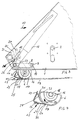
- the mower has frame 1.
- coupling elements for attachment to, for example, a tractor are arranged on the front of the frame 1.
- the mowing drum 3 is driven in a manner not shown and described by a power source rotating in the direction of arrow 5.
- the support roller 6 is arranged on the frame 1 in a height-adjustable manner.
- the mower has the grass hanging device 7.
- the support roller 6 is arranged with the support elements designed as support arms 8 by means of the bolts 9 on the frame 1 in the height direction so as to be pivotable about an axis 11 running transversely to the working direction 10.
- the height adjustment device designed as a lifting spindle 12 acts on the support arms 8. Via the lifting spindle 12, the support arms and the pivot axis 11 extending through the bolt 9, the support roller 6 can be pivoted relative to the frame 1 to adjust the height of the cutting tools 4 to the ground surface 13.
- the bolt 14, which connects the lifting spindles 12 to the support arms 8, is guided in an elongated hole 15 arranged in the frame 1. By the length of this elongated hole 15 also defines the adjustment range of the roller 6 relative to the frame 1 and the working tools 4.
- the support roller 6 is rotatably mounted in the bearing block 16 fastened to the support arms 8.
- the backup roller 6 has a closed roller jacket 17.
- the roller 6 is rotatably mounted in the bearing block 16 via the axle shafts 18 arranged on the support roller 6.
- a wiper device 19 is arranged on the back of the support roller 6.
- This scraper device 19 has the angular holding element 20 to which the scraper strip 21 is fastened.
- the angular holding element 20 is connected to the holding arms 23 of the adjusting device 24 by means of supports 22.
- the holding arms 23 are rotatably mounted on the axle shafts 18 with respect to the support arms 8.
- the carrier 22 of the wiper device 19 are designed as leaf springs, so that the carrier 22 are resilient.
- the stripper strip 21 is pressed against the roller jacket 17 of the support roller 6 by means of the leaf springs 22.
- the scraper strip 21 is located with its scraper edge 24 on the roller jacket 17 near the bottom surface 13 or the upper area of the turf 25.
- the holding arms 23 have on their end facing away from the axle shaft 18 an adjusting device 26 which interacts with the frame 1.
- This adjusting device 26 consists of a curved elongated hole 27, in which bolt-like elements 28 fastened to the holding arms 23 engage. This ensures that the scraper 21 remains in the same position relative to the bottom surface 13 when the height adjustment 12 of the support roller 6 is actuated, because this adjusting device 26 counteracts the pivoting movement of the roller 6.
- the adjusting device 26 is thus arranged between the brackets 23 of the wiper device 19 and the frame 1.
- Scraper 21 adjustable in such a way that when the roller 6 is adjusted in height relative to the working tools 4, the position of the scraper 21 on the roller 6 relative to the bottom surface 13 remains practically unchanged.
- the position close to the ground of the scraper 21 is to be ensured so that the crop to be scraped off, which accumulates in the gap between the roller jacket 17 of the supporting roller 6 and the scraper 21 despite the sharp scraper edge 21, is brushed out by the turf 25 streaking past.
- the leaf spring 23 ensures that the stripper 21 is pressed against the roller jacket 17.
- the stripper 21 is constantly in contact with the roller jacket 17.
- the scraper 21 can also avoid any obstacles.
- the holding element 29 of the scraper strip 21 has on its side 31 facing the roller shell 17 of the support roller 6 an at least approximately adapted to the contour of the roller shell 17.
- the gap 32 between the roller jacket 17, the support roller 6 and the holding element 29 of the scraper strip 21 is initially at least approximately constant when viewed in the direction of rotation 33 of the support roller 6 and then widens.
- the scraper strip 21 and the holding element 29 extend over the entire working width of the support roller 6. Die Wiper strip 21 is adjustably attached to the holding element 29 so that when the wiper strip 21 wears, it is readjusted in the direction of arrow 34.
Landscapes
- Life Sciences & Earth Sciences (AREA)
- Environmental Sciences (AREA)
- Engineering & Computer Science (AREA)
- Mechanical Engineering (AREA)
- Soil Sciences (AREA)
- Harvester Elements (AREA)
- Soil Working Implements (AREA)
Applications Claiming Priority (4)
| Application Number | Priority Date | Filing Date | Title |
|---|---|---|---|
| DE4238603 | 1992-11-16 | ||
| DE19924238603 DE4238603A1 (de) | 1992-11-16 | 1992-11-16 | Stützwalze |
| DE4243251A DE4243251A1 (de) | 1992-11-16 | 1992-12-19 | Stützwalze |
| DE4243251 | 1992-12-19 |
Publications (3)
| Publication Number | Publication Date |
|---|---|
| EP0598266A2 true EP0598266A2 (fr) | 1994-05-25 |
| EP0598266A3 EP0598266A3 (en) | 1994-09-14 |
| EP0598266B1 EP0598266B1 (fr) | 1997-02-05 |
Family
ID=25920481
Family Applications (1)
| Application Number | Title | Priority Date | Filing Date |
|---|---|---|---|
| EP93117637A Expired - Lifetime EP0598266B1 (fr) | 1992-11-16 | 1993-10-30 | Rouleau support |
Country Status (2)
| Country | Link |
|---|---|
| EP (1) | EP0598266B1 (fr) |
| DE (2) | DE4243251A1 (fr) |
Cited By (1)
| Publication number | Priority date | Publication date | Assignee | Title |
|---|---|---|---|---|
| EP2997802A1 (fr) * | 2014-09-17 | 2016-03-23 | Müthing GmbH & Co. KG | Dispositif de travail agricole |
Families Citing this family (1)
| Publication number | Priority date | Publication date | Assignee | Title |
|---|---|---|---|---|
| DE102015118369A1 (de) * | 2015-10-28 | 2017-05-04 | Amazonen-Werke H. Dreyer Gmbh & Co. Kg | Mobile Bearbeitungseinheit zur Pflege von Grünflächen |
Family Cites Families (7)
| Publication number | Priority date | Publication date | Assignee | Title |
|---|---|---|---|---|
| GB301978A (en) * | 1927-09-21 | 1928-12-13 | Louis John Tibbenham | Improvements in lawn mowers |
| GB500703A (en) * | 1938-07-25 | 1939-02-14 | Benjamin Herbert Baker | Improvements relating to garden and like rollers |
| US2815524A (en) * | 1954-07-26 | 1957-12-10 | Mitchell Co John E | Mower roller scraper |
| NL8601048A (nl) * | 1986-04-24 | 1987-11-16 | Lely Nv C Van Der | Grondbewerkingsmachine. |
| EP0305601B1 (fr) * | 1987-09-03 | 1992-04-29 | C. van der Lely N.V. | Appareil pour cultiver le sol |
| DE8913171U1 (de) * | 1989-11-07 | 1990-01-18 | Rabewerk Heinrich Clausing, 4515 Bad Essen | Bodenbearbeitungsgerät |
| US5228277A (en) * | 1992-01-23 | 1993-07-20 | Deere & Company | Rear discharge reel mower having multi-purpose rotary brush |
-
1992
- 1992-12-19 DE DE4243251A patent/DE4243251A1/de not_active Ceased
-
1993
- 1993-10-30 DE DE59305391T patent/DE59305391D1/de not_active Expired - Fee Related
- 1993-10-30 EP EP93117637A patent/EP0598266B1/fr not_active Expired - Lifetime
Cited By (1)
| Publication number | Priority date | Publication date | Assignee | Title |
|---|---|---|---|---|
| EP2997802A1 (fr) * | 2014-09-17 | 2016-03-23 | Müthing GmbH & Co. KG | Dispositif de travail agricole |
Also Published As
| Publication number | Publication date |
|---|---|
| DE59305391D1 (de) | 1997-03-20 |
| EP0598266A3 (en) | 1994-09-14 |
| DE4243251A1 (de) | 1994-07-28 |
| EP0598266B1 (fr) | 1997-02-05 |
Similar Documents
| Publication | Publication Date | Title |
|---|---|---|
| EP0552709A1 (fr) | Tondeuse à gazon | |
| DE2413588A1 (de) | Rasenmaeher | |
| CH648369A5 (de) | Spur- oder planiergeraet fuer ski-loipen bzw. ski-pisten. | |
| EP0426960A2 (fr) | Bineuse pour machine agricole | |
| DE2921183B2 (de) | Furchenöffner für Sä- oder Pflanzmaschinen | |
| DE3422254C2 (fr) | ||
| DE2641956C3 (de) | Pflug mit einem um eine vertikale Achse schwenkbaren Hauptrahmen, der aus zwei um eine gemeinsame horizontale Achse schwenkbaren Rahmenabschnitten besteht | |
| EP0486473B1 (fr) | Machine agricole de préparation du sol | |
| EP0712568A1 (fr) | Dispositif à faucher, aérer et/ou ramasser | |
| DE60112351T2 (de) | Heuwerbungsmaschine | |
| EP0598266B1 (fr) | Rouleau support | |
| DE19954423B4 (de) | Landwirtschaftliche Bestellkombination mit günstiger Schwerpunktsverlagerung | |
| DE2824808A1 (de) | Nivellier- und kruemlerwalzenanordnung | |
| EP0804869B1 (fr) | Charrue attelable ou accrochable | |
| DE8803705U1 (de) | Bodenbearbeitungsgerät mit Teleskop-Schutzklappe | |
| DE69000892T2 (de) | Verbesserung an einem Säsystem, Sämaschine und kombinierte Maschine zur Saatbettherrichtung und zum Säen mit einem solchen Säsystem. | |
| EP0161621A2 (fr) | Machine pour le travail du sol | |
| DE4238603A1 (de) | Stützwalze | |
| EP0157840B1 (fr) | Installation pour la formation de sillons a parois paralleles dans des prairies et des pelouses | |
| EP1254593B1 (fr) | Outil pour émietter des sols grossièrement travaillés | |
| DE963561C (de) | Bodenfraese | |
| DE4138633A1 (de) | Verstopfungs-ausraeumer zwischen den saescharen, vornehmlich stiefelsaescharen, von drillmaschinen bekannter bauarten | |
| DE2943732A1 (de) | Arbeitsgeraet zur saatbettherrichtung | |
| DE3125379A1 (de) | Pflugzusatzgeraet | |
| EP0407725A2 (fr) | Outil de travail du sol, particulièrement herse circulaire |
Legal Events
| Date | Code | Title | Description |
|---|---|---|---|
| PUAI | Public reference made under article 153(3) epc to a published international application that has entered the european phase |
Free format text: ORIGINAL CODE: 0009012 |
|
| AK | Designated contracting states |
Kind code of ref document: A2 Designated state(s): DE FR GB NL |
|
| PUAL | Search report despatched |
Free format text: ORIGINAL CODE: 0009013 |
|
| AK | Designated contracting states |
Kind code of ref document: A3 Designated state(s): DE FR GB NL |
|
| 17P | Request for examination filed |
Effective date: 19941115 |
|
| 17Q | First examination report despatched |
Effective date: 19960216 |
|
| GRAG | Despatch of communication of intention to grant |
Free format text: ORIGINAL CODE: EPIDOS AGRA |
|
| GRAH | Despatch of communication of intention to grant a patent |
Free format text: ORIGINAL CODE: EPIDOS IGRA |
|
| GRAH | Despatch of communication of intention to grant a patent |
Free format text: ORIGINAL CODE: EPIDOS IGRA |
|
| GRAA | (expected) grant |
Free format text: ORIGINAL CODE: 0009210 |
|
| AK | Designated contracting states |
Kind code of ref document: B1 Designated state(s): DE FR GB NL |
|
| PG25 | Lapsed in a contracting state [announced via postgrant information from national office to epo] |
Ref country code: NL Free format text: LAPSE BECAUSE OF FAILURE TO SUBMIT A TRANSLATION OF THE DESCRIPTION OR TO PAY THE FEE WITHIN THE PRESCRIBED TIME-LIMIT Effective date: 19970205 Ref country code: GB Effective date: 19970205 Ref country code: FR Effective date: 19970205 |
|
| REF | Corresponds to: |
Ref document number: 59305391 Country of ref document: DE Date of ref document: 19970320 |
|
| NLV1 | Nl: lapsed or annulled due to failure to fulfill the requirements of art. 29p and 29m of the patents act | ||
| EN | Fr: translation not filed | ||
| GBV | Gb: ep patent (uk) treated as always having been void in accordance with gb section 77(7)/1977 [no translation filed] |
Effective date: 19970205 |
|
| PLBE | No opposition filed within time limit |
Free format text: ORIGINAL CODE: 0009261 |
|
| STAA | Information on the status of an ep patent application or granted ep patent |
Free format text: STATUS: NO OPPOSITION FILED WITHIN TIME LIMIT |
|
| 26N | No opposition filed | ||
| PGFP | Annual fee paid to national office [announced via postgrant information from national office to epo] |
Ref country code: DE Payment date: 19991021 Year of fee payment: 7 |
|
| PG25 | Lapsed in a contracting state [announced via postgrant information from national office to epo] |
Ref country code: DE Free format text: LAPSE BECAUSE OF NON-PAYMENT OF DUE FEES Effective date: 20010703 |