EP2997802A1 - Dispositif de travail agricole - Google Patents
Dispositif de travail agricole Download PDFInfo
- Publication number
- EP2997802A1 EP2997802A1 EP14003221.0A EP14003221A EP2997802A1 EP 2997802 A1 EP2997802 A1 EP 2997802A1 EP 14003221 A EP14003221 A EP 14003221A EP 2997802 A1 EP2997802 A1 EP 2997802A1
- Authority
- EP
- European Patent Office
- Prior art keywords
- support roller
- gutleitblech
- working
- holding
- rotor
- Prior art date
- Legal status (The legal status is an assumption and is not a legal conclusion. Google has not performed a legal analysis and makes no representation as to the accuracy of the status listed.)
- Granted
Links
Images

Classifications
-
- A—HUMAN NECESSITIES
- A01—AGRICULTURE; FORESTRY; ANIMAL HUSBANDRY; HUNTING; TRAPPING; FISHING
- A01B—SOIL WORKING IN AGRICULTURE OR FORESTRY; PARTS, DETAILS, OR ACCESSORIES OF AGRICULTURAL MACHINES OR IMPLEMENTS, IN GENERAL
- A01B33/00—Tilling implements with rotary driven tools, e.g. in combination with fertiliser distributors or seeders, with grubbing chains, with sloping axles, with driven discs
- A01B33/02—Tilling implements with rotary driven tools, e.g. in combination with fertiliser distributors or seeders, with grubbing chains, with sloping axles, with driven discs with tools on horizontal shaft transverse to direction of travel
-
- A—HUMAN NECESSITIES
- A01—AGRICULTURE; FORESTRY; ANIMAL HUSBANDRY; HUNTING; TRAPPING; FISHING
- A01D—HARVESTING; MOWING
- A01D34/00—Mowers; Mowing apparatus of harvesters
- A01D34/01—Mowers; Mowing apparatus of harvesters characterised by features relating to the type of cutting apparatus
- A01D34/412—Mowers; Mowing apparatus of harvesters characterised by features relating to the type of cutting apparatus having rotating cutters
- A01D34/42—Mowers; Mowing apparatus of harvesters characterised by features relating to the type of cutting apparatus having rotating cutters having cutters rotating about a horizontal axis, e.g. cutting-cylinders
- A01D34/43—Mowers; Mowing apparatus of harvesters characterised by features relating to the type of cutting apparatus having rotating cutters having cutters rotating about a horizontal axis, e.g. cutting-cylinders mounted on a vehicle, e.g. a tractor, or drawn by an animal or a vehicle
- A01D34/435—Flail harvesters or mowers
Definitions
- the invention relates to an agricultural working device, in particular as a mulching, mulching or milling device with a work rotor, at least one support roller and at least one cutting edge.
- Such agricultural working devices for separating and crushing Bodenbewachs such as grass, but also plant stubble found as separation and crushing devices, especially as mulch, mulching mowers or tiller wide application, inter alia, in the brownfield and landscape management and agriculture. They are used there for mowing and shredding plant growth, plant residues and biomass of various kinds, such as grass, catch crops, plant stoppers of cereals, oilseed rape, maize, branches or bushes. This is separated from the working device, picked up, crushed by a working rotor and returned to the ground. The divided and distributed plant material on the ground is then left on the ground and rots quickly due to its Nature. It also serves as fertilizer for the soil, humus formation and field hygiene measures.
- Such implements usually have movable, positionable sub-elements of the device housing itself or rear-adjustable housing flaps, which affect the stability of the device and usually violate valid safety standards.
- the invention has for its object to overcome the drawbacks mentioned above and to develop a working device such as a mulching, mulching or milling device, in which effective at work components can be easily, quickly and inexpensively adjusted on site.
- the object is achieved in a device according to the invention primarily by the positioning of at least one Support roller in at least two holding positions in the longitudinal or direction of travel of the device and by at least one adjustable Gutleitblech.
- the invention further provides that in the interior of the housing, a Gutleitblech is pivotally mounted and / or that at least one cutting edge is arranged in stages or continuously adjustable relative to the working rotor and / or that a Abstreiferschiene is adjustably mounted on the housing.
- An embodiment of the invention provides that the support roller is pivotally supported at holding points and is pivotable about them in their holding positions.
- One of the two positions can be characterized in that the distance of the support roller to the work rotor is low. As a result, the exiting plant residues meet in the direction of travel behind the back-up roller on the ground. In this position, an optimal depth guidance of the working rotor is guaranteed. This position is chosen especially for dry light good, which can be easily promoted by the work rotor on the support roller.
- the support roller In a second position, the support roller can be as far away from the existing work rotor. In this position, the shredded plant matter is placed on the ground in front of the support roller.
- This has the advantage, in particular in humid conditions and moist, sticky soils, that the support roller runs on the plant material, which reduces the adhesion to the support roller in particular under such conditions and prevents it altogether in cooperation with a wiper rail, thus also providing a uniform depth guidance of the device ensured over a constant angular diameter of the support roller is.
- the support roller Seen in the direction of travel, supports the mulching device at the rearmost part of the housing and thus increases the stability of the entire body, especially in rough terrain.
- the support roller may be mounted depth-adjustable in their holding positions in each case via a guide. This allows optimum depth control of all existing components according to the circumstances of the field of application, in particular the conditions of the existing terrain and the selected different working and cutting height above the ground or the depth of action in the ground.
- the support roller can also be moved stepwise and steplessly in the holding positions. This allows the freedom to find the ideal position for the particular application.
- the position of the support roller can be adjusted according to the terrain shape and the desired work result.
- the escape of dust and plant remains from the inside of the working device severely restricted, resulting in a significant reduction in the dust load of subsequent equipment or vehicles, in particular with regard to radiator contamination of front-wheel drive vehicles.
- the use of mechanical fasteners allows a large margin in the Configuration of the holding device for the support roller, as well as an efficient support and displacement possibility of the support roller.
- the replacement by or supplement with hydraulic elements leads to an effective adjustment and holding the back-up roll.
- the invention also includes the embodiment of the device only with the inventively provided positioning of the support roller;
- a pivotable Gutleitblech does not necessarily have to be provided, which, however, preferably supports the action of the positionable support roller, so that in a preferred manner, all described preferred embodiments are also based thereon.
- the pivotable arrangement of a Gutleitblechs influence on the movement of the plant material in the interior of the housing, the so-called conveyor channel can be taken. If the Gutleitblech, for example, swung close to the work rotor, this arrangement leads the plant material close to the work rotor over, so that it is passed in the vicinity of the ground. This position of the Gutleitblechs is provided in particular provided by the work rotor Asked support roller.
- a development of the invention can provide that the Gutleitblech is provided with a holder and / or an adjustment.
- the mechanical design of the device according to the invention provides a simple and efficient way to move the Gutleitblech.
- With regard to the stepless adjustment of the Gutleitblechs is through the use of hydraulic components, a further low-wear and effective method for this purpose.
- the movement of the Gutleitblechs be coupled with the movement of the support roller.
- the shredder emerging from the shredder comes in the direction of travel in front of the support roller on the ground, while it is directed in a different positioning of the components on the support roller over, so seen in the direction of travel behind the back-up roller reaches the ground.
- the inventively provided adjustability of the cutting edge of the cutting gap can be changed as a distance between the cutting edge and an existing work rotor. In particular, this can be done with respect to the plant material to be processed during use.
- the adjustment allows on the one hand the adaptation to the different Gutkonsistenzen, but also the generation of different work qualities and work efficiencies, depending on the requirement.
- the thus possible cutting gap variation with simple mechanical adjustment offers an efficient adaptation to different requirements as well as to different performance requirements for the driving vehicles.
- an adjustable cutting edge can be moved or fixed by mechanical devices and / or hydraulic components.
- the design by mechanical elements allows a quick and reliable conversion before and during operation and a correspondingly fast adaptation to the prevailing conditions.
- At least one adjustable cutting edge may have a straight, serrated or wavy profile.
- the profile type is thus adaptable to the circumstances of the application, in particular to the consistency and dimensions of the plant material to be processed and shredded. This allows optimum cutting and crushing quality of the comminuted biomass.
- the profile of the at least one adjustable cutting edge can be configured with or without interruptions.
- a further adaptation to the existing plant material is possible as well as the advantageous exchange possibility of individual elements.
- a staggered construction with several, successively mounted, adjustable cutting edges is possible.
- the wiper rail is supported multiple times on the entire housing width and thus has a high stability and working accuracy over the conventional known Abstreiferbalken with an exclusive 2-point attachment only at the outer points of the support roller itself, which due to the lack of stability leads to bending and poor cleaning function.
- a mulching or mulching mower or tiller may have an adjustability of at least two or all four of the backing roll, wiper rail, baffle, and cutting edge components.
- a mulching or mulching mower or tiller may have an adjustability of at least two or all four of the backing roll, wiper rail, baffle, and cutting edge components.
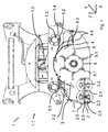
- Fig. 1 In the following, reference is made in part to a standard Cartesian coordinate system, which is drawn to the right: where X denotes the longitudinal axis in the direction of travel, Y the transverse axis and Z the vertical axis of the working device 1.
- the working device 1 in particular in the form of a mulching device is an attachment that as a front and / or rear attachment in a conventional manner via a three-point hitch 1.1 at the front or at the rear of a vehicle, such as a tractor or another carrier vehicle, attachable.
- the mulching device has a support roller 2. This is in the one, in the drawing - left - position continuously, in the other - shown in dashed lines in the right - position. This will be discussed in detail below.
- the device 1 has a working rotor 5, which is driven by a drive unit 1.2.
- the drive can be done via mechanical transmission with lateral extension shafts, but also hydraulically or electrically.
- a displacement device 1.3 for the three-point attachment head is provided on each mounting side, the horizontal fastening elements 1.4, here in the form of fixed tubes.
- the support roller itself is rotatably mounted on pivotable holding plates 2.4, which are provided axially on both sides of the support roller 2.
- the holding plates 2.4 are mounted pivotably about a pivot axis 2.1 on the housing of the device 1.
- In the holding plate 2.4 are provided over the height (here three) openings 2.5, by means of which the holding plate 2.4 can be fixed in a certain pivot position with a desired depth above the ground on the housing by means of screws 2.3.
- the height or depth of the holding plate 2.4 and thus also the support roller 2 is set by selecting the apertures 2.5, via which the attachment is effected by means of the screw 2.3 on the housing.
- the working rotor 5 can be designed as a cylinder and is driven for example via a working shaft of a tractor.
- working tools 5.1 are attached, which are equipped in the illustrated embodiment as a swivel flail or work knife. These are radially outwardly extending and curved blades. Other designs such as straight or curved knife blades or plate sliders are also possible and common. They serve to separate the plant material from the ground, to absorb and shred.
- the working rotor 5 is driven counter to the direction of travel, in the illustrated embodiment, it thus rotates counterclockwise about its axis in the transverse direction Y.
- a curved cover 5.2 In the upper region of the working rotor 5 is enclosed by a curved cover 5.2 with radial distance. At this are, facing the working rotor 5, fixed or pivotable counter cutting 5.3, which cooperate with the flails or cutting blades 5.1 of the working rotor 5 to increase the Aufschlag- or crushing of the mulching 1.
- the support roller 2 can be pivoted about 180 ° about the pivot axis 2.1.
- the support roller 2 can in particular assume a position as drawn through in Fig. 1 and also in Fig. 2 is shown.
- a first position of a Gutleitblechs 3 is also in Fig. 1 and 2 shown. It is pivotable in the interior of the housing about a pivot axis 3.1, but in suitable pivoting positions.
- a guide device 3.2 in the form of elongated holes predetermines the degree of pivotability of the Gutleitblechs 3.
- the Gutleitblech 3 is fixed by means of screws in the slots 3.2 in desired positions. For pivoting the Gutleitblechs 3, the screws of the guide device 3.2 are released, the Gutleitblech 3 pivoted to the desired position and then the screws are again tightened in the guide device 3.2 (the slots).
- the Gutleitblech 3 is a second characteristic position of the Gutleitblechs 3 in accordance with the delivered on the work rotor 5 support roller 2 shown such that the mulch can be funded by the working rotor 5 on the support roller 2 away.
- the Gutleitblech 3 is here pivoted to the working rotor 5 towanden front side of the housing out.
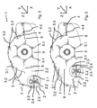
- Fig. 1 It shows a working edge 5 on the side facing away from the support roller 2 side cutting edge 4. It extends along the working rotor 5 in the transverse direction Y and in the longitudinal or direction of travel X of the device has a finite width. It is detachably fixed to the housing of the mulching device 1. It can be fastened via fastening elements 4.4, which are designed here as screws. After loosening the fastening elements 4.4, the cutting edge in the direction of travel X is displaced. In particular, it can be displaced until the distance of the cutting edge 4 from the working rotor 5 is minimal ( Fig. 2 ) or maximum ( Fig. 3 ), this end position is limited by the location of corresponding slots. Also every intermediate position can be adjusted.
- the mulching device 1 is attached to a vehicle, such as a tractor.
- the working rotor 5 is driven via a working shaft of the vehicle.
- the working device 1 is supported by the support roller 2 on the ground and moves with the tractor in the direction of travel X.
- the flail take 5.1 of the working rotor 5 from the plant growth and / or take on the soil located plant matter and guide it through the Rotary movement of the working rotor 5 about the axis extending in the transverse direction Y to the cutting edge 4.
- the position the cutting edge 4 regulates the opening to a conveying channel 6 extending beyond it.
- the cut material moving along the conveying channel 6 as a result of the direction of rotation of the working rotor 5 is further comminuted, for which purpose the counter cutters 5.3 serve in the mulching body. It thus arrives in the rear area behind the working rotor 5.
- the position of the Gutleitblechs 3, the further promotion of the shredded cuttings is set.
- the Gutleitblech 3 can be pivoted to its second position.
- the screw is released in the guide device 3.2 and the Gutleitblech 3 pivoted about the bearing 3.1 along the guide device 3.2 and then fixed again in its final position by the screw of the guide device 3.2.
- the Gutleitblech 3 assumes its second position. In this position, it is almost on the inner wall of the housing body 1 at.
- the support roller 2 is brought into its second position: For this purpose, the fastening screws 2.3 are removed and the support roller 2 is pivoted 180 ° about the axis in the transverse direction Y about the pivot axis 2.1. It thus reaches the in Fig. 3 shown position. Here, the fastening screws 2.3 are attached and fixed the support roller 2 in this position.
- the delivery channel 6 of the passing crop is reshaped.
- the working rotor 5 passing and crushed cut material passes through the changed conveyor channel 6 in the direction of travel X seen behind the support roller 2 and on the working rotor 5 side facing away from the ground. It also reduces the escape of dust and shredded parts of plants and the pollution of subsequent vehicles and equipment.
- Fig. 4 shows various embodiments of one or more cut edges 4. Left is a straight profile 4.1, in the middle of a serrated profile 4.2 and right a corrugated profile 4.3 shown, which are each attached by fastening elements 4.4 on the housing body 1. Contrary to the direction of travel X, this is followed by the working rotor 5 with attached thereto tugs 5.1 in staggered arrangement. Behind the support roller 2 can be seen.
Landscapes
- Life Sciences & Earth Sciences (AREA)
- Environmental Sciences (AREA)
- Engineering & Computer Science (AREA)
- Mechanical Engineering (AREA)
- Soil Sciences (AREA)
- Harvester Elements (AREA)
- Soil Working Implements (AREA)
- Hydraulic Clutches, Magnetic Clutches, Fluid Clutches, And Fluid Joints (AREA)
Priority Applications (6)
| Application Number | Priority Date | Filing Date | Title |
|---|---|---|---|
| EP14003221.0A EP2997802B1 (fr) | 2014-09-17 | 2014-09-17 | Dispositif de travail agricole |
| HUE14003221A HUE035127T2 (en) | 2014-09-17 | 2014-09-17 | Agricultural work equipment |
| PL14003221T PL2997802T3 (pl) | 2014-09-17 | 2014-09-17 | Rolnicze urządzenie robocze |
| NO14003221A NO2997802T3 (fr) | 2014-09-17 | 2014-09-17 | |
| SI201430499T SI2997802T1 (en) | 2014-09-17 | 2014-09-17 | Agricultural working device |
| ES14003221.0T ES2647877T3 (es) | 2014-09-17 | 2014-09-17 | Dispositivo de trabajo agrícola |
Applications Claiming Priority (1)
| Application Number | Priority Date | Filing Date | Title |
|---|---|---|---|
| EP14003221.0A EP2997802B1 (fr) | 2014-09-17 | 2014-09-17 | Dispositif de travail agricole |
Publications (2)
| Publication Number | Publication Date |
|---|---|
| EP2997802A1 true EP2997802A1 (fr) | 2016-03-23 |
| EP2997802B1 EP2997802B1 (fr) | 2017-08-30 |
Family
ID=51570248
Family Applications (1)
| Application Number | Title | Priority Date | Filing Date |
|---|---|---|---|
| EP14003221.0A Active EP2997802B1 (fr) | 2014-09-17 | 2014-09-17 | Dispositif de travail agricole |
Country Status (6)
| Country | Link |
|---|---|
| EP (1) | EP2997802B1 (fr) |
| ES (1) | ES2647877T3 (fr) |
| HU (1) | HUE035127T2 (fr) |
| NO (1) | NO2997802T3 (fr) |
| PL (1) | PL2997802T3 (fr) |
| SI (1) | SI2997802T1 (fr) |
Cited By (7)
| Publication number | Priority date | Publication date | Assignee | Title |
|---|---|---|---|---|
| WO2018215983A1 (fr) * | 2017-05-26 | 2018-11-29 | Tierre Group S.R.L. | Machine améliorée de coupe |
| DE102017008126A1 (de) * | 2017-08-30 | 2019-02-28 | Müthing GmbH & Co. KG | Landwirtschaftliche Arbeitsvorrichtung |
| US10375891B2 (en) | 2016-07-05 | 2019-08-13 | Charles H. Martin | Agricultural device |
| IT201800010048A1 (it) * | 2018-11-05 | 2020-05-05 | Dragone S R L | Trinciatrice per la lavorazione superficiale del terreno |
| WO2021209250A1 (fr) * | 2020-04-17 | 2021-10-21 | Müthing GmbH & Co. KG | Broyeur |
| EP3939411A2 (fr) | 2020-07-15 | 2022-01-19 | Müthing GmbH & Co. KG | Dispositif et procédé de traitement des surfaces de sol |
| DE102020123519A1 (de) | 2020-09-09 | 2022-03-10 | Müthing GmbH & Co. KG | Vorrichtung und Verfahren zum Bearbeiten von Bodenbewuchsflächen |
Citations (6)
| Publication number | Priority date | Publication date | Assignee | Title |
|---|---|---|---|---|
| EP0598266A2 (fr) * | 1992-11-16 | 1994-05-25 | Amazonen-Werke H. Dreyer GmbH & Co. KG | Rouleau support |
| DE10257954A1 (de) * | 2002-12-12 | 2004-07-01 | Amazonen-Werke H. Dreyer Gmbh & Co. Kg | Mähgerät |
| EP1472926A1 (fr) * | 2003-04-30 | 2004-11-03 | Deere & Company | Méthode et appareil pour régler et maintenir la distance tambour-contre couteau |
| WO2005009109A1 (fr) * | 2003-07-25 | 2005-02-03 | Bcs S.P.A. | Machine servant a couper et triturer l'herbe et d'autres produits vegetaux |
| EP2052596A1 (fr) * | 2007-10-23 | 2009-04-29 | Deere & Company | Axe de pivot ajustable pour ensemble de contre-lame |
| EP2476309A1 (fr) * | 2011-01-17 | 2012-07-18 | Renzo Carboni | Machine de travail pour préparer et traiter la litière pour volaillers |
-
2014
- 2014-09-17 SI SI201430499T patent/SI2997802T1/en unknown
- 2014-09-17 PL PL14003221T patent/PL2997802T3/pl unknown
- 2014-09-17 HU HUE14003221A patent/HUE035127T2/en unknown
- 2014-09-17 NO NO14003221A patent/NO2997802T3/no unknown
- 2014-09-17 ES ES14003221.0T patent/ES2647877T3/es active Active
- 2014-09-17 EP EP14003221.0A patent/EP2997802B1/fr active Active
Patent Citations (6)
| Publication number | Priority date | Publication date | Assignee | Title |
|---|---|---|---|---|
| EP0598266A2 (fr) * | 1992-11-16 | 1994-05-25 | Amazonen-Werke H. Dreyer GmbH & Co. KG | Rouleau support |
| DE10257954A1 (de) * | 2002-12-12 | 2004-07-01 | Amazonen-Werke H. Dreyer Gmbh & Co. Kg | Mähgerät |
| EP1472926A1 (fr) * | 2003-04-30 | 2004-11-03 | Deere & Company | Méthode et appareil pour régler et maintenir la distance tambour-contre couteau |
| WO2005009109A1 (fr) * | 2003-07-25 | 2005-02-03 | Bcs S.P.A. | Machine servant a couper et triturer l'herbe et d'autres produits vegetaux |
| EP2052596A1 (fr) * | 2007-10-23 | 2009-04-29 | Deere & Company | Axe de pivot ajustable pour ensemble de contre-lame |
| EP2476309A1 (fr) * | 2011-01-17 | 2012-07-18 | Renzo Carboni | Machine de travail pour préparer et traiter la litière pour volaillers |
Cited By (12)
| Publication number | Priority date | Publication date | Assignee | Title |
|---|---|---|---|---|
| US10375891B2 (en) | 2016-07-05 | 2019-08-13 | Charles H. Martin | Agricultural device |
| WO2018215983A1 (fr) * | 2017-05-26 | 2018-11-29 | Tierre Group S.R.L. | Machine améliorée de coupe |
| DE102017008126A1 (de) * | 2017-08-30 | 2019-02-28 | Müthing GmbH & Co. KG | Landwirtschaftliche Arbeitsvorrichtung |
| US20190059216A1 (en) * | 2017-08-30 | 2019-02-28 | Müthing GmbH & Co. KG | Agricultural working apparatus |
| US10980175B2 (en) | 2017-08-30 | 2021-04-20 | Müthing GmbH & Co. KG | Agricultural apparatus for comminution of biomass |
| AU2018217274B2 (en) * | 2017-08-30 | 2023-11-09 | Müthing GmbH & Co. KG | Agricultural Working Apparatus |
| IT201800010048A1 (it) * | 2018-11-05 | 2020-05-05 | Dragone S R L | Trinciatrice per la lavorazione superficiale del terreno |
| WO2021209250A1 (fr) * | 2020-04-17 | 2021-10-21 | Müthing GmbH & Co. KG | Broyeur |
| EP3939411A2 (fr) | 2020-07-15 | 2022-01-19 | Müthing GmbH & Co. KG | Dispositif et procédé de traitement des surfaces de sol |
| DE102020118660A1 (de) | 2020-07-15 | 2022-01-20 | Müthing GmbH & Co. KG | Vorrichtung und Verfahren zum Bearbeiten von Bodenflächen |
| DE102020123519A1 (de) | 2020-09-09 | 2022-03-10 | Müthing GmbH & Co. KG | Vorrichtung und Verfahren zum Bearbeiten von Bodenbewuchsflächen |
| EP3967123A1 (fr) | 2020-09-09 | 2022-03-16 | Müthing GmbH & Co. KG | Dispositif et procédé de traitement des surfaces de salissure du sol |
Also Published As
| Publication number | Publication date |
|---|---|
| SI2997802T1 (en) | 2018-01-31 |
| PL2997802T3 (pl) | 2018-03-30 |
| ES2647877T3 (es) | 2017-12-27 |
| NO2997802T3 (fr) | 2018-01-27 |
| EP2997802B1 (fr) | 2017-08-30 |
| HUE035127T2 (en) | 2018-05-02 |
Similar Documents
| Publication | Publication Date | Title |
|---|---|---|
| EP2997802B1 (fr) | Dispositif de travail agricole | |
| DE602006000326T2 (de) | Schwenkbares Streugerät | |
| EP3272199B1 (fr) | Broyeur destiné au traitement de résidus de cultures dans un champ | |
| EP3479677B1 (fr) | Dispositif de travail agricole | |
| DE102007009587A1 (de) | Vorrichtung zur Einstellung der Position des Nachbeschleunigungsorgans in einer landwirtschaftlichen Erntemaschine | |
| EP1671532B1 (fr) | Rotor hacheur | |
| EP3016494B1 (fr) | Appareil agricole et procédé de traitement de chaumes végétaux | |
| EP1932416A1 (fr) | Dispositif muni d'une première et d'une seconde unité de travail | |
| DE102021114960A1 (de) | Erntevorsatz zur Ernte stängelartiger Pflanzen mit drehzahlveränderlich angetriebenem Mulchgerät | |
| DE3830141C1 (en) | Method and apparatus for working the growth between the rows of young standing maize plants in maize-cultivation areas | |
| EP1483953B1 (fr) | Dispositif de coupe à hauteur pour moissoneuse-batteuse | |
| DE69013579T2 (de) | Verbesserung an einem Säsystem, Sämaschine und kombinierte Maschine zur Saatbeeterrichtung und zum Säen mit einem solchen System. | |
| EP3354126A1 (fr) | Couteau et tambour de hachoir pour une ramasseuse-hacheuse | |
| EP3449710B1 (fr) | Dispositif de travail agricole sous forme de faucheuse à fléau | |
| DE102017123850A1 (de) | Mulchgerät mit Schlegel- und Sichelmähwerk | |
| WO2014198599A1 (fr) | Moissonneuse pour moissonner des plantes a tiges | |
| DE102012102084B4 (de) | Verlade- und Transportvorrichtung für landwirtschaftliche Schneidwerke | |
| DE202014010566U1 (de) | Landwirtschaftliche Arbeitsvorrichtung | |
| DE102005049716B4 (de) | Mähhacker für Pflanzen | |
| DE69000892T2 (de) | Verbesserung an einem Säsystem, Sämaschine und kombinierte Maschine zur Saatbettherrichtung und zum Säen mit einem solchen Säsystem. | |
| EP4054312B1 (fr) | Agencement d'équipement, véhicule de travail et procédé en particulier pour maintenir des zones vertes, fauchage, travail du sol, ou récolte de cultures brutes ou céréalières | |
| EP2882274B1 (fr) | Dispositif pour entailler une couche de matière organique couchée sur la surface du sol, et utilisation de ce dispositif | |
| DE102008015242A1 (de) | Heckenpflegevorrichtung | |
| DE69705198T2 (de) | Erntemaschine | |
| DE3750243T2 (de) | Ernteaufbereitungsmaschine. |
Legal Events
| Date | Code | Title | Description |
|---|---|---|---|
| PUAI | Public reference made under article 153(3) epc to a published international application that has entered the european phase |
Free format text: ORIGINAL CODE: 0009012 |
|
| 17P | Request for examination filed |
Effective date: 20150921 |
|
| AK | Designated contracting states |
Kind code of ref document: A1 Designated state(s): AL AT BE BG CH CY CZ DE DK EE ES FI FR GB GR HR HU IE IS IT LI LT LU LV MC MK MT NL NO PL PT RO RS SE SI SK SM TR |
|
| AX | Request for extension of the european patent |
Extension state: BA ME |
|
| 17Q | First examination report despatched |
Effective date: 20161102 |
|
| GRAP | Despatch of communication of intention to grant a patent |
Free format text: ORIGINAL CODE: EPIDOSNIGR1 |
|
| INTG | Intention to grant announced |
Effective date: 20170316 |
|
| GRAS | Grant fee paid |
Free format text: ORIGINAL CODE: EPIDOSNIGR3 |
|
| GRAA | (expected) grant |
Free format text: ORIGINAL CODE: 0009210 |
|
| AK | Designated contracting states |
Kind code of ref document: B1 Designated state(s): AL AT BE BG CH CY CZ DE DK EE ES FI FR GB GR HR HU IE IS IT LI LT LU LV MC MK MT NL NO PL PT RO RS SE SI SK SM TR |
|
| REG | Reference to a national code |
Ref country code: GB Ref legal event code: FG4D Free format text: NOT ENGLISH |
|
| REG | Reference to a national code |
Ref country code: CH Ref legal event code: EP |
|
| REG | Reference to a national code |
Ref country code: AT Ref legal event code: REF Ref document number: 922599 Country of ref document: AT Kind code of ref document: T Effective date: 20170915 |
|
| REG | Reference to a national code |
Ref country code: IE Ref legal event code: FG4D Free format text: LANGUAGE OF EP DOCUMENT: GERMAN |
|
| REG | Reference to a national code |
Ref country code: DE Ref legal event code: R096 Ref document number: 502014005196 Country of ref document: DE |
|
| REG | Reference to a national code |
Ref country code: FR Ref legal event code: PLFP Year of fee payment: 4 |
|
| REG | Reference to a national code |
Ref country code: NL Ref legal event code: FP |
|
| REG | Reference to a national code |
Ref country code: ES Ref legal event code: FG2A Ref document number: 2647877 Country of ref document: ES Kind code of ref document: T3 Effective date: 20171227 |
|
| REG | Reference to a national code |
Ref country code: LT Ref legal event code: MG4D |
|
| PG25 | Lapsed in a contracting state [announced via postgrant information from national office to epo] |
Ref country code: FI Free format text: LAPSE BECAUSE OF FAILURE TO SUBMIT A TRANSLATION OF THE DESCRIPTION OR TO PAY THE FEE WITHIN THE PRESCRIBED TIME-LIMIT Effective date: 20170830 Ref country code: LT Free format text: LAPSE BECAUSE OF FAILURE TO SUBMIT A TRANSLATION OF THE DESCRIPTION OR TO PAY THE FEE WITHIN THE PRESCRIBED TIME-LIMIT Effective date: 20170830 Ref country code: SE Free format text: LAPSE BECAUSE OF FAILURE TO SUBMIT A TRANSLATION OF THE DESCRIPTION OR TO PAY THE FEE WITHIN THE PRESCRIBED TIME-LIMIT Effective date: 20170830 Ref country code: HR Free format text: LAPSE BECAUSE OF FAILURE TO SUBMIT A TRANSLATION OF THE DESCRIPTION OR TO PAY THE FEE WITHIN THE PRESCRIBED TIME-LIMIT Effective date: 20170830 |
|
| REG | Reference to a national code |
Ref country code: NO Ref legal event code: T2 Effective date: 20170830 |
|
| PG25 | Lapsed in a contracting state [announced via postgrant information from national office to epo] |
Ref country code: RS Free format text: LAPSE BECAUSE OF FAILURE TO SUBMIT A TRANSLATION OF THE DESCRIPTION OR TO PAY THE FEE WITHIN THE PRESCRIBED TIME-LIMIT Effective date: 20170830 Ref country code: IS Free format text: LAPSE BECAUSE OF FAILURE TO SUBMIT A TRANSLATION OF THE DESCRIPTION OR TO PAY THE FEE WITHIN THE PRESCRIBED TIME-LIMIT Effective date: 20171230 Ref country code: BG Free format text: LAPSE BECAUSE OF FAILURE TO SUBMIT A TRANSLATION OF THE DESCRIPTION OR TO PAY THE FEE WITHIN THE PRESCRIBED TIME-LIMIT Effective date: 20171130 Ref country code: GR Free format text: LAPSE BECAUSE OF FAILURE TO SUBMIT A TRANSLATION OF THE DESCRIPTION OR TO PAY THE FEE WITHIN THE PRESCRIBED TIME-LIMIT Effective date: 20171201 Ref country code: LV Free format text: LAPSE BECAUSE OF FAILURE TO SUBMIT A TRANSLATION OF THE DESCRIPTION OR TO PAY THE FEE WITHIN THE PRESCRIBED TIME-LIMIT Effective date: 20170830 |
|
| PG25 | Lapsed in a contracting state [announced via postgrant information from national office to epo] |
Ref country code: DK Free format text: LAPSE BECAUSE OF FAILURE TO SUBMIT A TRANSLATION OF THE DESCRIPTION OR TO PAY THE FEE WITHIN THE PRESCRIBED TIME-LIMIT Effective date: 20170830 Ref country code: RO Free format text: LAPSE BECAUSE OF FAILURE TO SUBMIT A TRANSLATION OF THE DESCRIPTION OR TO PAY THE FEE WITHIN THE PRESCRIBED TIME-LIMIT Effective date: 20170830 |
|
| REG | Reference to a national code |
Ref country code: CH Ref legal event code: PL |
|
| REG | Reference to a national code |
Ref country code: HU Ref legal event code: AG4A Ref document number: E035127 Country of ref document: HU |
|
| PG25 | Lapsed in a contracting state [announced via postgrant information from national office to epo] |
Ref country code: SM Free format text: LAPSE BECAUSE OF FAILURE TO SUBMIT A TRANSLATION OF THE DESCRIPTION OR TO PAY THE FEE WITHIN THE PRESCRIBED TIME-LIMIT Effective date: 20170830 Ref country code: MC Free format text: LAPSE BECAUSE OF FAILURE TO SUBMIT A TRANSLATION OF THE DESCRIPTION OR TO PAY THE FEE WITHIN THE PRESCRIBED TIME-LIMIT Effective date: 20170830 Ref country code: EE Free format text: LAPSE BECAUSE OF FAILURE TO SUBMIT A TRANSLATION OF THE DESCRIPTION OR TO PAY THE FEE WITHIN THE PRESCRIBED TIME-LIMIT Effective date: 20170830 Ref country code: SK Free format text: LAPSE BECAUSE OF FAILURE TO SUBMIT A TRANSLATION OF THE DESCRIPTION OR TO PAY THE FEE WITHIN THE PRESCRIBED TIME-LIMIT Effective date: 20170830 |
|
| REG | Reference to a national code |
Ref country code: DE Ref legal event code: R097 Ref document number: 502014005196 Country of ref document: DE |
|
| REG | Reference to a national code |
Ref country code: IE Ref legal event code: MM4A |
|
| REG | Reference to a national code |
Ref country code: BE Ref legal event code: MM Effective date: 20170930 |
|
| PG25 | Lapsed in a contracting state [announced via postgrant information from national office to epo] |
Ref country code: LU Free format text: LAPSE BECAUSE OF NON-PAYMENT OF DUE FEES Effective date: 20170917 |
|
| PLBE | No opposition filed within time limit |
Free format text: ORIGINAL CODE: 0009261 |
|
| STAA | Information on the status of an ep patent application or granted ep patent |
Free format text: STATUS: NO OPPOSITION FILED WITHIN TIME LIMIT |
|
| PG25 | Lapsed in a contracting state [announced via postgrant information from national office to epo] |
Ref country code: LI Free format text: LAPSE BECAUSE OF NON-PAYMENT OF DUE FEES Effective date: 20170930 Ref country code: IE Free format text: LAPSE BECAUSE OF NON-PAYMENT OF DUE FEES Effective date: 20170917 Ref country code: CH Free format text: LAPSE BECAUSE OF NON-PAYMENT OF DUE FEES Effective date: 20170930 |
|
| 26N | No opposition filed |
Effective date: 20180531 |
|
| PG25 | Lapsed in a contracting state [announced via postgrant information from national office to epo] |
Ref country code: BE Free format text: LAPSE BECAUSE OF NON-PAYMENT OF DUE FEES Effective date: 20170930 |
|
| REG | Reference to a national code |
Ref country code: FR Ref legal event code: PLFP Year of fee payment: 5 |
|
| PG25 | Lapsed in a contracting state [announced via postgrant information from national office to epo] |
Ref country code: MT Free format text: LAPSE BECAUSE OF FAILURE TO SUBMIT A TRANSLATION OF THE DESCRIPTION OR TO PAY THE FEE WITHIN THE PRESCRIBED TIME-LIMIT Effective date: 20170830 |
|
| PG25 | Lapsed in a contracting state [announced via postgrant information from national office to epo] |
Ref country code: CY Free format text: LAPSE BECAUSE OF FAILURE TO SUBMIT A TRANSLATION OF THE DESCRIPTION OR TO PAY THE FEE WITHIN THE PRESCRIBED TIME-LIMIT Effective date: 20170830 |
|
| PGFP | Annual fee paid to national office [announced via postgrant information from national office to epo] |
Ref country code: NO Payment date: 20190920 Year of fee payment: 6 Ref country code: CZ Payment date: 20190910 Year of fee payment: 6 Ref country code: TR Payment date: 20190913 Year of fee payment: 6 |
|
| PG25 | Lapsed in a contracting state [announced via postgrant information from national office to epo] |
Ref country code: MK Free format text: LAPSE BECAUSE OF FAILURE TO SUBMIT A TRANSLATION OF THE DESCRIPTION OR TO PAY THE FEE WITHIN THE PRESCRIBED TIME-LIMIT Effective date: 20170830 |
|
| PGFP | Annual fee paid to national office [announced via postgrant information from national office to epo] |
Ref country code: HU Payment date: 20190904 Year of fee payment: 6 |
|
| PGFP | Annual fee paid to national office [announced via postgrant information from national office to epo] |
Ref country code: AT Payment date: 20190918 Year of fee payment: 6 |
|
| PG25 | Lapsed in a contracting state [announced via postgrant information from national office to epo] |
Ref country code: PT Free format text: LAPSE BECAUSE OF FAILURE TO SUBMIT A TRANSLATION OF THE DESCRIPTION OR TO PAY THE FEE WITHIN THE PRESCRIBED TIME-LIMIT Effective date: 20170830 |
|
| PG25 | Lapsed in a contracting state [announced via postgrant information from national office to epo] |
Ref country code: AL Free format text: LAPSE BECAUSE OF FAILURE TO SUBMIT A TRANSLATION OF THE DESCRIPTION OR TO PAY THE FEE WITHIN THE PRESCRIBED TIME-LIMIT Effective date: 20170830 |
|
| REG | Reference to a national code |
Ref country code: NO Ref legal event code: MMEP |
|
| PG25 | Lapsed in a contracting state [announced via postgrant information from national office to epo] |
Ref country code: CZ Free format text: LAPSE BECAUSE OF NON-PAYMENT OF DUE FEES Effective date: 20200917 |
|
| REG | Reference to a national code |
Ref country code: AT Ref legal event code: MM01 Ref document number: 922599 Country of ref document: AT Kind code of ref document: T Effective date: 20200917 |
|
| PG25 | Lapsed in a contracting state [announced via postgrant information from national office to epo] |
Ref country code: NO Free format text: LAPSE BECAUSE OF NON-PAYMENT OF DUE FEES Effective date: 20200930 |
|
| PG25 | Lapsed in a contracting state [announced via postgrant information from national office to epo] |
Ref country code: HU Free format text: LAPSE BECAUSE OF NON-PAYMENT OF DUE FEES Effective date: 20200918 Ref country code: AT Free format text: LAPSE BECAUSE OF NON-PAYMENT OF DUE FEES Effective date: 20200917 |
|
| PG25 | Lapsed in a contracting state [announced via postgrant information from national office to epo] |
Ref country code: TR Free format text: LAPSE BECAUSE OF NON-PAYMENT OF DUE FEES Effective date: 20200917 |
|
| PGFP | Annual fee paid to national office [announced via postgrant information from national office to epo] |
Ref country code: SI Payment date: 20220906 Year of fee payment: 9 |
|
| REG | Reference to a national code |
Ref country code: SI Ref legal event code: SP73 Owner name: MUETHING GMBH & CO. KG; DE Effective date: 20221117 |
|
| PGFP | Annual fee paid to national office [announced via postgrant information from national office to epo] |
Ref country code: IT Payment date: 20220930 Year of fee payment: 9 Ref country code: ES Payment date: 20221018 Year of fee payment: 9 |
|
| PG25 | Lapsed in a contracting state [announced via postgrant information from national office to epo] |
Ref country code: SI Free format text: LAPSE BECAUSE OF NON-PAYMENT OF DUE FEES Effective date: 20230918 |
|
| REG | Reference to a national code |
Ref country code: SI Ref legal event code: KO00 Effective date: 20240715 |
|
| REG | Reference to a national code |
Ref country code: ES Ref legal event code: FD2A Effective date: 20241031 |
|
| PG25 | Lapsed in a contracting state [announced via postgrant information from national office to epo] |
Ref country code: IT Free format text: LAPSE BECAUSE OF NON-PAYMENT OF DUE FEES Effective date: 20230917 |
|
| PG25 | Lapsed in a contracting state [announced via postgrant information from national office to epo] |
Ref country code: IT Free format text: LAPSE BECAUSE OF NON-PAYMENT OF DUE FEES Effective date: 20230917 |
|
| PG25 | Lapsed in a contracting state [announced via postgrant information from national office to epo] |
Ref country code: ES Free format text: LAPSE BECAUSE OF NON-PAYMENT OF DUE FEES Effective date: 20230918 |
|
| PG25 | Lapsed in a contracting state [announced via postgrant information from national office to epo] |
Ref country code: ES Free format text: LAPSE BECAUSE OF NON-PAYMENT OF DUE FEES Effective date: 20230918 |
|
| PGFP | Annual fee paid to national office [announced via postgrant information from national office to epo] |
Ref country code: DE Payment date: 20250918 Year of fee payment: 12 |
|
| PGFP | Annual fee paid to national office [announced via postgrant information from national office to epo] |
Ref country code: PL Payment date: 20250917 Year of fee payment: 12 Ref country code: NL Payment date: 20250922 Year of fee payment: 12 |
|
| PGFP | Annual fee paid to national office [announced via postgrant information from national office to epo] |
Ref country code: GB Payment date: 20250918 Year of fee payment: 12 |
|
| PGFP | Annual fee paid to national office [announced via postgrant information from national office to epo] |
Ref country code: FR Payment date: 20250922 Year of fee payment: 12 |