EP0598416A1 - Appareil pour alimentation en feuilles pour appareil de formation d'images - Google Patents
Appareil pour alimentation en feuilles pour appareil de formation d'images Download PDFInfo
- Publication number
- EP0598416A1 EP0598416A1 EP93118683A EP93118683A EP0598416A1 EP 0598416 A1 EP0598416 A1 EP 0598416A1 EP 93118683 A EP93118683 A EP 93118683A EP 93118683 A EP93118683 A EP 93118683A EP 0598416 A1 EP0598416 A1 EP 0598416A1
- Authority
- EP
- European Patent Office
- Prior art keywords
- sheet
- forwarding
- feeding
- image forming
- detecting
- Prior art date
- Legal status (The legal status is an assumption and is not a legal conclusion. Google has not performed a legal analysis and makes no representation as to the accuracy of the status listed.)
- Withdrawn
Links
- 238000001514 detection method Methods 0.000 claims abstract description 24
- 238000000034 method Methods 0.000 claims abstract description 10
- 230000007547 defect Effects 0.000 description 18
- 238000012840 feeding operation Methods 0.000 description 11
- 230000002950 deficient Effects 0.000 description 2
- 230000003287 optical effect Effects 0.000 description 2
- 238000004140 cleaning Methods 0.000 description 1
- 238000010586 diagram Methods 0.000 description 1
- 238000012986 modification Methods 0.000 description 1
- 230000004048 modification Effects 0.000 description 1
Images




Classifications
-
- G—PHYSICS
- G03—PHOTOGRAPHY; CINEMATOGRAPHY; ANALOGOUS TECHNIQUES USING WAVES OTHER THAN OPTICAL WAVES; ELECTROGRAPHY; HOLOGRAPHY
- G03G—ELECTROGRAPHY; ELECTROPHOTOGRAPHY; MAGNETOGRAPHY
- G03G15/00—Apparatus for electrographic processes using a charge pattern
- G03G15/65—Apparatus which relate to the handling of copy material
- G03G15/6502—Supplying of sheet copy material; Cassettes therefor
Definitions
- the present invention relates to a sheet feeding apparatus and more specifically, to a sheet feeding apparatus for an image forming apparatus, which feeds a sheet one by one from a stack of sheets to an image forming unit of an image forming apparatus.
- a sheet feeding apparatus which includes a feeding cassette, a sheet forwarding unit for forwarding a sheet one by one from the feeding cassette to the image forming unit, and a sheet detection gate for detecting whether the sheet is actually forwarded from the sheet forwarding unit or not.
- the sheet forwarding unit includes a feeding roller abutting on an uppermost sheet in the feeding cassette, and a pair of upper and lower separating rollers.
- the feeding roller abutting on a selected sheet starts to rotate at a predetermined timing. Then, a sheet separated by the separating rollers passes through a sheet detection gate and is then supplied to the image forming unit.
- the detection gate does not detect the sheet even after a predetermined time has elapsed from the start of forwarding operation, it is determined that sheet-feeding defect has generated in the sheet forwarding unit due to a paper jam. Then this fact is displayed at the operation panel, whereupon the operation of the machine is halted. In order to start the operation again, the jammed sheet is taken out, the sheets in the feeding cassette are aligned, and the reset switch is pressed.
- the operation has to be restarted each time, when the detection gate does not detect the sheet within a predetermined time, resulting in a determination that the paper is jammed thus halting operation.
- feeding defects are not only caused by the paper jam but may also be caused by wear of the feeding roller. Wherein the feeding defect is caused by the wear of feeding roller, the sheet can be supplied in many cases simply by repeating feeding operations several times.
- Japanese Patent Publication No. 43620/1993 discloses a jam-check means for a sheet transport apparatus which includes a first counter which counts the number of times sheets are transported, and second counters which each count the number of jams occurring at certain jam locations.
- This jam-check means sends out a warning when a number of jam occurrences exceeds a predetermined value in any of the jam locations.
- a sheet feeding apparatus feeds a sheet one by one from a stack of sheets to an image forming unit of an image forming apparatus.
- the sheets stored in a feeding cassette are forwarded to the image forming unit one by one.
- the sheet-forwarding operation is repeated in predetermined times after the start instruction until it is detected that the sheet is actually forwarded from the feeding cassette.
- the sheet In the case of feeding defect caused by wear of a sheet-forwarding part, the sheet is usually forwarded without error just by repeating the forwarding operation, and the machine need not be unnecessarily halted. Meanwhile, if the sheet forwarding is not detected even after the forwarding operation is repeated the predetermined times, an error process is performed.
- a sheet feeding apparatus feeds a sheet one by one from a stack of sheets to an image forming unit of an image forming apparatus.
- the number of sheet-forwarding operations is counted.
- it is detected whether the sheet is forwarded from the sheet storage or not, and the number of times the sheet is detected is also counted.
- the state of the sheet-forwarding operation is determined by comparing the number of operations with the number of sheet-detected times.
- the number of forwarding operations is considerably greater than the number of sheet-detected times, it is determined that the sheet-forwarding operation is defective.
- the cause of the feeding defect can be easily determined.
- a copying machine body 1 includes an original support 2 fitted in its upper surface, and an original cover 3 is openably disposed on the original support 2.
- An optical exposure unit 4 for reading an original is provided in an upper portion of the interior of the copying machine body 1.
- the optical exposure unit 4 includes a light source, mirrors, a lens unit, and other associated elements.
- An image forming unit 5 for forming a toner-developed image from the original is provided in a central portion of the copying machine body 1.
- a photoconductive drum 6 on which an electrostatic latent image is formed is disposed in the image forming unit 5.
- a charger 7, an developing unit 8, a transfer separating unit 9, and a cleaning unit 10 are disposed surrounding the photoconductive drum 6.
- a feeding unit 11 is provided under the copying machine body 1.
- the feeding unit 11 includes a bypass table 12 disposed on the right side of the copying machine body 1 in Fig. 1, three feeding cassettes 13, 14, and 15 vertically disposed under the copying machine body 1, a large feeding cassette 16 storing a great quantity of sheets, disposed adjacent and to the right of the feeding cassettes 13, 14, and 15 in the figure, and a sheet forwarding unit 17 for forwarding sheets stored in the bypass table 12 or the feeding cassettes 13 to 16 toward the image forming unit 5.
- the sheet forwarding unit 17 includes feeding rollers 18 to 21 each of which feeds out an uppermost sheet from each of the feeding cassettes 13 to 16, separating roller pairs 22 to 25 each of which separates one sheet from other sheets, a vertical transport path 26 for guiding the sheet upward, and three pairs of guiding rollers 27 for transporting the sheet along the vertical transport path 26.
- a discharge transport path 30 for transporting sheets toward the left side of the machine in Fig. 1, a fixing apparatus 31 for fixing the toner image on the sheet, and a discharge tray 33 for receiving sheets is provided downstream of the image forming apparatus 5 in the sheet-transporting direction.
- a sheet retainer 41 for retaining sheets is provided in the feeding cassette 13.
- One end (right end in Fig. 2) of the sheet retainer 41 is vertically moved by a lifting member 42.
- a rod 43 is fixed to a bottom end of the lifting member 42.
- a section gear 44 is mounted to the rod 43 and a pinion 45 is engaged with the section gear 44.
- a worm wheel 48 is provided which is engaged with a worm 47 mounted to a rod of a lifting motor 46.
- a switch 50 for detecting existence of the sheet and a feeler arm 51 for detecting a sheet size are provided onto the sheet retainer 41.
- the separating roller pair includes a forward roller 52 and a reversal roller 53.
- a clutch 54 is mounted in the forward roller 52.
- the forward roller 52 and the feeding roller 18 are connected by a belt 55. When power is transmitted to the forward roller 52, it is transferred to the feeding roller 18 through the belt 55.
- a sheet detection gate 56 made of a trip switch is disposed in the lower detecting portion of the guiding roller 27 in the vertical transport path 26 for detecting whether the sheet is forwarded by the feeding roller 18 or not, in other words, whether a feeding defect is generated or not.
- An operation panel 60 is disposed in the upper portion of the copying machine body in Fig. 1.
- the operation panel 60 includes a key input portion 61 and a display 62.
- a ten-key board 63 and a print key 64 are disposed in the key input portion 61.
- the display 62 includes a numeral display 65 for displaying the number of copies or a code of a service man call; an LED display 66 for indicating the time when the operator should clear a paper jam, refill the toner, refill the paper, or replace the roller; and a position display 67 for displaying a position of a paper jam.
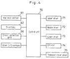
- the copying machine body 1 includes a control unit 70 shown in Fig. 4.
- the control unit 70 includes a microcomputer system including a CPU, a RAM, a ROM, several drivers, and several 1/0 portions.
- Upper driver 71 is connected to the control unit 70 for driving the feeding roller 18 and the separating roller pair 22 for the feeding cassette 13, a middle driver 72 for the feeding cassette 14, a lower driver 73 for the feeding cassette 15, and a driver 74 for the large feeding cassette 16.
- the transport roller driver 75 is in contact with, for the purpose of driving, the feed rollers within the vertical transport path 26.
- the control unit 70 connected are the key input portion 61 and the display 62 of the operation panel 60, the sheet detection gate 56, and other I/O portions.
- step S1 It is determined at step S1 whether it is time to start sheet supply from the feeding cassette storing sheets of predetermined size or not. Then, it is determined at step S2 whether a predetermined time T1 has elapsed from the start of sheet supply or not.
- the predetermined time T1 is a time sufficient for the sheet to be transported from the feeding cassette to the guiding rollers 27 disposed downstream of the feeding cassette in the sheet-transporting direction.
- step S1 a variable n showing the number of feeding operations is set to "1".
- step S4 a timer for counting the predetermined time T1 is started.
- step S5 the clutch 54 for feeding the sheet from the specified cassette is turned on, whereupon the feeding roller 52 and the sorting roller pair 53 are driven. Then, the program proceeds from step S5 to step S2.
- step S6 the clutch 54 is turned off, whereupon the feeding operation is once halted. Then, it is determined at step S7 whether the sheet detection gate 56 has been engaged or not. More specifically, it is determined whether the sheet actually reaches the guiding roller pair 27 or not. Wherein it is determined that the gate 56 is engaged, the program proceeds to step S8. At step S8, the sheet is transported toward the image forming unit 5 by the guiding roller pair and other elements.
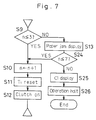
- step S7 determines whether the gate 56 has not been engaged at step S7.
- step S9 determines whether the variable n is equal to or less than "3" or not. Wherein it is determined that the variable n is "3" or less, the program proceeds from step S9 to step S10.
- step S10 the variable n is incremented.
- step S11 the timer for counting the predetermined time T1 is reset and started again.
- step S12 the clutch 54 is turned on again, whereupon sheet-feeding operation is started again in a case of feeding defect (a case where the sheet does not reach the guiding rollers 27 after the predetermined time T1 has elapsed from the start of sheet supply).
- step S9 the program proceeds from step S9 to step S13.
- step S13 the LED indicating the paper jam and time to replace a feeding roller in the LED display 66 are lit.
- step S14 the operation of the copying machine body 1 is halted and the program is completed.
- the feeding operation is performed three times when the feeding defect is generated and the paper jam is not displayed until the operation is performed four times.
- the machine is not unnecessarily halted even when the feeding defect is generated once, reducing the number of halting operation of the machine.
- Fig. 6 shows an embodiment for detecting a life of the feeding roller. Since this embodiment is the same as the embodiment I except for a process which will be described later, a description other than that process is omitted. In addition, in Fig. 6, the same references are allotted to the same steps as in Fig. 5.
- variable n is set to "1" at step S3, and then the program proceeds to step S3a.
- a variable k is incremented, and then the program proceeds to step S4.
- the variable k is for counting the number of operations of the clutch 54, which is set to "0" at initialization.
- step S31 It is determined at step S31 whether the variable k is equal to or more than 1500 or not (that is, whether the clutch 54 is operated 1500 times or more, or not). Wherein the variable k is less than 1500, the program proceeds to succeeding general step. Alternatively, wherein the variable k is 1500 or more, the program proceeds to step S32.
- step S32 It is determined at step S32 whether the variable p is equal to or more than 1000 or not (that is, whether the gate 56 was engaged 1000 times or more, or not) . Wherein the variable p is 1000 or more, it is determined that the feeding roller 18 can be still used, and then the program proceeds to step S33. At step S33, the variable p and the variable k are reset to "0". Wherein the variable p is less than 1000, it is determined that the feeding roller 18 should be replaced, and then the program proceeds to step S34, in which "replace roller" is displayed in the LED display 66. Then, the program proceeds to step S33, in which the variables p and k are initialized.
- the actual number of supplied sheets (the number of times the gate 56 has been engaged by the sheets) is detected, and this number is compared to the number of operations of the clutch 54. Then, when the number of supplied sheets is considerably less than the number of the feeding operations, it is determined that the feeding roller is worn out and should be replaced.
Landscapes
- Physics & Mathematics (AREA)
- General Physics & Mathematics (AREA)
- Controlling Sheets Or Webs (AREA)
- Sheets, Magazines, And Separation Thereof (AREA)
- Paper Feeding For Electrophotography (AREA)
Applications Claiming Priority (2)
| Application Number | Priority Date | Filing Date | Title |
|---|---|---|---|
| JP310209/92 | 1992-11-19 | ||
| JP31020992A JP3173626B2 (ja) | 1992-11-19 | 1992-11-19 | 画像形成装置用給紙装置 |
Publications (1)
| Publication Number | Publication Date |
|---|---|
| EP0598416A1 true EP0598416A1 (fr) | 1994-05-25 |
Family
ID=18002510
Family Applications (1)
| Application Number | Title | Priority Date | Filing Date |
|---|---|---|---|
| EP93118683A Withdrawn EP0598416A1 (fr) | 1992-11-19 | 1993-11-19 | Appareil pour alimentation en feuilles pour appareil de formation d'images |
Country Status (3)
| Country | Link |
|---|---|
| US (1) | US5395106A (fr) |
| EP (1) | EP0598416A1 (fr) |
| JP (1) | JP3173626B2 (fr) |
Cited By (1)
| Publication number | Priority date | Publication date | Assignee | Title |
|---|---|---|---|---|
| BE1009854A3 (fr) * | 1995-05-12 | 1997-10-07 | Bourg C P Sa | Distributeur d'objets plats et flexibles. |
Families Citing this family (10)
| Publication number | Priority date | Publication date | Assignee | Title |
|---|---|---|---|---|
| US5490667A (en) * | 1993-08-31 | 1996-02-13 | Minolta Co., Ltd. | Sheet transportation apparatus carrying out error determination considering switching of sheet transportation path |
| JP3392998B2 (ja) * | 1995-12-25 | 2003-03-31 | 日本碍子株式会社 | シート材の加工装置 |
| JPH11255381A (ja) * | 1998-03-09 | 1999-09-21 | Japan Business Computer Co Ltd | 光学式読取装置の用紙位置決め機構及び用紙位置決め 方法 |
| US6193426B1 (en) * | 1999-09-29 | 2001-02-27 | Hewlett-Packard Company | Method of determining optimum time for replacing the media feed roller of a printing device |
| DE10016107A1 (de) * | 2000-03-31 | 2001-10-04 | Heidelberger Druckmasch Ag | Verfahren und Vorrichtung zur Verhinderung von Grenzwertüberschreitungen bei Bogendruckmaschinen |
| JP4486989B2 (ja) | 2007-10-12 | 2010-06-23 | シャープ株式会社 | 給紙装置、これを備えた画像形成装置、給紙方法、給紙プログラム、及びこのプログラムを記録したコンピュータ読取可能な記録媒体 |
| CN102131717A (zh) * | 2008-06-23 | 2011-07-20 | D·拉普科 | 用于拾取、保持和分配物体的设备 |
| JP5865331B2 (ja) * | 2013-10-31 | 2016-02-17 | 京セラドキュメントソリューションズ株式会社 | 画像形成装置 |
| JP5987023B2 (ja) | 2014-06-20 | 2016-09-06 | 京セラドキュメントソリューションズ株式会社 | 用紙供給装置、これを備えた原稿搬送装置及び画像形成装置 |
| JP6790627B2 (ja) * | 2016-09-09 | 2020-11-25 | コニカミノルタ株式会社 | 給紙装置及び画像形成装置 |
Citations (2)
| Publication number | Priority date | Publication date | Assignee | Title |
|---|---|---|---|---|
| US4589765A (en) * | 1985-05-22 | 1986-05-20 | Xerox Corporation | Sheet feeder control for reproduction machines |
| US4860052A (en) * | 1986-09-13 | 1989-08-22 | Minolta Camera Kabushiki Kaisha | Copying apparatus with use frequency cancellation control |
Family Cites Families (10)
| Publication number | Priority date | Publication date | Assignee | Title |
|---|---|---|---|---|
| JPS5854435Y2 (ja) * | 1980-10-31 | 1983-12-12 | 富士通株式会社 | シ−ト状媒体の繰出装置 |
| JPS58219571A (ja) * | 1982-06-15 | 1983-12-21 | Canon Inc | 複写機 |
| JPH0238229A (ja) * | 1988-07-27 | 1990-02-07 | Nec Corp | 給紙装置 |
| US4985729A (en) * | 1988-09-12 | 1991-01-15 | Xerox Corporation | Control system for reproduction machines providing an extended almost jam interval and shutdown delay |
| JPH03272947A (ja) * | 1990-03-22 | 1991-12-04 | Koufu Nippon Denki Kk | 紙葉類搬送装置 |
| JPH03284961A (ja) * | 1990-03-31 | 1991-12-16 | Nec Corp | 印刷装置 |
| JPH0432442A (ja) * | 1990-05-25 | 1992-02-04 | Hitachi Koki Co Ltd | 印刷装置 |
| JPH0442165A (ja) * | 1990-06-08 | 1992-02-12 | Toshiba Corp | 画像形成装置 |
| JPH0451445U (fr) * | 1990-09-06 | 1992-04-30 | ||
| JPH0543620A (ja) * | 1991-08-15 | 1993-02-23 | Nippon Petrochem Co Ltd | 高圧法ポリエチレン製造装置用ガス放出装置 |
-
1992
- 1992-11-19 JP JP31020992A patent/JP3173626B2/ja not_active Expired - Fee Related
-
1993
- 1993-11-12 US US08/151,117 patent/US5395106A/en not_active Expired - Lifetime
- 1993-11-19 EP EP93118683A patent/EP0598416A1/fr not_active Withdrawn
Patent Citations (2)
| Publication number | Priority date | Publication date | Assignee | Title |
|---|---|---|---|---|
| US4589765A (en) * | 1985-05-22 | 1986-05-20 | Xerox Corporation | Sheet feeder control for reproduction machines |
| US4860052A (en) * | 1986-09-13 | 1989-08-22 | Minolta Camera Kabushiki Kaisha | Copying apparatus with use frequency cancellation control |
Non-Patent Citations (1)
| Title |
|---|
| BESSETTE: "Designing Reliable Paper-Handling Systems", MACHINE DESIGN, vol. 57, no. 10, 9 May 1985 (1985-05-09), CLEVELAND US, pages 54 - 58 * |
Cited By (1)
| Publication number | Priority date | Publication date | Assignee | Title |
|---|---|---|---|---|
| BE1009854A3 (fr) * | 1995-05-12 | 1997-10-07 | Bourg C P Sa | Distributeur d'objets plats et flexibles. |
Also Published As
| Publication number | Publication date |
|---|---|
| JPH06156815A (ja) | 1994-06-03 |
| US5395106A (en) | 1995-03-07 |
| JP3173626B2 (ja) | 2001-06-04 |
Similar Documents
| Publication | Publication Date | Title |
|---|---|---|
| US5347350A (en) | Sheet feeder | |
| US4925177A (en) | Automatic paper feeder | |
| EP0743566A2 (fr) | Appareil d'entraînement de feuilles et appareil de formation d'images | |
| US5395106A (en) | Sheet forwarding apparatus for determining causes of feeding defects | |
| JPS63106250A (ja) | 像形成機 | |
| US5761567A (en) | Image forming apparatus with jam detection for permitting completion of a copy operation | |
| US6643474B2 (en) | Abnormality displaying apparatus for use in image forming apparatus | |
| US5539499A (en) | Image forming apparatus with improved warning indication for plurality of troubles | |
| JP4244042B2 (ja) | シート搬送制御方法及び画像形成装置 | |
| JP3984976B2 (ja) | シート搬送装置および画像形成装置 | |
| JPH08245062A (ja) | 記録装置における記録紙の取り出し方法とその装置 | |
| EP0270037B1 (fr) | Dispositif d'affichage pour appareil de formation d'image | |
| US5257082A (en) | Copier with automatic insert feed having an interrupt function | |
| JPH08301482A (ja) | 複写機の用紙搬送制御装置 | |
| US6137968A (en) | Image forming apparatus | |
| JP3213106B2 (ja) | 画像形成装置 | |
| JP2934044B2 (ja) | 画像形成装置 | |
| JP2734752B2 (ja) | ジャム処理機能付画像形成装置 | |
| JP2749184B2 (ja) | シート搬送装置のジャム回数検出装置 | |
| US5153641A (en) | Control circuit for designating paper feed opening to which optimum kind of copy sheet is to be set in image forming apparatus | |
| US4879574A (en) | Copying apparatus having an automatic document feeder and at least two operation modes | |
| JP3276016B2 (ja) | 複写機のマルチジョブ制御装置 | |
| JPS62275947A (ja) | 複写機 | |
| JP2570751B2 (ja) | 作像装置 | |
| JP2692750B2 (ja) | 画像形成装置の排紙装置 |
Legal Events
| Date | Code | Title | Description |
|---|---|---|---|
| PUAI | Public reference made under article 153(3) epc to a published international application that has entered the european phase |
Free format text: ORIGINAL CODE: 0009012 |
|
| AK | Designated contracting states |
Kind code of ref document: A1 Designated state(s): DE FR GB IT |
|
| 17P | Request for examination filed |
Effective date: 19940826 |
|
| 17Q | First examination report despatched |
Effective date: 19960209 |
|
| STAA | Information on the status of an ep patent application or granted ep patent |
Free format text: STATUS: THE APPLICATION IS DEEMED TO BE WITHDRAWN |
|
| 18D | Application deemed to be withdrawn |
Effective date: 19960620 |