EP0598687A1 - Krawattenhalter - Google Patents
Krawattenhalter Download PDFInfo
- Publication number
- EP0598687A1 EP0598687A1 EP93830456A EP93830456A EP0598687A1 EP 0598687 A1 EP0598687 A1 EP 0598687A1 EP 93830456 A EP93830456 A EP 93830456A EP 93830456 A EP93830456 A EP 93830456A EP 0598687 A1 EP0598687 A1 EP 0598687A1
- Authority
- EP
- European Patent Office
- Prior art keywords
- box
- hooks
- bar
- driving bar
- support frame
- Prior art date
- Legal status (The legal status is an assumption and is not a legal conclusion. Google has not performed a legal analysis and makes no representation as to the accuracy of the status listed.)
- Withdrawn
Links
- 230000007246 mechanism Effects 0.000 abstract description 3
- 238000004519 manufacturing process Methods 0.000 description 3
- 238000010276 construction Methods 0.000 description 2
- 239000002184 metal Substances 0.000 description 2
- 229920003023 plastic Polymers 0.000 description 2
- 239000004033 plastic Substances 0.000 description 2
- 230000000750 progressive effect Effects 0.000 description 2
- 229910000831 Steel Inorganic materials 0.000 description 1
- 238000006073 displacement reaction Methods 0.000 description 1
- 229910001234 light alloy Inorganic materials 0.000 description 1
- 239000000463 material Substances 0.000 description 1
- 239000010959 steel Substances 0.000 description 1
Images




Classifications
-
- A—HUMAN NECESSITIES
- A47—FURNITURE; DOMESTIC ARTICLES OR APPLIANCES; COFFEE MILLS; SPICE MILLS; SUCTION CLEANERS IN GENERAL
- A47G—HOUSEHOLD OR TABLE EQUIPMENT
- A47G25/00—Household implements used in connection with wearing apparel; Dress, hat or umbrella holders
- A47G25/74—Necktie holders ; Belt holders
- A47G25/746—Necktie holders ; Belt holders mounted on wall, ceiling or the like
Definitions
- the present invention relates to tie-holder devices, of the type comprising: a support frame, a plurality of tie-holding hooks rotatably mounted on the support frame and having respective crank shaped ends associated with a driving bar which is slidably mounted with respect to the support frame between a first position, in which the hooks are substantially parallel to said driving bar and a second position in which the hooks are substantially orthogonal to said driving bar.
- tie-holders of the type specified above which have been provided up to date are of a relatively complicated and costly construction, are not completely reliable and safe in use and are not always aesthetically appealing.
- the present invention provides a tie-holder device of the above indicated type, whose main feature lies in that said support frame comprises an elongated box-like body which rotatably supports the tie-holding hooks and encapsulates the crank-shaped ends of the hooks and the driving bar, said device further comprising means for holding the driving bar in any of its two end positions, said means being also encapsulated within said elongated box-like body.
- the structure of the device according to the invention may be provided in various materials, such as plastics, light alloy, steel sheet metal.
- the main advantage of the invention lies in the provision of said box-like support body which acts on one hand as a support frame and on the other hand as a protecting cover for the mechanisms, having also an aesthetical function.
- the device according to the invention further comprises spring means also encapsulated within the box-like body and tending to push the driving bar towards its second position.
- the device further comprises disengageable latch means for holding the driving bar in its first position against the action of said spring means.
- said spring means tending to push the driving bar towards its second position are not provided, and the means for holding the driving bar in any of its two end positions are formed by a U-shaped spring able to snap-engage a nose portion provided at each end of the driving bar.
- the driving bar is provided adjacent to each of its ends with an operating lever projecting through a slot of the box-like body.
- the driving bar is provided only at one end with a lever projecting through a slot of the box-like body, which is used to engage said latch means against the action of said spring means, the box-like body further bearing a push-button able to release the latch means so as to cause the automatic displacement of the driving bar towards its second position.
- the device according to the invention is characterised by a great simplicity of manufacture and assembling and, at the same time, due to the use of a support frame in form of a box-like body which protects all the mechanisms, it is sure and reliable in use and may be provided with shapes which are aesthetically appealing.
- numeral 1 generally designates a tie-holder device according to the invention.
- Device 1 comprises a support frame 2 formed by a base 3 in form of an elongated parallelepiped on which there is mounted, by means of a pair of hollow rivets 27, 28, a box-like body 4.
- Frame 2 on its turn is fixed to a support element 30, such as a door of a piece of furniture, by means of screws 34, 35 respectively received within rivets 27, 28.
- Device 1 further comprises a plurality of hooks 5 for holding ties or the like, indicated by 29 in figure 1, the hooks being rotatably mounted on frame 2.
- hooks 5 are pivoted on opposite sides, respectively upper side 4a and lower side 4b, of the box-like body 4, so as to form two parallel superimposed rows offset from each other.
- Each hook 5 comprises an arm 6, for holding a tie or the like, an intermediate portion 7, forming an angle approximately of 90 degrees with arm 6, and a free end 9, substantially crank-shaped.
- arm 6 comprises two portions 6a, 6b forming an angle ⁇ of a predetermined value therebetween, comprised between 120 degrees and 140 degrees and preferably of 135 degrees.
- Each hook 5 is also pivoted to the box-like body 4 due to the portion 7 received in respective seats 8a, 8b, semicircular in shape, formed on sides 4a, 4b of body 4, each hook 5 being associated with a bar slidably mounted within the box-like body 4.
- the latter is provided at a first end 10a with a operating bush-button 12 which on its turn is slidably mounted in a respective seat 13 formed in the box-like body 4.
- bar 10 is subject to respective spring means 14, such as a helical spring, mounted on a spring guide 15 and received in a respective conjugated seat 16 axially formed within bar 10.
- spring means 14 such as a helical spring
- Said means 17 comprises a latch device 18 including a button 19 pivoted to the box-like body 4 by means of a first arm 20 and cooperating with bar 10 by means of a second arm 21.
- arm 21 is provided with a stop tooth 22 for removably engaging tooth 31 formed in an end 10b of bar 10.
- arm 20 has a U-shaped portion comprising two wings 20a, 20b between which there is defined a seat for receiving the hollow rivet 28.
- Button 19 is also subject to the action of respective spring means 23, such as a helical spring, received in a respective conjugated seat 24 formed in the button itself, button 19 being slidably mounted in an aperture 25 formed in the box-like body 4. From this aperture 25, button 19 projects for a predetermined length, defined by the abutment between a stop surface 26 formed on first arm 20 and the edge of aperture 25.
- spring means 23 such as a helical spring
- portions 6a of arms 6 are adjacent to frame 2 and hold ties 29 lying thereon.
- tooth 31 formed at the end 10b of bar 10 disengages from stop tooth 22 and the bar is free to move inside the box-like body 4 and is pushed by spring means 14 in a second position defined by abutment thereof against the body of button 19.
- arms 6 rotate towards their opened position by an angle of a predetermined amplitude, approximately of 90 degrees, and reach the position illustrated in figure 4.
- portions 6a of arms 6 extend substantially orthogonally to the box-like body 4 allowing one or more ties to be picked up or stored.
- the above described device has an operation which is safe and reliable with the time.
- the good operation of the device is particularly ensured by the box-like body 4 which fulfils the function of supporting, guiding and protecting all the moving parts.
- the device has the further advantage of an extremely easy assembling which can be carried out by means of the hollow rivets 27, 28 which connect the box-like body 4 to the base 3.
- the same hollow rivets 27, 28 allow also the device 1 to be mounted on the support surface 30, such as the door of a piece of furniture, by means of screws 34, 35.
- the reduced size of device 1 allows two or more box-like bodies to be mounted on a same base 3, thus varying at will the number of available hooks.
- Hooks 5 and the other parts of device 1 can be made of metal or plastics with automatic apparatus and with a minimum number of operators, to the advantage of the production costs.
- reference numeral 1 generally designates the tie-holder device.
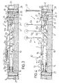
- Device 1 comprises a support frame 2 formed by a base 3 on which there is mounted a box-like body 4 by means of a pair of hollow rivets 14, 15, received in respective tubular seats 27, 28.
- Frame 2 on its turn is fixed to a support element 16, such as a door of a piece of furniture, by means of screws 17, 18 respectively received within rivets 14, 15.
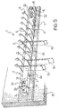
- Device 1 further comprises a plurality of hooks 5 for supporting ties or the like indicated by 19 in figure 5, the hooks being rotatably mounted on frame 2.
- hooks 5 are pivoted on opposite sides, respectively upper side 4a and lower side 4b, of the box-like body 4 so as to form two parallel superimposed rows offset from each other.
- Each hook 5 comprises an arm 6, for supporting a tie or the like, an intermediate portion 7, forming with arm 6 an angle approximately of 90 degrees and a free end 9, substantially crank-shaped.
- the arm 6 comprises two portions 6a, 6b forming an angle ⁇ therebetween of a predetermined value, comprised between 120 degrees and 140 degrees and preferably of 135 degrees.
- Each hook 5 is also pivoted to the box-like body 4 due to the portion 7 received in respective conjugated seats 8a, 8b semicircular in shape on sides 4a, 4b of body 4 and is associated with a bar 10 slidably mounted within the box-like body 4.
- driving means generally designated by 20, including, in a preferred form, a pair of levers 29, 30 formed in one piece with bar 10.
- Levers 29, 30 are substantially S-shaped for a convenient manual operation and are movably guided in respective apertures 31, 32 which are slot-shaped, formed in the box-like body 4, between opposite positions defined by the abutment against opposite edges of such slots.
- device 1 further comprises a pair of springs 33, 34 substantially U-shaped, respectively associated with ends 10a, 10b of bar 10 and generally constituting means for removably holding bar 10 in opposite positions in which hooks 5 are respectively opened and closed.
- Springs 33, 34 mounted on opposite sides of tubular seats 27, 28, are provided with planar wings indicated with numerals 35-38, cooperating by snap engagement with a pair of stop portions 25, 26 formed at ends 10a, 10b of bar 10 adjacent to levers 29, 30.
- each of said stop portions 25, 26 comprises two teeth longitudinally formed on opposite sides of bar 10 and having tapered sides, whereas wings 35-38 of the springs are provided with projections substantially semicircular in shape, cooperating with said teeth.
- stop portion 25 and spring 33 are absolutely similar.
- levers 29 and 30 When one wishes to open hooks 5, it is sufficient to act on levers 29 and 30 so as to bring bar 10 in the position illustrated in figures 5, 6 and 7.
- levers 29, 30 abut against the edges of slots 31, 32, the stop portion 25 is engaged between wings 35, 36 of spring 33 and the stop portion 26 escapes from spring 34.
- arms 6 rotate towards their opened condition by an angle of a predetermined amplitude, approximately of 90 degrees, so as to reach an operative condition in which their portions 6a extend substantially orthogonally to the box-like body 4 thus allowing one or more ties to be picked up or stored.
- hooks 5 By acting on levers 29, 30, hooks 5 can then be brought back in their closed condition by moving rearwardly bar 10 so as to bring it back to the start condition illustrated in figures 5 and 6.
- the tie holder device of the present invention has a safe and reliable operation with a progressive and smooth movement of hooks 5 and bar 10.
- the good operation of the device is particularly ensured by the box-like body 4 which fulfils the function of supporting, guiding and protecting all the moving parts. Also in this case, furthermore, the assembling of the hooks is simple and quick and is absolutely similar to what has been described with reference to figures 1-4. Also all the remaining advantages which have been cited above with reference to the first embodiment of the invention are also achieved by the embodiment shown in figures 5-10.
Landscapes
- Clamps And Clips (AREA)
Applications Claiming Priority (4)
| Application Number | Priority Date | Filing Date | Title |
|---|---|---|---|
| IT000995 IT226994Y1 (it) | 1992-11-17 | 1992-11-17 | Dispositivo portacravatte avente ganci di supporto manualmente posizionabili in apertura ed in chiusura |
| ITMI920995U | 1992-11-17 | ||
| ITMI922626 | 1992-11-17 | ||
| IT002626 IT1264779B (it) | 1992-11-17 | 1992-11-17 | Dispositivo portacravatte a ganci mobili |
Publications (1)
| Publication Number | Publication Date |
|---|---|
| EP0598687A1 true EP0598687A1 (de) | 1994-05-25 |
Family
ID=26330867
Family Applications (1)
| Application Number | Title | Priority Date | Filing Date |
|---|---|---|---|
| EP93830456A Withdrawn EP0598687A1 (de) | 1992-11-17 | 1993-11-17 | Krawattenhalter |
Country Status (2)
| Country | Link |
|---|---|
| US (1) | US5425463A (de) |
| EP (1) | EP0598687A1 (de) |
Cited By (1)
| Publication number | Priority date | Publication date | Assignee | Title |
|---|---|---|---|---|
| GB2309891A (en) * | 1996-02-12 | 1997-08-13 | Y & H Industrial Ltd | Necktie hanger |
Families Citing this family (13)
| Publication number | Priority date | Publication date | Assignee | Title |
|---|---|---|---|---|
| US6679392B1 (en) | 2002-01-22 | 2004-01-20 | Sidelines, Inc. | Sliding hanger assembly |
| US6871749B2 (en) * | 2003-04-11 | 2005-03-29 | Dillingham Products Company, Llc | Extendable/retractable valet rack |
| US7455186B2 (en) * | 2005-05-24 | 2008-11-25 | Gregory David M | Tie rack |
| US7600645B2 (en) * | 2005-05-24 | 2009-10-13 | Gregory David M | Tie rack |
| USD648141S1 (en) * | 2008-06-03 | 2011-11-08 | Rev-A-Shelf Company, Llc | Valet rod |
| US7681851B1 (en) | 2008-07-14 | 2010-03-23 | Osterholt Lana M | Retractable hook device |
| US8028844B2 (en) * | 2008-11-20 | 2011-10-04 | Costa Charles A | Sliding closet rack |
| TWM468241U (zh) * | 2013-03-27 | 2013-12-21 | Ulike Corp | 承載裝置 |
| US9717358B2 (en) * | 2014-10-31 | 2017-08-01 | Kevin R. Davis | Belt and necktie rack |
| USD775477S1 (en) * | 2015-11-27 | 2017-01-03 | Hardware Resources, Inc. | Tie rack |
| USD775476S1 (en) * | 2015-11-27 | 2017-01-03 | Hardware Resources, Inc. | Belt rack |
| USD852518S1 (en) * | 2019-01-16 | 2019-07-02 | Hip Innovations, Llc | Tie hanger |
| US11259655B1 (en) * | 2021-01-11 | 2022-03-01 | Qwinassau Humphries | Wall mountable wig rack |
Citations (8)
| Publication number | Priority date | Publication date | Assignee | Title |
|---|---|---|---|---|
| BE409420A (de) * | ||||
| US1913215A (en) * | 1931-05-22 | 1933-06-06 | Meyer D Schwartz | Holder for neckties, etc. |
| US2334740A (en) * | 1942-03-02 | 1943-11-23 | Miguel B Acosta | Article holder |
| US2499159A (en) * | 1946-05-15 | 1950-02-28 | Pestyner Philip | Necktie rack |
| US2575111A (en) * | 1950-06-10 | 1951-11-13 | Kruger Cyril | Necktie rack |
| US2575112A (en) * | 1950-08-02 | 1951-11-13 | Kruger Cyril | Necktie rack |
| US2603359A (en) * | 1952-07-15 | Necktie rack | ||
| US4569450A (en) * | 1983-08-24 | 1986-02-11 | Dillingham Richard F | Necktie storage rack with folding hanger members |
Family Cites Families (5)
| Publication number | Priority date | Publication date | Assignee | Title |
|---|---|---|---|---|
| US2061156A (en) * | 1935-07-03 | 1936-11-17 | Harry G Humphrey | Dress display rack |
| US2515293A (en) * | 1946-12-12 | 1950-07-18 | Ramon Montalvo | Utility rack |
| US2582127A (en) * | 1949-03-12 | 1952-01-08 | Alfred J Hort | Necktie rack |
| US2609935A (en) * | 1950-07-20 | 1952-09-09 | Kruger Cyril | Necktie rack |
| US2724510A (en) * | 1953-03-19 | 1955-11-22 | Williams Mfg Co Inc | Tie rack |
-
1993
- 1993-11-17 US US08/153,040 patent/US5425463A/en not_active Expired - Fee Related
- 1993-11-17 EP EP93830456A patent/EP0598687A1/de not_active Withdrawn
Patent Citations (8)
| Publication number | Priority date | Publication date | Assignee | Title |
|---|---|---|---|---|
| BE409420A (de) * | ||||
| US2603359A (en) * | 1952-07-15 | Necktie rack | ||
| US1913215A (en) * | 1931-05-22 | 1933-06-06 | Meyer D Schwartz | Holder for neckties, etc. |
| US2334740A (en) * | 1942-03-02 | 1943-11-23 | Miguel B Acosta | Article holder |
| US2499159A (en) * | 1946-05-15 | 1950-02-28 | Pestyner Philip | Necktie rack |
| US2575111A (en) * | 1950-06-10 | 1951-11-13 | Kruger Cyril | Necktie rack |
| US2575112A (en) * | 1950-08-02 | 1951-11-13 | Kruger Cyril | Necktie rack |
| US4569450A (en) * | 1983-08-24 | 1986-02-11 | Dillingham Richard F | Necktie storage rack with folding hanger members |
Cited By (2)
| Publication number | Priority date | Publication date | Assignee | Title |
|---|---|---|---|---|
| GB2309891A (en) * | 1996-02-12 | 1997-08-13 | Y & H Industrial Ltd | Necktie hanger |
| GB2309891B (en) * | 1996-02-12 | 1998-04-08 | Lee Tack Plastic & Metal Manuf | Necktie hanger |
Also Published As
| Publication number | Publication date |
|---|---|
| US5425463A (en) | 1995-06-20 |
Similar Documents
| Publication | Publication Date | Title |
|---|---|---|
| US5425463A (en) | Tie-holder device | |
| US4156311A (en) | Shear with resilient latch | |
| EP2898162B1 (de) | Komplett eingelassener türgriff mit einem schloss | |
| DE2812979C2 (de) | Kraftbetriebenes Klammergerät | |
| RU2763718C2 (ru) | Складная шарнирная конструкция, в частности, для поддержки сиденья или опорной поверхности | |
| US4961239A (en) | Fixed yet pivotable knife or tool | |
| US5241728A (en) | Resilient clip | |
| JPH11264270A (ja) | 引戸の構造及び引戸閉塞装置 | |
| EP0221596A1 (de) | Gewichtsausgleichs- und Sicherheitsvorrichtung eines Vertikalschrankdeckels | |
| US4757942A (en) | Double door mailbox | |
| US4407039A (en) | Dust mop handle attachment device | |
| CN113876071A (zh) | 鞋套机装置 | |
| DE69200602D1 (de) | Sicherheitsvorrichtung für Schachtklappdeckel. | |
| US2237731A (en) | Clasp | |
| US3292250A (en) | Spring expander | |
| KR200180777Y1 (ko) | 회전식 가이드 스토퍼 | |
| JPS6214310Y2 (de) | ||
| JPS6124423Y2 (de) | ||
| US2492254A (en) | He houder construction | |
| JPH0523727Y2 (de) | ||
| KR810000244Y1 (ko) | 전 기 빗 장 | |
| US2596287A (en) | Hat holder | |
| GB2131077A (en) | Window latching devices | |
| EP0808981A2 (de) | Einrichtung für die Steuerung des Öffnungs- und Schliessvorganges von Kraftfahrzeugtüren | |
| KR890004059Y1 (ko) | 문짝용 핸들장치 |
Legal Events
| Date | Code | Title | Description |
|---|---|---|---|
| PUAI | Public reference made under article 153(3) epc to a published international application that has entered the european phase |
Free format text: ORIGINAL CODE: 0009012 |
|
| AK | Designated contracting states |
Kind code of ref document: A1 Designated state(s): DE ES FR GB NL |
|
| 17P | Request for examination filed |
Effective date: 19940902 |
|
| GRAG | Despatch of communication of intention to grant |
Free format text: ORIGINAL CODE: EPIDOS AGRA |
|
| GRAG | Despatch of communication of intention to grant |
Free format text: ORIGINAL CODE: EPIDOS AGRA |
|
| GRAH | Despatch of communication of intention to grant a patent |
Free format text: ORIGINAL CODE: EPIDOS IGRA |
|
| 17Q | First examination report despatched |
Effective date: 19970821 |
|
| STAA | Information on the status of an ep patent application or granted ep patent |
Free format text: STATUS: THE APPLICATION IS DEEMED TO BE WITHDRAWN |
|
| 18D | Application deemed to be withdrawn |
Effective date: 19971223 |