EP0598811B1 - Geschlechtloser elektrischer verbinder - Google Patents
Geschlechtloser elektrischer verbinder Download PDFInfo
- Publication number
- EP0598811B1 EP0598811B1 EP92917751A EP92917751A EP0598811B1 EP 0598811 B1 EP0598811 B1 EP 0598811B1 EP 92917751 A EP92917751 A EP 92917751A EP 92917751 A EP92917751 A EP 92917751A EP 0598811 B1 EP0598811 B1 EP 0598811B1
- Authority
- EP
- European Patent Office
- Prior art keywords
- connector
- male
- female
- block
- pin
- Prior art date
- Legal status (The legal status is an assumption and is not a legal conclusion. Google has not performed a legal analysis and makes no representation as to the accuracy of the status listed.)
- Expired - Lifetime
Links
Images

Classifications
-
- H—ELECTRICITY
- H01—ELECTRIC ELEMENTS
- H01R—ELECTRICALLY-CONDUCTIVE CONNECTIONS; STRUCTURAL ASSOCIATIONS OF A PLURALITY OF MUTUALLY-INSULATED ELECTRICAL CONNECTING ELEMENTS; COUPLING DEVICES; CURRENT COLLECTORS
- H01R24/00—Two-part coupling devices, or either of their cooperating parts, characterised by their overall structure
- H01R24/84—Hermaphroditic coupling devices
-
- H—ELECTRICITY
- H01—ELECTRIC ELEMENTS
- H01R—ELECTRICALLY-CONDUCTIVE CONNECTIONS; STRUCTURAL ASSOCIATIONS OF A PLURALITY OF MUTUALLY-INSULATED ELECTRICAL CONNECTING ELEMENTS; COUPLING DEVICES; CURRENT COLLECTORS
- H01R13/00—Details of coupling devices of the kinds covered by groups H01R12/70 or H01R24/00 - H01R33/00
- H01R13/62—Means for facilitating engagement or disengagement of coupling parts or for holding them in engagement
- H01R13/627—Snap or like fastening
-
- Y—GENERAL TAGGING OF NEW TECHNOLOGICAL DEVELOPMENTS; GENERAL TAGGING OF CROSS-SECTIONAL TECHNOLOGIES SPANNING OVER SEVERAL SECTIONS OF THE IPC; TECHNICAL SUBJECTS COVERED BY FORMER USPC CROSS-REFERENCE ART COLLECTIONS [XRACs] AND DIGESTS
- Y10—TECHNICAL SUBJECTS COVERED BY FORMER USPC
- Y10S—TECHNICAL SUBJECTS COVERED BY FORMER USPC CROSS-REFERENCE ART COLLECTIONS [XRACs] AND DIGESTS
- Y10S439/00—Electrical connectors
- Y10S439/949—Junction box with busbar for plug-socket type interconnection with receptacle
Definitions
- the present invention relates to a hermaphroditic electrical connector with at least two poles, the connector comprising at least one female contact piece provided with a socket at a front end of the connector, at least one male contact piece provided with a pin at said connector. front end, and an elongated insulating housing which laterally surrounds the contact parts and comprises, at said front end, male and female forms comprising at least one male tubular protection part and at least one female tubular protection part, said tubular parts forming an integral part of the housing and laterally surrounding the socket and the pin respectively, said front end of the connector being arranged so as to be able to be connected to the front end of an identical connector so that said pin and said male tubular part of each connector are '' fit longitudinally respectively in said socket and l adite female tubular part of the other connector.
- the publication FR-A-2 501 918 describes a hermaphrodite connector of this kind, for a multi-conductor cable for the transmission of signals.
- a male electrical block, provided with several parallel pins, and a female electrical block, provided with several parallel sockets, are mounted one next to the other in a housing and have complementary shapes.
- two of these hermaphrodite connectors are connected to each other, they can be locked by means of a pivoting bracket mounted on one of them.
- Such a connection system cannot be used in an electrical supply network, in particular because it does not meet the generally imposed safety standards.
- the very low voltage supply in general 12 V
- the very low voltage supply is carried out by means of cables of all types, adjusted on the spot and connected by screw flanges whose tightening can be a source of problems and whose screws are not protected.
- the user performs the assembly himself or modifies it in order to adapt the lighting installation to changing needs. Consequently, cabling of this kind is not always made under optimum safety conditions and with the guarantee of compliance with the standards in force. If the screws are not tightened properly or loosen over time, this results in deficient contacts, voltage drops, localized heating or displacement of conductors which can lead to short circuits.
- the object of the present invention is to avoid the drawbacks mentioned above and to improve the security of the connections, thanks to a connector which can be plugged in easily and securely, ensures correct positioning of the contacts corresponding to the respective poles. , and withstands a breakout force (set at 50 N by certain standards) capable of accidentally disconnecting it.
- the use of such a connector must make it possible in particular to produce an electrical distribution network at very low voltage, at low voltage or at medium voltage, using insulated bipolar cables, provided with a hermaphrodite connector at each end.
- the invention provides a connector as defined in claim 1.
- each contact piece is traversed by a transverse orifice opposite which the housing has a lateral opening, said transverse orifices being capable of each receiving a transverse pin ensuring a mechanical and electrical connection on the connector.
- Said lateral openings of the housing can be provided with removable insulating plugs.
- the two transverse orifices have the same configuration and are arranged symmetrically, so that the connector can be connected, by means of said transverse pins, to another similar connector juxtaposed in two opposite positions, as desired.
- said male and female forms of the housing comprise two tubular protective parts, forming an integral part of the housing, laterally surrounding the pin and the socket respectively, namely a female tubular part and a tubular part.
- male arranged to fit longitudinally into the female tubular part of said similar connector.
- the male tubular part surrounds the socket and the female tubular part surrounds the pin.
- Said elastic tongue can be formed in a wall of the male tubular part, its lug being directed towards the outside, and said lateral recess being an orifice formed in a wall of the female tubular part.
- the two contact parts can be connected respectively to two insulated conductors which enter the housing by the end opposite to that where the pin and the socket are located.
- the connector according to the invention is formed by a distribution connector comprising several pairs of contact pieces, each pair being composed of a female contact piece and a male contact piece, and electrical connections connecting the female contact parts together and the male contact parts together.
- a first embodiment of such a distribution connector may comprise a separate housing for each pair of contact parts, the separate housings being juxtaposed and the pairs of contact parts being linked mechanically and electrically by means of two transverse pins engaged in said transverse orifices. At least one of the pairs of contact pieces may have an orientation opposite to that of another of said pairs.
- the distribution connector comprises a single housing containing several juxtaposed pairs of contact parts, so that one end of the connector has a row of pins and a row of sockets.
- a particular form of a connector according to the invention comprises two pairs of contact parts connected by an electrical connection comprising a fuse.
- a fuse Preferably, it comprises a pin and a socket at opposite ends of the housing and the fuse is a plug-in fuse engaged in a lateral opening of the housing, which makes it possible to interpose a fuse connector in a supply line equipped with connectors according to the invention.
- the connector 1 which is for example of the bipolar type but which could also be three-pole, comprises a housing 2 substantially rectangular, made of insulating material, which contains a female contact element 3 and a male contact element 4 , these two elements being arranged parallel in the direction of the length of the housing 2.
- the latter has openings at its two ends.
- the housing has a male tubular part 5 surrounding and protecting a contact socket 6 formed by the front end of the female contact piece 3.
- the housing has a female tubular part 7 surrounding and protecting a contact pin 8 which constitutes the front end of the male contact piece 4.
- the two tubular parts 5 and 7 have respective rectangular cross sections of different size, combined so that the male part 5 can fit together with a small clearance in the female part 7 of a connector 1 identical to this one.
- the contact pin 8 of each of the two connectors 1 will fit into the socket 6 of the other connector so as to make the electrical connection of each pole.
- a locking tab 10 is formed in a side wall of the male part 5 of the case by virtue of a U-shaped slot 11 and it has an external lug 12 having a bias at the front.
- a rectangular orifice 13 is formed in the opposite wall of the female part 7 of the housing, so that the lug 12 of an opposite connector 1 hooks onto it automatically when the two connectors are sufficiently engaged one in the other so that an electrical contact is made between their contact parts 3 and 4 by means of pins 8 and sockets 6. To ensure unlocking when it is desired to disconnect the connectors, it suffices to press on lug 12 to unhook it from orifice 13.
- each contact piece 3 and 4 is crossed by a transverse orifice 14 around which the housing has a square opening 15 which can be closed by means of a removable plug 16 of insulating material which is fixed by interlocking in the opening 15.
- the two orifices 14 are parallel and symmetrically disposed in the connector 1. They can receive transverse metal pins 17 ensuring a mechanical and electrical connection on the connector 1, as will be described later.
- the rear end of the housing 2 comprises, opposite the contact parts 3 and 4, two square openings (not shown) similar to the openings 15 and capable of being closed by similar plugs 16.
- the two rear openings are crossed by insulated conductors 18 respectively connected to the contact parts 3 and 4 in a known manner, for example by screw tightening, crimping and / or welding.
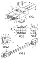
- FIG. 5 illustrates an example where the two conductors 18 together form a cord 19 equipped with a hermaphrodite connector 1 at each end. On these connectors 1, the lateral openings are closed by means of the plugs 16, so that all the conductive elements are effectively protected from the outside by insulating elements.
- Figures 2 and 3 show a distribution connector 21 composed of five simple connectors 1 which are juxtaposed and mechanically and electrically connected by means of two metal pins 17 engaged through the transverse holes 14 of the five connectors.
- the pins 17 are retained by friction in each orifice 14, for example using elastic elements such as rings or steel blades, housed inside the contact parts 3 and 4.
- the supply of all the block 21 is made by a pair of conductors 18 connected to the rear of only one of the connectors 1. All the unused openings 15 of the connectors 1 are closed by square plugs 16, so that the protection of the conductors against -visiting from the outside is assured.
- Such a connector 21 makes it possible to distribute the power in parallel to different users, in particular using cords such as that of FIG. 5, and replaces the traditional connection pads of the "domino" type, where the contact parts and the bare parts of the conductors to be connected are poorly protected from accidental contact with an external object.
- FIG. 4 shows another distribution connector 22 which is composed of three simple connectors 1 which do not all have the same orientation.
- the central connector has an orientation opposite to that of the other two, which can facilitate the connection of cords distributing electricity in different directions.
- the central connector can be connected to a power cord, while the other two are connected to two respective lamps, directly or through cords.
- FIG. 6 shows in front view a distribution connector 23 having for example three pairs of contact parts with three sockets 6 and three pins 8 arranged in the same way as in the connector 21 of Figures 2 and 3, but mounted in a housing common 24 provided with three sets of male 5 and female 7 tubular parts protecting the sockets and pins.
- One of the pairs of contact parts is connected to a pair of insulated conductors 18 and to the other two pairs inside the housing 24.
- the housing can be completely closed except for the free end of the tubular parts 5 and 7, so that no conductive element will be accessible from the outside when connectors are connected to the three pairs of contacts thereof.
- Such distribution connectors can be made with any number of pairs of contact pieces and be connected to connectors having another number of these pairs, for example the connectors 1, 21 or 22 described above.
- Figures 7 and 8 show a double connector 26 equipped with a removable fuse 27 and capable of being interposed on a supply line, between two connectors as described above.
- the connector 26 is symmetrical with respect to its median transverse plane 28; in particular each of its two ends comprises a female contact piece 33 with socket 6, a male contact piece 34 with pin 8, inside an insulating housing 29 provided with male 5 and female 7 parts as in the case of the connector 1.
- the two female parts 33 are electrically connected by a metal blade 30 disposed laterally inside a central cavity 31 of the housing, next to the fuse 27.
- This is of a known type of plug-in fuse , provided with two metal tabs 32 inserted between elastic claws 35 of each contact piece 34.
- the head 36 of the fuse remains visible outside the housing 29 to allow easy replacement of the fuse; in addition, it bears an inscription indicating the nominal intensity. Thanks to its ease of assembly and its flexibility of adaptation, such a fuse connector makes it possible to increase the operating safety of a domestic supply network, in particular in combination with distribution connectors, since it can then be protected individually against overloads the various devices supplied or the various circuits, in particular on the secondary circuits in very low voltage.
- the present invention is not limited to the exemplary embodiments and applications mentioned above, but it extends to any modification or variant obvious to a person skilled in the art.
- Connectors according to the invention can be incorporated into fixtures, for example to allow direct connection of halogen lamps, spotlights, etc.
- Connectors according to the invention can be made for any voltage, alternating or direct, including in networks powered by batteries. In order to comply with certain standards or regulations, the polarities can be identified by means of cables having appropriate colors.
Landscapes
- Details Of Connecting Devices For Male And Female Coupling (AREA)
- Connector Housings Or Holding Contact Members (AREA)
- Coupling Device And Connection With Printed Circuit (AREA)
- Addition Polymer Or Copolymer, Post-Treatments, Or Chemical Modifications (AREA)
- Measurement And Recording Of Electrical Phenomena And Electrical Characteristics Of The Living Body (AREA)
- Circuit Arrangement For Electric Light Sources In General (AREA)
Claims (11)
Applications Claiming Priority (3)
| Application Number | Priority Date | Filing Date | Title |
|---|---|---|---|
| FR9110228A FR2680285B3 (fr) | 1991-08-08 | 1991-08-08 | Systeme de cablage rapide sans outillage d'installations d'eclairage en tres basse tension. |
| FR9110228 | 1991-08-08 | ||
| PCT/FR1992/000755 WO1993003515A1 (fr) | 1991-08-08 | 1992-07-31 | Connecteur electrique hermaphrodite |
Publications (3)
| Publication Number | Publication Date |
|---|---|
| EP0598811A1 EP0598811A1 (de) | 1994-06-01 |
| EP0598811B1 true EP0598811B1 (de) | 1995-11-22 |
| EP0598811B2 EP0598811B2 (de) | 2001-11-28 |
Family
ID=9416135
Family Applications (1)
| Application Number | Title | Priority Date | Filing Date |
|---|---|---|---|
| EP92917751A Expired - Lifetime EP0598811B2 (de) | 1991-08-08 | 1992-07-31 | Geschlechtloser elektrischer verbinder |
Country Status (14)
| Country | Link |
|---|---|
| US (1) | US5487677A (de) |
| EP (1) | EP0598811B2 (de) |
| JP (1) | JPH07500213A (de) |
| CN (1) | CN1047475C (de) |
| AT (1) | ATE130705T1 (de) |
| AU (1) | AU2443492A (de) |
| CA (1) | CA2114946C (de) |
| DE (3) | DE9219034U1 (de) |
| ES (1) | ES2082492T5 (de) |
| FR (1) | FR2680285B3 (de) |
| IL (1) | IL102723A0 (de) |
| TW (1) | TW215497B (de) |
| WO (1) | WO1993003515A1 (de) |
| ZA (1) | ZA925753B (de) |
Families Citing this family (30)
| Publication number | Priority date | Publication date | Assignee | Title |
|---|---|---|---|---|
| NL1002900C2 (nl) * | 1996-04-19 | 1997-10-21 | Tl Holland | Voedingseenheid alsmede een connector ten gebruike daarmee. |
| US6007350A (en) * | 1996-09-12 | 1999-12-28 | Sumitomo Wiring Systems, Ltd. | Electrical connection box |
| US6059615A (en) * | 1997-01-31 | 2000-05-09 | Berg Technology, Inc. | Modular cable to board power connector |
| USD402628S (en) | 1997-08-21 | 1998-12-15 | The Whitaker Corporation | Electrical connector housing |
| JP2000118291A (ja) * | 1998-10-15 | 2000-04-25 | Stanley Electric Co Ltd | 車両用灯具の車体取付手段 |
| USD425860S (en) * | 1999-01-21 | 2000-05-30 | Sony Corporation | Electric connector |
| US20050196382A1 (en) * | 2002-09-13 | 2005-09-08 | Replicor, Inc. | Antiviral oligonucleotides targeting viral families |
| US6935902B1 (en) * | 2004-08-05 | 2005-08-30 | Ching Lin Chou | Coupler device for power supply facility |
| WO2008014113A1 (en) * | 2006-07-24 | 2008-01-31 | 3M Innovative Properties Company | Electrical connector and assembly |
| USD575742S1 (en) | 2006-07-24 | 2008-08-26 | 3M Innovative Properties Company | Hermaphroditic electrical connector |
| TW200910701A (en) * | 2007-08-22 | 2009-03-01 | Delta Electronics Inc | Stacked combination connector and connector assembly |
| US8383943B2 (en) | 2008-03-28 | 2013-02-26 | Greenray, Inc. | Electrical cable harness and assembly for transmitting AC electrical power |
| CN102265465B (zh) * | 2008-10-24 | 2014-10-29 | 莫列斯公司 | 具有电源和信号触头结构的连接器 |
| US20140162488A1 (en) * | 2008-10-24 | 2014-06-12 | Molex Incorporated | Circular connectors with power and signal contact pinout arrangement |
| TWD140349S1 (zh) * | 2010-03-05 | 2011-05-01 | 意力速電子工業股份有限公司 | 電氣連接器 |
| TWD140351S1 (zh) * | 2010-03-05 | 2011-05-01 | 意力速電子工業股份有限公司 | 電氣連接器 |
| JP5637015B2 (ja) * | 2011-03-04 | 2014-12-10 | 住友電装株式会社 | コネクタ |
| US8845351B2 (en) | 2011-04-08 | 2014-09-30 | Fci Americas Technology Llc | Connector housing with alignment guidance feature |
| WO2013180646A1 (en) * | 2012-06-01 | 2013-12-05 | Mea Technologies Pte. Ltd. | Two way release hermaphroditic connectors |
| US8845368B1 (en) * | 2012-08-31 | 2014-09-30 | Amazon Technologies, Inc. | Electrical connectors |
| CN104253324B (zh) * | 2013-06-25 | 2016-09-14 | 中达电通股份有限公司 | 电连接器 |
| DE102013111760B3 (de) | 2013-10-25 | 2015-04-09 | Harting Electric Gmbh & Co. Kg | Steckverbinder |
| WO2015081064A1 (en) | 2013-11-27 | 2015-06-04 | Fci Asia Pte. Ltd | Electrical power connector |
| CN204720532U (zh) * | 2015-06-18 | 2015-10-21 | 东莞鸿爱斯通信科技有限公司 | 适用于腔体滤波器的连接器 |
| CN105741894B (zh) * | 2016-03-30 | 2019-04-26 | 宁波奥崎自动化仪表设备有限公司 | 核电站用1e级反应堆堆芯温度测量设备 |
| CN106129721A (zh) * | 2016-08-31 | 2016-11-16 | 南京康尼科技实业有限公司 | 一种可对称插接的电连接器 |
| CN107819227B (zh) * | 2017-10-13 | 2020-01-14 | 许继集团有限公司 | 一种适用于继电保护测试的接线装置 |
| DE102018119547A1 (de) * | 2018-08-10 | 2020-02-13 | Volkswagen Aktiengesellschaft | Verbindungselement für Hochvolt-Batteriemodul, Anordnung mit einem solchen Verbindungselement sowie Verfahren zur Herstellung einer Verbindung zwischen einem Hochvolt-Batteriemodul und einem weiteren Element |
| CN111009773B (zh) * | 2019-12-10 | 2020-11-13 | 中国矿业大学(北京) | 电缆连接器及电缆装置 |
| CN116093656A (zh) * | 2023-03-07 | 2023-05-09 | 浙江杭可科技股份有限公司 | 一种柔性多功能快速组装式空中连接器 |
Family Cites Families (11)
| Publication number | Priority date | Publication date | Assignee | Title |
|---|---|---|---|---|
| US398769A (en) * | 1889-02-26 | Elegtric-eircuit coupler | ||
| US2384267A (en) * | 1942-04-25 | 1945-09-04 | Johan M Andersen | Electrical connector |
| GB1109919A (en) * | 1965-11-23 | 1968-04-18 | Automatic Telephone & Elect | Improvements in or relating to electrical connectors |
| US3676833A (en) * | 1970-10-30 | 1972-07-11 | Itt | Hermaphorodite electrical connector |
| US4089579A (en) * | 1976-04-01 | 1978-05-16 | Trw Inc. | Ribbon connector constructions |
| US4364626A (en) * | 1980-03-07 | 1982-12-21 | Edison Price Incorporated | Electrical connector |
| DE3044131A1 (de) * | 1980-11-24 | 1982-06-16 | Siemens AG, 1000 Berlin und 8000 München | Installationssystem aus konfentionierten leitungen mit steckern sowie verbindungszentren |
| FR2501918A1 (fr) * | 1981-03-13 | 1982-09-17 | Socapex | Connecteur de cable hermaphrodite |
| AT376525B (de) * | 1982-06-08 | 1984-11-26 | Neutrik Ag | Elektrische steckverbindung mit mindestens zwei zu paarenden steckerteilen |
| US4575704A (en) * | 1984-01-27 | 1986-03-11 | Fire Savr | Electrical adaptor |
| GB2235341B (en) * | 1989-06-15 | 1994-01-26 | Amp Inc | Electrical connector system |
-
1991
- 1991-08-08 FR FR9110228A patent/FR2680285B3/fr not_active Expired - Fee Related
-
1992
- 1992-07-31 DE DE9219034U patent/DE9219034U1/de not_active Expired - Lifetime
- 1992-07-31 AT AT92917751T patent/ATE130705T1/de not_active IP Right Cessation
- 1992-07-31 DE DE69206266T patent/DE69206266T3/de not_active Expired - Fee Related
- 1992-07-31 CA CA002114946A patent/CA2114946C/fr not_active Expired - Fee Related
- 1992-07-31 ZA ZA925753A patent/ZA925753B/xx unknown
- 1992-07-31 US US08/190,174 patent/US5487677A/en not_active Expired - Fee Related
- 1992-07-31 JP JP5503335A patent/JPH07500213A/ja active Pending
- 1992-07-31 DE DE9218952U patent/DE9218952U1/de not_active Expired - Lifetime
- 1992-07-31 AU AU24434/92A patent/AU2443492A/en not_active Abandoned
- 1992-07-31 EP EP92917751A patent/EP0598811B2/de not_active Expired - Lifetime
- 1992-07-31 WO PCT/FR1992/000755 patent/WO1993003515A1/fr not_active Ceased
- 1992-07-31 ES ES92917751T patent/ES2082492T5/es not_active Expired - Lifetime
- 1992-08-01 TW TW081106109A patent/TW215497B/zh active
- 1992-08-04 IL IL102723A patent/IL102723A0/xx unknown
- 1992-08-08 CN CN92110454A patent/CN1047475C/zh not_active Expired - Fee Related
Also Published As
| Publication number | Publication date |
|---|---|
| ZA925753B (en) | 1993-04-28 |
| JPH07500213A (ja) | 1995-01-05 |
| DE69206266T3 (de) | 2002-07-18 |
| WO1993003515A1 (fr) | 1993-02-18 |
| CN1070289A (zh) | 1993-03-24 |
| DE9218952U1 (de) | 1996-05-30 |
| US5487677A (en) | 1996-01-30 |
| ES2082492T3 (es) | 1996-03-16 |
| EP0598811B2 (de) | 2001-11-28 |
| FR2680285A1 (fr) | 1993-02-12 |
| CA2114946C (fr) | 2002-07-02 |
| AU2443492A (en) | 1993-03-02 |
| ATE130705T1 (de) | 1995-12-15 |
| DE69206266T2 (de) | 1996-04-18 |
| ES2082492T5 (es) | 2002-09-01 |
| FR2680285B3 (fr) | 1995-11-17 |
| TW215497B (de) | 1993-11-01 |
| CN1047475C (zh) | 1999-12-15 |
| EP0598811A1 (de) | 1994-06-01 |
| CA2114946A1 (fr) | 1993-02-09 |
| IL102723A0 (en) | 1993-01-31 |
| DE9219034U1 (de) | 1997-03-06 |
| DE69206266D1 (de) | 1996-01-04 |
Similar Documents
| Publication | Publication Date | Title |
|---|---|---|
| EP0598811B1 (de) | Geschlechtloser elektrischer verbinder | |
| BE1000101A6 (fr) | Connecteurs electriques. | |
| FR2776426A1 (fr) | Element de raccordement de deux fiches, elements male et femelle adaptes et dispositif de raccordement obtenu | |
| FR3051079A1 (fr) | Dispositif de verrouillage pour connecteurs electriques et connecteurs electriques equipes du dispositif. | |
| EP1271713B1 (de) | Schwachstrom-Modular Jackverbinder | |
| EP1026782B1 (de) | Verbindungsblock für elektrische Geräte | |
| FR2750261A1 (fr) | Structure de connexion pour un corps de circuit plat et un connecteur | |
| FR2702097A1 (fr) | Assemblage de connecteurs électriques, borne électrique d'une seule pièce et connecteur électrique. | |
| FR3062513A1 (fr) | Dispositif de connexion electrique avec fonction de consignation integree | |
| FR2719950A1 (fr) | Prise multiple de courant pour installations électriques de type domestique. | |
| WO2009005521A1 (en) | Fused power intercept | |
| FR2703845A1 (fr) | Socle de prise de courant. | |
| FR2783638A1 (fr) | Organe de contact electrique femelle | |
| FR2683419A1 (fr) | Systeme modulaire de chauffage a cordon(s) electrique(s) chauffant(s). | |
| EP1130685A2 (de) | Zusatzeinrichtung zur Bereitstellung von Platz für zeitweiliges Verbinden | |
| FR2756427A3 (fr) | Adaptateur pour connecteurs electriques multipolaires | |
| FR2513030A1 (fr) | Dispositif de distribution electrique | |
| EP3560052B1 (de) | Dummy-sicherung | |
| FR2785458A1 (fr) | Dispositif pour le verrouillage, en position accouplee, de deux elements de connecteur | |
| FR3101194A1 (fr) | Appareil de coupure électrique à fusible | |
| FR2717955A1 (fr) | Perfectionnements aux éléments de boîtier d'un connecteur électrique. | |
| EP1199779B1 (de) | Anordnung zur federnden Kontaktierung, insbesondere für ein elektrisches Gerät, sowie diese Anordnung enthaltender elektrischer Steckverbinder | |
| FR3159857A1 (fr) | Connecteur d’alimentation magnétique comprenant un contact de mise à la terre. | |
| FR2503941A1 (fr) | Dispositif de connexion electrique souple par cable refroidi par eau | |
| FR2599563A1 (fr) | Dispositif connecteur, simplifie. |
Legal Events
| Date | Code | Title | Description |
|---|---|---|---|
| PUAI | Public reference made under article 153(3) epc to a published international application that has entered the european phase |
Free format text: ORIGINAL CODE: 0009012 |
|
| 17P | Request for examination filed |
Effective date: 19940307 |
|
| AK | Designated contracting states |
Kind code of ref document: A1 Designated state(s): AT BE CH DE DK ES FR GB IT LI NL SE |
|
| 17Q | First examination report despatched |
Effective date: 19940615 |
|
| GRAA | (expected) grant |
Free format text: ORIGINAL CODE: 0009210 |
|
| AK | Designated contracting states |
Kind code of ref document: B1 Designated state(s): AT BE CH DE DK ES FR GB IT LI NL SE |
|
| PG25 | Lapsed in a contracting state [announced via postgrant information from national office to epo] |
Ref country code: DK Effective date: 19951122 |
|
| REF | Corresponds to: |
Ref document number: 130705 Country of ref document: AT Date of ref document: 19951215 Kind code of ref document: T |
|
| REF | Corresponds to: |
Ref document number: 69206266 Country of ref document: DE Date of ref document: 19960104 |
|
| ITF | It: translation for a ep patent filed | ||
| REG | Reference to a national code |
Ref country code: CH Ref legal event code: NV Representative=s name: CABINET ROLAND NITHARDT CONSEILS EN PROPRIETE INDU |
|
| PG25 | Lapsed in a contracting state [announced via postgrant information from national office to epo] |
Ref country code: SE Effective date: 19960222 |
|
| REG | Reference to a national code |
Ref country code: ES Ref legal event code: FG2A Ref document number: 2082492 Country of ref document: ES Kind code of ref document: T3 |
|
| GBT | Gb: translation of ep patent filed (gb section 77(6)(a)/1977) |
Effective date: 19960217 |
|
| PLAV | Examination of admissibility of opposition |
Free format text: ORIGINAL CODE: EPIDOS OPEX |
|
| PLBQ | Unpublished change to opponent data |
Free format text: ORIGINAL CODE: EPIDOS OPPO |
|
| PLAV | Examination of admissibility of opposition |
Free format text: ORIGINAL CODE: EPIDOS OPEX |
|
| PLBQ | Unpublished change to opponent data |
Free format text: ORIGINAL CODE: EPIDOS OPPO |
|
| PLBI | Opposition filed |
Free format text: ORIGINAL CODE: 0009260 |
|
| 26 | Opposition filed |
Opponent name: F. WIELAND ELEKTRISCHE INDUSTRIE GMBH Effective date: 19960814 Opponent name: WIELAND S.A.R.L. Effective date: 19960812 |
|
| PLAV | Examination of admissibility of opposition |
Free format text: ORIGINAL CODE: EPIDOS OPEX |
|
| PLBF | Reply of patent proprietor to notice(s) of opposition |
Free format text: ORIGINAL CODE: EPIDOS OBSO |
|
| NLR1 | Nl: opposition has been filed with the epo |
Opponent name: F. WIELAND ELEKTRISCHE INDUSTRIE GMBH Opponent name: WIELAND S.A.R.L. |
|
| PLBF | Reply of patent proprietor to notice(s) of opposition |
Free format text: ORIGINAL CODE: EPIDOS OBSO |
|
| PLBF | Reply of patent proprietor to notice(s) of opposition |
Free format text: ORIGINAL CODE: EPIDOS OBSO |
|
| PGFP | Annual fee paid to national office [announced via postgrant information from national office to epo] |
Ref country code: AT Payment date: 19970814 Year of fee payment: 6 |
|
| PGFP | Annual fee paid to national office [announced via postgrant information from national office to epo] |
Ref country code: NL Payment date: 19970821 Year of fee payment: 6 |
|
| PGFP | Annual fee paid to national office [announced via postgrant information from national office to epo] |
Ref country code: BE Payment date: 19970822 Year of fee payment: 6 |
|
| PGFP | Annual fee paid to national office [announced via postgrant information from national office to epo] |
Ref country code: CH Payment date: 19970825 Year of fee payment: 6 |
|
| PG25 | Lapsed in a contracting state [announced via postgrant information from national office to epo] |
Ref country code: LI Free format text: LAPSE BECAUSE OF NON-PAYMENT OF DUE FEES Effective date: 19980731 Ref country code: CH Free format text: LAPSE BECAUSE OF NON-PAYMENT OF DUE FEES Effective date: 19980731 Ref country code: BE Free format text: LAPSE BECAUSE OF NON-PAYMENT OF DUE FEES Effective date: 19980731 Ref country code: AT Free format text: LAPSE BECAUSE OF NON-PAYMENT OF DUE FEES Effective date: 19980731 |
|
| RDAH | Patent revoked |
Free format text: ORIGINAL CODE: EPIDOS REVO |
|
| PLAB | Opposition data, opponent's data or that of the opponent's representative modified |
Free format text: ORIGINAL CODE: 0009299OPPO |
|
| BERE | Be: lapsed |
Owner name: S.A. MAXI SYSTEM INTERNATIONAL Effective date: 19980731 |
|
| PG25 | Lapsed in a contracting state [announced via postgrant information from national office to epo] |
Ref country code: NL Free format text: LAPSE BECAUSE OF NON-PAYMENT OF DUE FEES Effective date: 19990201 |
|
| APAC | Appeal dossier modified |
Free format text: ORIGINAL CODE: EPIDOS NOAPO |
|
| APAE | Appeal reference modified |
Free format text: ORIGINAL CODE: EPIDOS REFNO |
|
| R26 | Opposition filed (corrected) |
Opponent name: WIELAND S.A.R.L. * 960814 WIELAND ELECTRIC GMBH Effective date: 19960812 |
|
| REG | Reference to a national code |
Ref country code: CH Ref legal event code: PL |
|
| NLV4 | Nl: lapsed or anulled due to non-payment of the annual fee |
Effective date: 19990201 |
|
| APAC | Appeal dossier modified |
Free format text: ORIGINAL CODE: EPIDOS NOAPO |
|
| APAC | Appeal dossier modified |
Free format text: ORIGINAL CODE: EPIDOS NOAPO |
|
| PLAW | Interlocutory decision in opposition |
Free format text: ORIGINAL CODE: EPIDOS IDOP |
|
| PLAW | Interlocutory decision in opposition |
Free format text: ORIGINAL CODE: EPIDOS IDOP |
|
| PUAH | Patent maintained in amended form |
Free format text: ORIGINAL CODE: 0009272 |
|
| 27A | Patent maintained in amended form |
Effective date: 20011128 |
|
| AK | Designated contracting states |
Kind code of ref document: B2 Designated state(s): AT BE CH DE DK ES FR GB IT LI NL SE |
|
| REG | Reference to a national code |
Ref country code: GB Ref legal event code: IF02 |
|
| GBTA | Gb: translation of amended ep patent filed (gb section 77(6)(b)/1977) | ||
| PGFP | Annual fee paid to national office [announced via postgrant information from national office to epo] |
Ref country code: ES Payment date: 20020705 Year of fee payment: 11 |
|
| REG | Reference to a national code |
Ref country code: ES Ref legal event code: DC2A Kind code of ref document: T5 Effective date: 20020227 |
|
| PG25 | Lapsed in a contracting state [announced via postgrant information from national office to epo] |
Ref country code: ES Free format text: LAPSE BECAUSE OF NON-PAYMENT OF DUE FEES Effective date: 20030801 |
|
| REG | Reference to a national code |
Ref country code: ES Ref legal event code: FD2A Effective date: 20030801 |
|
| PGFP | Annual fee paid to national office [announced via postgrant information from national office to epo] |
Ref country code: FR Payment date: 20050614 Year of fee payment: 14 |
|
| PG25 | Lapsed in a contracting state [announced via postgrant information from national office to epo] |
Ref country code: IT Free format text: LAPSE BECAUSE OF NON-PAYMENT OF DUE FEES Effective date: 20050731 |
|
| APAH | Appeal reference modified |
Free format text: ORIGINAL CODE: EPIDOSCREFNO |
|
| PGFP | Annual fee paid to national office [announced via postgrant information from national office to epo] |
Ref country code: DE Payment date: 20060120 Year of fee payment: 14 |
|
| PGFP | Annual fee paid to national office [announced via postgrant information from national office to epo] |
Ref country code: GB Payment date: 20060811 Year of fee payment: 15 |
|
| PG25 | Lapsed in a contracting state [announced via postgrant information from national office to epo] |
Ref country code: DE Free format text: LAPSE BECAUSE OF NON-PAYMENT OF DUE FEES Effective date: 20070201 |
|
| GBPC | Gb: european patent ceased through non-payment of renewal fee |
Effective date: 20070731 |
|
| PG25 | Lapsed in a contracting state [announced via postgrant information from national office to epo] |
Ref country code: GB Free format text: LAPSE BECAUSE OF NON-PAYMENT OF DUE FEES Effective date: 20070731 |
|
| REG | Reference to a national code |
Ref country code: FR Ref legal event code: ST Effective date: 20080331 |
|
| PG25 | Lapsed in a contracting state [announced via postgrant information from national office to epo] |
Ref country code: FR Free format text: LAPSE BECAUSE OF NON-PAYMENT OF DUE FEES Effective date: 20070731 |
|
| PG25 | Lapsed in a contracting state [announced via postgrant information from national office to epo] |
Ref country code: FR Free format text: LAPSE BECAUSE OF NON-PAYMENT OF DUE FEES Effective date: 20060731 |