EP0599086A1 - Automatische Ladevorrichtung für Kassetten und/oder Palette - Google Patents
Automatische Ladevorrichtung für Kassetten und/oder Palette Download PDFInfo
- Publication number
- EP0599086A1 EP0599086A1 EP93117633A EP93117633A EP0599086A1 EP 0599086 A1 EP0599086 A1 EP 0599086A1 EP 93117633 A EP93117633 A EP 93117633A EP 93117633 A EP93117633 A EP 93117633A EP 0599086 A1 EP0599086 A1 EP 0599086A1
- Authority
- EP
- European Patent Office
- Prior art keywords
- pinch roller
- cassette
- roller assemblies
- cable
- applying
- Prior art date
- Legal status (The legal status is an assumption and is not a legal conclusion. Google has not performed a legal analysis and makes no representation as to the accuracy of the status listed.)
- Granted
Links
- 230000007246 mechanism Effects 0.000 claims abstract description 56
- 230000000712 assembly Effects 0.000 claims abstract description 43
- 238000000429 assembly Methods 0.000 claims abstract description 43
- 238000000034 method Methods 0.000 claims abstract description 4
- 230000002441 reversible effect Effects 0.000 claims description 3
- BHEPBYXIRTUNPN-UHFFFAOYSA-N hydridophosphorus(.) (triplet) Chemical compound [PH] BHEPBYXIRTUNPN-UHFFFAOYSA-N 0.000 description 6
- 239000000463 material Substances 0.000 description 6
- 230000004913 activation Effects 0.000 description 4
- 230000002411 adverse Effects 0.000 description 3
- 238000010276 construction Methods 0.000 description 2
- 230000000994 depressogenic effect Effects 0.000 description 2
- 238000012544 monitoring process Methods 0.000 description 2
- 230000009467 reduction Effects 0.000 description 2
- 238000004804 winding Methods 0.000 description 2
- OAICVXFJPJFONN-UHFFFAOYSA-N Phosphorus Chemical compound [P] OAICVXFJPJFONN-UHFFFAOYSA-N 0.000 description 1
- 230000009471 action Effects 0.000 description 1
- -1 and more particular Substances 0.000 description 1
- 239000013536 elastomeric material Substances 0.000 description 1
- 238000007373 indentation Methods 0.000 description 1
- 230000013011 mating Effects 0.000 description 1
- 239000002184 metal Substances 0.000 description 1
- 229920002635 polyurethane Polymers 0.000 description 1
- 239000004814 polyurethane Substances 0.000 description 1
- 230000008569 process Effects 0.000 description 1
- 230000000750 progressive effect Effects 0.000 description 1
- 230000005855 radiation Effects 0.000 description 1
- 230000008439 repair process Effects 0.000 description 1
- 229910001220 stainless steel Inorganic materials 0.000 description 1
- 239000010935 stainless steel Substances 0.000 description 1
- 230000004936 stimulating effect Effects 0.000 description 1
Images


Classifications
-
- H—ELECTRICITY
- H04—ELECTRIC COMMUNICATION TECHNIQUE
- H04N—PICTORIAL COMMUNICATION, e.g. TELEVISION
- H04N1/00—Scanning, transmission or reproduction of documents or the like, e.g. facsimile transmission; Details thereof
- H04N1/00567—Handling of original or reproduction media, e.g. cutting, separating, stacking
- H04N1/0057—Conveying sheets before or after scanning
- H04N1/00599—Using specific components
- H04N1/00604—Transport trays
-
- H—ELECTRICITY
- H04—ELECTRIC COMMUNICATION TECHNIQUE
- H04N—PICTORIAL COMMUNICATION, e.g. TELEVISION
- H04N1/00—Scanning, transmission or reproduction of documents or the like, e.g. facsimile transmission; Details thereof
- H04N1/00567—Handling of original or reproduction media, e.g. cutting, separating, stacking
- H04N1/0057—Conveying sheets before or after scanning
Definitions
- the present invention pertains to equipment used in processing photosensitive material, and more particularly to an autoloader for feeding cassettes and/or pallets containing cassettes to and receiving them from a computed radiographic reader.
- Storage phosphorous film is read by photoelectrically detecting an image formed by scanning with stimulating radiation.
- An example of such a scanner/reader is disclosed in US-A-4,789,782. It is desirable to retain the x-ray film within a cassette except during actual processing.
- a hook extractor can be used with the x-ray cassette to move a photographic element to and from an x-ray reader for processing. It is desirable to provide an apparatus to automate the presentation of such x-ray cassettes or similar cassettes to such an extractor so that a number of x-ray cassettes could be processed in succession without attention from an operator.
- a positioner/autoloader for use with a plurality of x-ray cassettes and/or pallets containing cassettes which comprise first and second cog belts spaced apart so as to provide a plurality of cassette retaining sites one of which defines a cassette read site for presenting of the cassette to the reader.
- the belts are driven such that the cassettes are each individually positioned at the load site for removal of the photosensitive film therein for reading by the reader after which it is returned to the cassette.
- the positioner allows a plurality of individual cassettes to be placed thereon for automatic supplying to the reader thus freeing the operator to accomplish other duties. With such positioners it is important to provide a mechanism for properly locating a cassette with respect to the reader so that the reader can unlock the cassette and withdraw the photographic element therefrom. Likewise, the mechanism must be able to remove the cassette from the reader and return it to the cog belt and its appropriate storage position. It is important that the mechanism be designed to operate in such a manner so as to minimize any transfer of vibrations from the autoloader to the reader which can adversely affect the reader reading the information stored on the photo stimulable phosphorous film. It is also important that the cassette be properly positioned each time so that the mechanism for opening the cassette and removing the photo stimulable film is properly oriented so that misalignment of the unlatching mechanism does not occur.
- the mechanism is also designed to minimize transfer of vibration to the reader which can adversely affect the reading of the photographic element.
- a mechanism for conveying a cassette or similar like article from a support surface into an adjacent apparatus comprising: a first pinch roller having a central axis about which the first pinch roller rotates; a second pinch roller having a central axis about which the second pinch roller rotates; means for moving the first and second pinch rollers toward each other so as to engage a cassette therebetween with a predetermined amount of biasing force; and means for rotating the first and second pinch rollers about their respective axes so as to move the cassette from and/or on to the support surface.
- a method of delivering a cassette or other similar like article from a support surface to an apparatus comprising the steps of: providing a cassette or other similar like article on a substantially horizontal support surface; providing means for removing the cassette from the support surface in a substantially horizontal direction while also lifting the forward end of the cassette from the horizontal support surface.
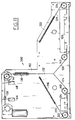
- an autoloader 10 made in accordance with the present invention positioned directly in front of an X-ray reader 12.
- the autoloader has a body 14 with a base 16 at the bottom and a monitor station 18 on top.
- the body 14 can be made of sheet metal or the like reinforced as necessary to support loads imposed by the autoloader components and x-ray cassettes 20 or pallets containing cassettes.
- the cassette is of the type wherein the photosensitive material is removed through one of the sides of the cassette.
- the cassette comprises shell having upper and lower panels and three side caps joining the upper and lower panels, and a removable end cap.
- a photographic element, such as stimulable phosphor plate, is provided within the cassette and is secured to the removable end cap.
- the end cap includes a latching mechanism for releasing the end cap from the cassette.
- a latch bar having at least one hook is used to latch or unlatch the latching mechanism.
- Monitor station 18 may include some means for preventing inadvertent movement of the monitor, such as indentations.
- body 14 has an access opening 24, as best seen by reference to Figure 2, through which the forward end of a cassette is passed so that the forward end of the cassette 20 is placed within the adjacent x-ray reader 12.
- body 14 has a portal 26 which is generally rectangular in shape and provides access to the interior of body 14. Facing portal 26 is an operator station, which may be occupied by an operator.
- Door assembly 32 of body 14 is operable between a closed position, as shown in Figure 1A, in which the portal 26 is closed and an open position, as shown in Figure 1 in which the interior of body 14 is accessible through portal 26.
- the door assembly includes a pair of panels 33,35 slideably mounted to body 14 such that when in the closed position the portal 26 is closed.
- any door assembly desired may be utilized.
- Autoloader 10 includes a retractable table 34, which can be moved between an extended stacking position, as shown in Figure 1 and a storage retracted position, inside body 14. In the storage retracted position the retractable table 34 is disposed totally within the body 14 so that the door assembly 32 can be closed as shown in Figure 1A.
- Table 34 can be used to hold x-ray cassettes 20 and/or pallets 22 containing cassettes during loading and unloading. Alternatively, x-ray cassette 20 can be loaded or unloaded from a cart not shown. Controls are provided to permit the operator to either open the door assembly 32 and have the table 34 extended automatically, or to open only the door 32 without extending of the retractable table.
- the autoloader is provided with a microprocessor which is appropriately linked up to various switches, motors and controls to operate the door assembly and retractable table and various other functions of the device in a pre-set pattern.
- a microprocessor which is appropriately linked up to various switches, motors and controls to operate the door assembly and retractable table and various other functions of the device in a pre-set pattern.
- Such controls are well known and therefore will not be discussed further.
- the autoloader is provided with a first and second conveyor assemblies 36, 38, respectively.
- Each conveyor assembly 36, 38 is provided with an endless cog belt 40.
- Each cog belt 40 having a plurality of regular space shelves 42.
- the cog belts 40 are aligned and driven such that the shelves 42 provide a plurality of vertically arranged cassette sites 44 within body 14.
- a read site 46 In line with the center of access opening 24 there is provided a read site 46 so that the cassette when placed in such position can be advanced for reading into the adjacent x-ray reader 12.
- the cassette sites 44 above reading site 46 are loading sites wherein cassettes which have yet to be read are placed. In the particular embodiment illustrated these loading sites are identified by numerals, one through ten, place on side panels 45,47 as shown in Figure 2.
- the cassettes sites 44 below read site 46 are unloading sites and are preferably identified by different indicia from that of loading sites.
- the unloading sites are identified by letters and in particular, by the letters A-J.
- Cassettes 20 can be interchanged between loading sites easily since each cassette is supported by a pair of vertically aligned shelves 42 and cassettes 20 are spaced apart from each other by a distance sufficient to permit each individual cassette 20 to be gripped while positioned fully to the back of every cassette site 44. While only one read site is provided, any number of loading and unloading sites may be provided as desired. In the particular embodiment illustrated, there are provided ten loading sites and ten unloading sites. To prevent accidental placement or attempted removal of a cassette from read site 46, a cross bar 49 is secured to body 14 in front of read site 46.
- the cog belts 40 are driven in unison by a drive means provided.
- a mechanism used to drive cog belts 40 is more fully described in copending application U.S. Serial No. 902,214.
- Such mechanism is used to in seriatim place cassettes at the read site for removal of the photosensitive material and delivery to the reader and to unloading sites after the photosensitive material has been returned to the cassette.
- the mechanism 50 also serves to return the cassette back to its respective cassette position when the reader has completed its reading operation and returned the photosensitive element back within the respective cassette.
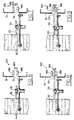
- the mechanism 50 includes a first pinch roller assembly 52 pivotally mounted to the frame 51 see Figure 2, as best seen by reference to Figure 2, of the conveyor assembly 36 and a second pinch roller assembly 54 which is also pivotally mounted to the frame of the conveyor assembly 38. While the first and second pinch roller assemblies 52,54 in the particular embodiment illustrated are shown mounted to the frame 51 of its respective conveyor assembly, the pinch roller assemblies 52,54 may be mounted directly to the frame 53 of the autoloader 10. The first and second pinch roller assemblies 52,54 are mounted in the same horizontal plane such that a cassette 20 positioned at the read site 46 may be firmly engaged therebetween.
- the first and second pinch roller assemblies are substantially identical, like numerals indicating like parts.
- the first and second pinch roller assemblies 52,54 each include a support arm 56 having a rear end 58 which is pivotally mounted to frame 51.
- the pinch roller assemblies 52,54 further include a support frame 60 located at the forward end 62 of the support arm 56.
- a motor 64 is secured to frame 60 and has a shaft 66 which extends through an opening, not shown, in frame 60.
- a pinch roller 70 designed to clampingly engage a cassette 20 located in the read site 46.
- pinch roller 70 is secured to shaft 66 by a Trantorque bushing 72 made by Fenner Manheim.
- Trantorque bushing 72 made by Fenner Manheim.
- pinch roller 70 may be secured to shaft 66 by any other means desired.
- the pinch roller 70 has an upper section 74 and a lower section 76.
- the upper section 74 has a substantially cylindrical drive surface 78.
- Drive surface 78 is preferably made of a material which is designed to grippingly engage the side of the adjacent cassette 20.
- the drive surface 78 comprises an outer layer 79 of an elastomeric material, and more particular, layer 79 is made of polyurethane. This assists in gripping the sides of the cassettes.
- the lower section 76 has a generally tapered support drive surface 80 which extends radially outward from the lower end of upper drive surface 78.
- the tapered support drive surface 80 is made of a hard durable material that can withstand the repeated riding of cassettes along the surface. In the particular embodiment illustrated the drive surface 80 is made of stainless steel.
- the drive surface 80 forms an angle a with respect to a plane perpendicular to upper drive surface 78.
- the angle ⁇ may have a wide range of values as desired, for example from 5° to 40°, preferably from 10° to 25°. In the particular embodiment illustrated a is 15 degrees.
- FIG. 10 there is illustrated the pivotal mounting of arm 56 and how it is mounted to frame 51.
- a block 82 having a cylindrical hole 84 which extends through the block 82 and is oriented such that the axis of the cylindrical hole 84 is substantially parallel to the axis of the shaft 66 of motor 64.
- a cylindrical mounting pin 86 extends through hole 84 and has a lower end 88 and an upper end 90. The pin 86 is secured to block 82 by set screw 91.
- the cylindrical mounting pin 86 is mounted between an upper mounting block 92 and lower mounting block 94 which are secured to frame 51 of the respective conveyor assembly.
- the upper mounting block 92 is provided with an elongated slot 96 which allows the pin 86 to move in a single direction substantially parallel to the direction of movement of the cassette 20 into reader 12.
- the lower end 88 has a ball mount 98 designed to be received within a generally spherical opening/socket provided in lower mounting block 94, thus providing a typical ball and socket joint.
- the ball mount 98 allows the pin to rotate in any direction.
- the elongated slot 96 in upper block 92 restricts movement of the pin such that the pin 86 can rotate only two axes, that is, rotation about the shaft axis as indicated by arrow 99 and about an axis perpendicular to the slot 96 and passing through the center of ball 98 as indicated by arrow 101. This motion allows the rollers 70 to follow the movement of the cassette 20 as it is fed into the reader 12 by allowing the arm 56 to tip up when the cassette moves up when clamped.
- the mechanism 50 for advancing and removing the cassette 20 from the reader further includes means for biasing the pinch rollers 70 at spaced rest position, moving the pinch rollers toward each other so that they engage the cassette therebetween, driving the cassette in a predetermined direction, and for releasing engagement therewith.
- a biasing mechanism 100 mounted to the back plate 102 of the autoloader 10.
- the biasing mechanism 100 includes a first slide bar 104 that is slideably mounted to back plate 102 and a second slide bar 106 which is also slideably mounted to back plate 102.
- the slide bar 104 has a capture recess 108 designed to receive a projection 110 secured to the forward end 62 of support frame of the first pinch roller assembly 52.
- the position of projection 110 in slide bar 104 is illustrated by a dotted line in Figure 3A.
- the second slide bar 106 is provided with a pair of capture recesses 112,113 for receiving a projection 114 formed at the forward end 62 of frame 60 of the second pinch roller assembly 54.
- the slots 108,112,113 have a generally U-shaped configuration with the open end facing upward. The sides of the slots have a height such that the projections placed therein can slide in a vertical direction to accommodate vertical movement of the pinch roller assemblies while still maintaining side contact for horizontal movement of the slide bar.
- the first capture recess 112 is designed to receive projection 114 when the cog belts 40 are positioned at a first predetermined distance apart and the second capture recess 113 is designed to receive the projection 114 when the cog belts 40 are placed in a second spaced position for receiving a cassette of a smaller size.
- the cog belts 40 are spaced apart such that the projection 114 is received in capture recess 112.
- a first torsion spring 116 is provided for normally biasing slide bar 104 such that the first pinch roller assembly 52 is positioned away from cassette 20.
- a second torsion spring 120 is provided for biasing the second slide bar 106 for maintaining the second pinch roller assembly in a position away from the other side of the cassette 20.
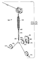
- a split cable 122 is provided having legs 124,126,128.
- Leg 124 is secured to slide bar 104
- second leg 126 is secured to the inner end of slide bar 106
- third leg 128 is secured to the lower end 129 of a spring 130.
- the upper end 131 of the spring 130 is connected to one end of drive cable 132, while the other end of the drive cable 132 is mounted to a take up reel 134 secured to a worm gear reduction assembly 138 which is secured to the autoloader in any conventional manner.
- FIG. 3B there is illustrated an enlarged view of the worm gear reduction assembly 138 which includes a motor 136, a worm 137 secured to the shaft of motor 136, a worm gear 139 which is operatively connected to take up reel 134 for winding of the cable 132 thereon.
- the motor 136 When the motor 136 is activated it will cause the take up reel 134 to provide a pulling force on drive cable 132.
- Idler pulleys 140,142 and 144 are provided so as to direct the motion of split cable 122 and drive cable 132 as it winds the drive cable 132 onto reel 134.
- idler pulley 140 is placed adjacent slide bar 104 such that a pulling force on leg 124 will cause the slide bar 104 to travel in a substantially horizontal direction toward the other slide bar.
- idler pulley 142 is mounted such that the pulling force applied to leg 126 of split cable 122 will cause the slide bar 106 to move in a substantially horizontal direction toward slide bar 104.
- Pulley 142 is positioned such that a pulling force is applied at a substantially vertical direction to the upper end of spring and thereby apply substantially equal force to both legs 124,126.
- spring 116 is slightly weaker then spring 120 so that arm stop 153 provided on frame 60 will determine the location of the left side of the cassette by locating against a mating surface stop on the autoloader or reader.
- spring 116 is designed to provide a force of 6 lbs and spring 120 is designed to provide force of 8 lbs of force, thus providing a 2 lbs force differential.
- spring 116 is designed to provide a force of 6 lbs and spring 120 is designed to provide force of 8 lbs of force, thus providing a 2 lbs force differential.
- the arm stop 153 provided on pinch roller assembly 52 to establish a reference point for locating one side of the cassette.
- the present invention is not so limited. If desired, the arm stop may be omitted and the strength of springs 116,120 may be made substantially equal. In this situation, the cassette when clamped by the pinch roller assemblies 52,54, as illustrated by Figure 5, would be able to freely move in the horizontal direction. This would allow the use of other means for aligning the cassette with the mechanism for extracting the photosensitive plate from the cassette.
- a pair of switches 146,148 are provided along the path of drive cable 132 which are electrically connected to microprocessor of the autoloader for controlling the operation of motor 136 as will be described later herein.
- An actuation member 150 is secured to the drive cable in between switches 146 and 148 and has a configuration such that it will engage either of the switches 146,148 as the cable is moved in that direction.
- switches 155 are place adjacent each of the arms 56 of pinch roller assemblies 52,54.
- the switches are appropriately electrically connected to the autoloader as is well known to those skilled in the art and are also connected to the microprocessor controlling the autoloader for monitoring the status of the pinch roller assemblies.
- the switches 155 are positioned such that when the arms 56 are in non engaged position with respect to the cassette 20 as illustrated in Figure 4 the switches 155 are engaged and when the pinch roller assemblies are in the engaged position with respect to the cassette 20 the switches are not engaged as illustrated in Figure 5.
- Means are also provided for monitoring the position of the cassette at the read site 46 and for controlling the operation of motors 64 so that the cassette can be properly positioned back on the shelves at the read site 46.
- a light sensor assembly 154 is provided adjacent the cassette 20 at opening 24.
- the light sensor assembly 154 includes a light source 158 and a sensor 160 which are positioned such assembly 154 will sense when a cassette 20 is passing through opening 24 and when the leading or trailing edge as viewed from the direction of travel of the cassette of the cassette 20 passes that point.
- the cog belts 40 can be prevented from operating if a cassette is present in this area.
- the light sensor assembly 154 can be used to monitor the trailing edge of the cassette 20 and turn power off to motors 64 so that the cassette 20 can be properly placed back on the shelf at the read site.
- a cable assembly 159 includes a block 162 having an generally circular opening 164 for receiving a circular pulley 166 designed to fit with opening 164.
- Pulley 166 has an annular groove 168 about its periphery.
- the block 162 also includes a slot 170 which extents from the bottom of the block 162 up to about to the top of the opening 164 and is sized so that cable 172 can pass through slot 170 and engage pulley 166 within groove 168 in pulley 166.
- the cable 172 has a first end 174 secured to slide bar 104 and a second end 176 secured to slide bar 106.
- a connecting rod 178 is provided having a threaded lower end 180 designed to engage a threaded opening 181 provided on the top of block 162 and an upper end having an opening 182 designed to engage the lower end of spring 130.
- FIG. 11 there is illustrated of a modified biasing means 200 which is similar to biasing mechanism 100, like numerals indicating like parts. The only difference being the manner in which the slide bars 104,106 are biased.
- coil springs 216,220 are used in conjunction with a pair of idler pulleys 222,224 and connecting cables 223,225.
- Cable 223 having one end connected to one end of spring 216 and the other end of cable 223 being connected to slide bar 104 opposite leg 124 of cable 122.
- Cable 225 having one end connected to one end of spring 220 and the other end of cable 225 being connected to slide bar 106 opposite leg 126 of cable 122.
- the second end of springs 216,220 being anchored to the back plate of the autoloader 10.
- the springs 216,220 apply a biasing force so as to maintain the slide bars and associated pinch roller assemblies away from each other, as illustrated in Figure 4.
- the operator opens the door assembly to the autoloader 10 and places cassettes 20 to be read in the loading sites 44.
- the cassettes 20 may be placed directly on the shelves or on pallets designed to receive the cassettes which are in turn designed for placement on the shelves. Any cassettes that have been read and are present in the unloading sites 44 may also be removed by the operator.
- the operator will close the door assembly 32 and allow the autoloader to operate in its designed operational mode. Accordingly, the autoloader 10 then operates the endless cog belts 40 so as to locate the appropriate cassette at the read site 46.
- the cassette 20 will be in the position as illustrated in Figures 4 and 6. Thereafter the biasing mechanism 100 is activated by turning on motor 136 winding drive cable 132 on to take up reel 134 which causes a pulling force to be applied to spring 130. The pulling force is transmitted through spring 130 to the third leg 128. The force is then transmitted to first and second legs 124 and 126 which, in turn, causes the force to be applied to slide bars 104,106 resulting in the slide bars 104,106 being moved toward each other. Since projection 110 of support frames are secured to the frame of each of the roller assemblies 52,54 the pinch roller assemblies 52,54 will be caused to be moved toward each other and clampingly engage the cassette 20 placed therebetween.
- FIG. 15-17 there is illustrated an optional sensor means for determining if a cassette is properly positioned at the retaining site directly above the read site 46.
- FIG 15 there is illustrated a perspective view of a portion of the mechanism 50 illustrated in Figure 1-14, like numerals indicating like parts.
- Sensor assembly 160 is disposed atop support frame 60 and includes a switch 171 having a activation member 173 designed to engage the sides of a cassette placed in the retaining site directly above the read site 46. When no cassette is present in the cassette retaining site directly above the reading site 46, the activation members 173 will be fully extended.
- the activation members 173 will be depressed so as to provide an appropriate signal to the microprocessor control unit.
- FIG 16 there is illustrated a cassette which has one side placed in the cassette retaining site directly above the read site 46 and the other side placed in the next above cassette retaining site. As can be seen, the cassette is not properly placed in a single cassette retaining site and can not be properly fed to the adjacent reader. In this situation only one of the activation members will be depressed, therefore, only one of the switches 171 will send a signal to the microprocessor.
- the microprocessor can be properly programmed to note that only one of the switches 171 has been activated and this can stop the autoloader from any further action that can cause damage and provide an appropriate error message to the operator. While in the particular embodiment illustrated sensor assembly is a mechanical sensor, it is to be understood that any desired sensor may be utilized to determine if the side of the cassette is in the adjacent retaining site.
- FIG. 6-9 there is illustrated in sequence the movement of a cassette 20 being fed into the reader 12.
- an opening 24 through which the cassette 20 is fed from the autoloader 10 into the adjacent reader 12.
- a clamping mechanism 152 for clamping of a cassette 20 after it has been fed into the reader 12.
- the clamping mechanism comprises a backstop 184 and upper clamp jaw 186 and lower clamp jaw 188.
- the forward end of the cassette will be lifted from the shelves such that only the trailing edge of the cassette will be dragged along the shelf.
- the cassette is moved into the reader until it hits backstop 184 as illustrated in Figure 8.
- the motors 64 are left on until the cassette has been completely clamped as illustrated in Figure 9. This lifts the cassette 20 off the cog belts 40. At this time the motors 64 are turned off and the pinch roller assemblies 52,54 are returned to the disengaged position by springs 116,120 as illustrated in Figure 4. Thereafter the photographic element to be read is removed from the cassette 20 in any desired manner. In one particular embodiment, this is done through a mechanism as set forth a patent application filed concurrently herewith entitled "Reader Having Cassette Locating and Unlatching Mechanism" of Roger Brahm and James Lattimore.
- the cassette in the clamped position is substantially free of any contact with the autoloader. Thus, in this position no substantial vibration will be transferred from the autoloader to the reader.
- the autoloader activates the endless cog belts 40 such that the cassette at the next higher cassette site 44 is moved to the reading site 46 wherein the entire process is repeated.
- the cassette that has been read is lowered to one of the unload positions identified by letters A-J as illustrated in Figure 2.
- the present invention provides a mechanism for transferring of cassettes from the autoloader to an adjacent reader and back to the autoloader in a reliable manner while also precisely positioning of the cassette within the reader to allow proper clamping of the cassette and permit removal of the storage phosphorous film therein.
- the mechanism is also designed to minimize transfer of vibration to the reader which can adversely affect the reading of the photographic element.
Landscapes
- Engineering & Computer Science (AREA)
- Multimedia (AREA)
- Signal Processing (AREA)
- Radiography Using Non-Light Waves (AREA)
- Sheets, Magazines, And Separation Thereof (AREA)
Applications Claiming Priority (2)
| Application Number | Priority Date | Filing Date | Title |
|---|---|---|---|
| US07/981,719 US5328019A (en) | 1992-11-25 | 1992-11-25 | Autoloader for cassettes and/or pallet |
| US981719 | 1992-11-25 |
Publications (2)
| Publication Number | Publication Date |
|---|---|
| EP0599086A1 true EP0599086A1 (de) | 1994-06-01 |
| EP0599086B1 EP0599086B1 (de) | 1998-07-08 |
Family
ID=25528602
Family Applications (1)
| Application Number | Title | Priority Date | Filing Date |
|---|---|---|---|
| EP93117633A Expired - Lifetime EP0599086B1 (de) | 1992-11-25 | 1993-10-30 | Automatische Ladevorrichtung für Kassetten und/oder Palette |
Country Status (4)
| Country | Link |
|---|---|
| US (1) | US5328019A (de) |
| EP (1) | EP0599086B1 (de) |
| JP (1) | JPH0777751A (de) |
| DE (1) | DE69319547T2 (de) |
Cited By (1)
| Publication number | Priority date | Publication date | Assignee | Title |
|---|---|---|---|---|
| EP0601355B1 (de) * | 1992-11-25 | 1997-09-10 | Eastman Kodak Company | Lesegerät mit einem Kassettenauffinde- und Entriegelungsmechanismus |
Families Citing this family (8)
| Publication number | Priority date | Publication date | Assignee | Title |
|---|---|---|---|---|
| US5277322A (en) * | 1992-11-25 | 1994-01-11 | Eastman Kodak Company | Pallet for holding a cassette |
| US5315632A (en) * | 1992-11-25 | 1994-05-24 | Eastman Kodak Company | Cassette clamping mechanism |
| US5493128A (en) | 1994-08-25 | 1996-02-20 | Eastman Kodak Company | Method and apparatus for indexing cassettes |
| DE19745011A1 (de) * | 1997-10-11 | 1999-04-15 | Eastman Kodak Co | Vorrichtung zur vereinfachten vertikalen Einführung einer Röntgenkassette in eine Transportaufnahme eines Bearbeitungsgeräts für Röntgenkassetten |
| ATE334398T1 (de) * | 2000-09-05 | 2006-08-15 | Tecan Trading Ag | Träger für eine mikrotiterplatte |
| US7368747B2 (en) * | 2004-12-17 | 2008-05-06 | Carestream Health, Inc. | Short U-flow multicassette autoloader for a storage phosphor reader |
| US7777192B2 (en) * | 2007-09-05 | 2010-08-17 | Fujifilm Corporation | Cassette system |
| AU2013364077C1 (en) | 2012-12-21 | 2018-03-22 | Alcon Inc. | Cassette clamp mechanism |
Citations (8)
| Publication number | Priority date | Publication date | Assignee | Title |
|---|---|---|---|---|
| US4317138A (en) * | 1980-02-11 | 1982-02-23 | Exxon Research & Engineering Co. | Method and apparatus for facsimile sheet handling |
| DE3309220A1 (de) * | 1983-03-15 | 1984-09-20 | Siemens AG, 1000 Berlin und 8000 München | Vorrichtung zum beladen von blattfilmmagazinen |
| DE3800249A1 (de) * | 1987-01-07 | 1988-07-21 | Fuji Photo Film Co Ltd | Automat fuer die entnahme von filmblaettern aus magazinen |
| EP0278238A1 (de) * | 1987-01-13 | 1988-08-17 | Fuji Photo Film Co., Ltd. | Strahlungsbildaufzeichnungs- und -wiedergabevorrichtung |
| US4786807A (en) * | 1986-03-17 | 1988-11-22 | Fuji Photo Film Co., Ltd. | Radiation image read-out apparatus |
| EP0422621A2 (de) * | 1989-10-11 | 1991-04-17 | Fuji Photo Film Co., Ltd. | Bildlesegerät |
| EP0452931A2 (de) * | 1990-04-20 | 1991-10-23 | Fuji Photo Film Co., Ltd. | Zuführgerät für Kopierkassetten |
| US5073829A (en) * | 1989-09-05 | 1991-12-17 | Konica Corporation | Cassette supply apparatus |
Family Cites Families (14)
| Publication number | Priority date | Publication date | Assignee | Title |
|---|---|---|---|---|
| SE337104B (de) * | 1970-03-10 | 1971-07-26 | Kockum Soederhamn Ab | |
| US3687260A (en) * | 1971-01-20 | 1972-08-29 | Potlatch Forests Inc | Edging picker |
| US3811586A (en) * | 1972-02-24 | 1974-05-21 | G Lavoie | Bag opening and emptying machine |
| US3858708A (en) * | 1972-10-27 | 1975-01-07 | Amf Inc | Method and apparatus for manipulating rod-like articles |
| US3902773A (en) * | 1973-03-09 | 1975-09-02 | Sperry Rand Corp | Article storage apparatus |
| US3844399A (en) * | 1973-03-09 | 1974-10-29 | Beloit Passavant Corp | Log conveying apparatus |
| US4479572A (en) * | 1981-11-10 | 1984-10-30 | Merz William J | Conveyor system |
| US4561819A (en) * | 1984-02-15 | 1985-12-31 | Ironica, Inc. | Flat article conveyor |
| JPS61273441A (ja) * | 1985-05-23 | 1986-12-03 | Canon Inc | ウエハ搬送装置 |
| US4789782A (en) * | 1986-08-15 | 1988-12-06 | Fuji Photo Film Co., Ltd. | Radiation image recording and reproducing system |
| US4892455A (en) * | 1987-05-21 | 1990-01-09 | Hine Derek L | Wafer alignment and transport mechanism |
| JPH01226626A (ja) * | 1988-03-08 | 1989-09-11 | Dainippon Printing Co Ltd | 印刷機排紙部の台車入替装置 |
| US4875670A (en) * | 1988-11-17 | 1989-10-24 | Ncr Corporation | Floating idler wheel arm assembly for a document transport |
| US5020579A (en) * | 1990-05-21 | 1991-06-04 | Strong Manufacturing | Automatic infeed control |
-
1992
- 1992-11-25 US US07/981,719 patent/US5328019A/en not_active Expired - Fee Related
-
1993
- 1993-10-30 DE DE69319547T patent/DE69319547T2/de not_active Expired - Fee Related
- 1993-10-30 EP EP93117633A patent/EP0599086B1/de not_active Expired - Lifetime
- 1993-11-25 JP JP5295099A patent/JPH0777751A/ja active Pending
Patent Citations (8)
| Publication number | Priority date | Publication date | Assignee | Title |
|---|---|---|---|---|
| US4317138A (en) * | 1980-02-11 | 1982-02-23 | Exxon Research & Engineering Co. | Method and apparatus for facsimile sheet handling |
| DE3309220A1 (de) * | 1983-03-15 | 1984-09-20 | Siemens AG, 1000 Berlin und 8000 München | Vorrichtung zum beladen von blattfilmmagazinen |
| US4786807A (en) * | 1986-03-17 | 1988-11-22 | Fuji Photo Film Co., Ltd. | Radiation image read-out apparatus |
| DE3800249A1 (de) * | 1987-01-07 | 1988-07-21 | Fuji Photo Film Co Ltd | Automat fuer die entnahme von filmblaettern aus magazinen |
| EP0278238A1 (de) * | 1987-01-13 | 1988-08-17 | Fuji Photo Film Co., Ltd. | Strahlungsbildaufzeichnungs- und -wiedergabevorrichtung |
| US5073829A (en) * | 1989-09-05 | 1991-12-17 | Konica Corporation | Cassette supply apparatus |
| EP0422621A2 (de) * | 1989-10-11 | 1991-04-17 | Fuji Photo Film Co., Ltd. | Bildlesegerät |
| EP0452931A2 (de) * | 1990-04-20 | 1991-10-23 | Fuji Photo Film Co., Ltd. | Zuführgerät für Kopierkassetten |
Cited By (1)
| Publication number | Priority date | Publication date | Assignee | Title |
|---|---|---|---|---|
| EP0601355B1 (de) * | 1992-11-25 | 1997-09-10 | Eastman Kodak Company | Lesegerät mit einem Kassettenauffinde- und Entriegelungsmechanismus |
Also Published As
| Publication number | Publication date |
|---|---|
| EP0599086B1 (de) | 1998-07-08 |
| DE69319547D1 (de) | 1998-08-13 |
| JPH0777751A (ja) | 1995-03-20 |
| DE69319547T2 (de) | 1999-02-11 |
| US5328019A (en) | 1994-07-12 |
Similar Documents
| Publication | Publication Date | Title |
|---|---|---|
| EP0157801B1 (de) | Zufuhr-, transport- und ausgabeeinrichtung für karten in einer automatischen prägevorrichtung | |
| EP0599086B1 (de) | Automatische Ladevorrichtung für Kassetten und/oder Palette | |
| EP0463786B1 (de) | Kassettenladevorrichtung zum Anpassen von Kassetten verschiedener Grösse in einem Bandkassettenaufzeichnungs- und/oder -wiedergabegerät | |
| EP0494229A1 (de) | Automatische ladevorrichtung für magnetbandkassetten. | |
| EP0452931B1 (de) | Zuführgerät für Kopierkassetten | |
| US3790162A (en) | Picking and transporting apparatus and method | |
| CN117985583B (zh) | 一种基于仓储用的布卷搬运吊具 | |
| US5553839A (en) | System for handling curved form media and cassette therefor | |
| US5558320A (en) | Lifting shoe for media handling and related cassette media holder | |
| US5319217A (en) | Door assembly for cassette autoloader | |
| US4930147A (en) | Cassette film transport | |
| US5174560A (en) | Sheet supply apparatus | |
| US5605429A (en) | Door safety system for storage phosphor cassette autoloader | |
| US5104215A (en) | Microfilm cartridge storage and retrieval system | |
| JP4015777B2 (ja) | 容器の誤挿入防止構造および容器処理装置 | |
| EP0747753B1 (de) | Abtastgerät für PSL Radiographie mit Kassettenstapler | |
| CN1080894C (zh) | 胶片卷取装置 | |
| JPH0543066A (ja) | 給紙装置 | |
| EP1533805A2 (de) | Robotiksystem für Datenspeichervorrichtung | |
| EP0607521B1 (de) | Automatische kassettenladenvorrichtung | |
| JP2584886B2 (ja) | シート材取出装置 | |
| JPH0248838Y2 (de) | ||
| US5911415A (en) | Collecting cassette for use with a media sheet handling system | |
| JPH0244283Y2 (de) | ||
| JPH0551837U (ja) | 原稿カセット供給装置におけるカセットガイド機構 |
Legal Events
| Date | Code | Title | Description |
|---|---|---|---|
| PUAI | Public reference made under article 153(3) epc to a published international application that has entered the european phase |
Free format text: ORIGINAL CODE: 0009012 |
|
| AK | Designated contracting states |
Kind code of ref document: A1 Designated state(s): DE FR GB IT |
|
| 17P | Request for examination filed |
Effective date: 19941115 |
|
| 17Q | First examination report despatched |
Effective date: 19961202 |
|
| GRAG | Despatch of communication of intention to grant |
Free format text: ORIGINAL CODE: EPIDOS AGRA |
|
| GRAG | Despatch of communication of intention to grant |
Free format text: ORIGINAL CODE: EPIDOS AGRA |
|
| GRAG | Despatch of communication of intention to grant |
Free format text: ORIGINAL CODE: EPIDOS AGRA |
|
| GRAH | Despatch of communication of intention to grant a patent |
Free format text: ORIGINAL CODE: EPIDOS IGRA |
|
| GRAH | Despatch of communication of intention to grant a patent |
Free format text: ORIGINAL CODE: EPIDOS IGRA |
|
| GRAA | (expected) grant |
Free format text: ORIGINAL CODE: 0009210 |
|
| ITF | It: translation for a ep patent filed | ||
| AK | Designated contracting states |
Kind code of ref document: B1 Designated state(s): DE FR GB IT |
|
| REF | Corresponds to: |
Ref document number: 69319547 Country of ref document: DE Date of ref document: 19980813 |
|
| ET | Fr: translation filed | ||
| PLBE | No opposition filed within time limit |
Free format text: ORIGINAL CODE: 0009261 |
|
| STAA | Information on the status of an ep patent application or granted ep patent |
Free format text: STATUS: NO OPPOSITION FILED WITHIN TIME LIMIT |
|
| 26N | No opposition filed | ||
| PGFP | Annual fee paid to national office [announced via postgrant information from national office to epo] |
Ref country code: GB Payment date: 20010914 Year of fee payment: 9 |
|
| PGFP | Annual fee paid to national office [announced via postgrant information from national office to epo] |
Ref country code: FR Payment date: 20011005 Year of fee payment: 9 |
|
| PGFP | Annual fee paid to national office [announced via postgrant information from national office to epo] |
Ref country code: DE Payment date: 20011030 Year of fee payment: 9 |
|
| REG | Reference to a national code |
Ref country code: GB Ref legal event code: IF02 |
|
| PG25 | Lapsed in a contracting state [announced via postgrant information from national office to epo] |
Ref country code: GB Free format text: LAPSE BECAUSE OF NON-PAYMENT OF DUE FEES Effective date: 20021030 |
|
| PG25 | Lapsed in a contracting state [announced via postgrant information from national office to epo] |
Ref country code: DE Free format text: LAPSE BECAUSE OF NON-PAYMENT OF DUE FEES Effective date: 20030501 |
|
| GBPC | Gb: european patent ceased through non-payment of renewal fee | ||
| PG25 | Lapsed in a contracting state [announced via postgrant information from national office to epo] |
Ref country code: FR Free format text: LAPSE BECAUSE OF NON-PAYMENT OF DUE FEES Effective date: 20030630 |
|
| REG | Reference to a national code |
Ref country code: FR Ref legal event code: ST |
|
| PG25 | Lapsed in a contracting state [announced via postgrant information from national office to epo] |
Ref country code: IT Free format text: LAPSE BECAUSE OF NON-PAYMENT OF DUE FEES;WARNING: LAPSES OF ITALIAN PATENTS WITH EFFECTIVE DATE BEFORE 2007 MAY HAVE OCCURRED AT ANY TIME BEFORE 2007. THE CORRECT EFFECTIVE DATE MAY BE DIFFERENT FROM THE ONE RECORDED. Effective date: 20051030 |