EP0607521B1 - Automatische kassettenladenvorrichtung - Google Patents
Automatische kassettenladenvorrichtung Download PDFInfo
- Publication number
- EP0607521B1 EP0607521B1 EP93118485A EP93118485A EP0607521B1 EP 0607521 B1 EP0607521 B1 EP 0607521B1 EP 93118485 A EP93118485 A EP 93118485A EP 93118485 A EP93118485 A EP 93118485A EP 0607521 B1 EP0607521 B1 EP 0607521B1
- Authority
- EP
- European Patent Office
- Prior art keywords
- cassette
- cassettes
- sites
- reader
- autoloader
- Prior art date
- Legal status (The legal status is an assumption and is not a legal conclusion. Google has not performed a legal analysis and makes no representation as to the accuracy of the status listed.)
- Expired - Lifetime
Links
Images


Classifications
-
- G—PHYSICS
- G03—PHOTOGRAPHY; CINEMATOGRAPHY; ANALOGOUS TECHNIQUES USING WAVES OTHER THAN OPTICAL WAVES; ELECTROGRAPHY; HOLOGRAPHY
- G03B—APPARATUS OR ARRANGEMENTS FOR TAKING PHOTOGRAPHS OR FOR PROJECTING OR VIEWING THEM; APPARATUS OR ARRANGEMENTS EMPLOYING ANALOGOUS TECHNIQUES USING WAVES OTHER THAN OPTICAL WAVES; ACCESSORIES THEREFOR
- G03B42/00—Obtaining records using waves other than optical waves; Visualisation of such records by using optical means
- G03B42/02—Obtaining records using waves other than optical waves; Visualisation of such records by using optical means using X-rays
- G03B42/04—Holders for X-ray films
- G03B42/045—Holders for X-ray films apparatus for loading or unloading the holders
Definitions
- the present invention pertains to an autoloader for feeding cassettes and/or pallets containing cassettes to and receiving them from a computed radiographic reader.
- Storage phosphorous film is read by photoelectrically detecting an image formed by scanning with stimulating radiation.
- An example of such a scanner/reader is disclosed in US-A-4,789,782.
- Such a cassette is disclosed in EP-A-0 544 138.
- a hook extractor can be used with the x-ray cassette to remove the photographic element for scanning in the x-ray reader. It is desirable to provide an apparatus to automate the presentation of such x-ray cassettes or similar cassettes to such an extractor so that a number of x-ray cassettes could be processed in succession without attention from an operator.
- Such an apparatus be able to accurately position x-ray cassettes and/or pallets containing cassettes sequentially to simplify removal and reinsertion of the photographic elements and that the presentation apparatus be separate from the x-ray reader to permit interchange of units and reduce repair time.
- An example of a suitable device for presenting cassettes is disclosed in EP-B1-0 544 326.
- a positioner/autoloader for use with a plurality of x-ray cassettes and/or pallets containing cassettes which comprise first and second cog belts spaced apart so as to provide a plurality of cassette retaining sites one of which defines a cassette read site for presenting of the cassette to the reader.
- the belts are driven such that the cassettes are each individually positioned at the read site for removal of the photosensitive film therein for reading by the reader after which it is returned to the cassette.
- the positioner allows a plurality of individual cassettes to be placed thereon for automatic supplying to the reader thus freeing the operator to accomplish other duties. It is important that the mechanism be designed to operate in such a manner so as to minimize any transfer of vibrations from the autoloader to the reader which can adversely affect the reader reading the information stored on the photo stimulable phosphorous film.
- the autoloader will be loaded or unloaded during scanning of the photostimulable phosphorous film in the adjacent reader.
- the cassettes are manually loaded and unloaded from the cassette loading and unloading sites.
- the operator will be loading or unloading a plurality of cassettes. During this procedure the operator must align the sides of the cassettes with axially spaced shelves. Thus, there is the possibility that the cassette will be banged against the sides of the autoloader adjacent the portal which could cause objectionable vibrations to be transmitted to the reader. Since the shelves forming the cassette retaining sites are spaced apart, the operator must rely on his or her ability to visually align the sides of the cassette with the appropriate opposed aligned shelves. If the cassette is not properly inserted into the cassette site, the cassette could be placed at an angle between non aligned shelves which would result in the autoloader stopping when the autoloader senses the misalignment.
- a copy cassette supplying apparatus includes a cassette holder having a vertical array of steps for holding copy cassettes thereon.
- This cassette holder includes a plurality of guide rollers disposed between the steps for guiding copy cassettes when the cassettes are moved onto and off the steps so that a misalignment can be prevented.
- there exists a problem in the prior art in providing an apparatus having means for minimizing transfer of vibrations to the reader which can adversely affect the reading of the photographic element and means for assisting the operator to quickly and easily load cassettes between properly aligned shelves of the cassette retaining sites.
- a cassette autoloader is provided as defined in claim 1.
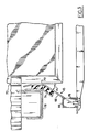
- the autoloader 10 is illustrated in accordance with the present invention positioned directly in front of an X-ray reader 12.
- the autoloader 10 has a body 14 with a base 16 at the bottom and a monitor station 18 on top.
- the body 14 can be made of sheet metal or the like reinforced as necessary to support loads imposed by the autoloader components and x-ray cassettes 20 or pallets containing cassettes.
- the cassette 20 is of the type wherein the photosensitive material is removed through one of the sides of the cassette such as that described in EP-A2-0 544 138, previously referred to herein.
- the cassette comprises a shell having upper and lower panels and three side caps joining the upper and lower panels, and an removable end cap.
- a photographic element such as a stimulable phosphor plate, is provided within the cassette and is secured to the removable end cap.
- the end cap includes a latching mechanism for releasing the end cap from the cassette.
- a latch bar having at least one hook is used to latch or unlatch the latching mechanism.
- other cassette construction may be used as appropriate, such as that disclosed in US-A-5,065,866 and US-A-5,090,567.
- a further example of a suitable pallet for use in the autoloader 10 is described in copending application US-A-5,277,322 entitled "Pallet for Holding a Cassette" of John Boutet, James F. Owen, Wayne Arseneault, Jeff Yaskow, and T. Dale Baker.
- Monitor station 18 may include some means for preventing inadvertent movement of the monitor 23, such as indentations.
- body 14 has an access opening 24, as best seen by reference to Figure 1A, through which the forward end of a cassette is passed so that the forward end of the cassette 20 is placed within the adjacent x-ray reader 12.
- portal 26 is generally rectangular in shape and provides access to the interior of body 14. Facing portal 26 is an operator station, which may be occupied by an operator.
- Door assembly 32 of body 14 is operable between a closed position, in which the portal 26 is closed and an open position, as shown in Figure 2 in which the interior of body 14 is accessible through portal 26.
- door assembly 32 The operation and function of door assembly 32 is set forth in greater detail in copending application US-A-5,319,217 entitled "Door Assembly For Cassette Autoloader” filed concurrently herewith of Wayne Arseneault, John C. Boutet, Darryl D. DeWolff, James Lattimore, Gary Shope, T. Dale Baker, and Jeffrey J. Yaskow.
- the door assembly includes a pair of panels 33, 35 slideably mounted to body 14 such that when in the closed position the portal 26 is closed.
- any door assembly desired may utilized.
- Autoloader 10 includes a retractable table 34, which can be moved between an extended stacking position, as shown in Figure 1, and a storage retracted position inside body 14. In the storage retracted position the retractable table 34 is disposed totally within the body 14 so that the door assembly 32 can be closed as shown in Figure 1.
- Table 34 can be used to hold x-ray cassettes 20 and/or pallets 22 containing cassettes during loading and unloading. The details of the construction and operation of the retractable table 34 is described in greater detail in copending application flied concurrently with the present invention (US Serial No. 981,630) of John C. Boutet, Darryl D. DeWolff, James Lattimore, James J. Sheridan and Jeffrey J.
- x-ray cassette 20 can be loaded or unloaded from a cart (not shown).
- Controls are provided to permit the operator to either open the door assembly 32 and have the table 34 extended automatically or to open only the door 32 without extending of the retractable table 34.
- a wide variety of means may be employed for controlling operation of the autoloader which are well known in the prior art.
- the autoloader is provided with a microprocessor which is appropriately linked up to various switches, motors and controls to operate the door assembly and retractable table and various other functions of the device in a pre-set pattern. Such controls are well known and therefore will not be discussed further.
- the autoloader is provided with a first and second conveyor assemblies 36, 38, respectively.
- Each conveyor assembly 36, 38 is provided with an endless cog belt 40.
- Each cog belt 40 having a plurality of regularly spaced shelves 42.
- the cog belts 40 are aligned and driven such that the shelves 42 provide a plurality of vertically arranged cassette retaining sites 44 within body 14.
- a read site 46 In line with the center of access opening 24 there is provided a read site 46 whereby the cassette when placed in such position can be advanced for reading into the adjacent x-ray reader 12.
- the cassette retaining sites 44 above reading site 46 are loading sites wherein cassettes which have yet to be read are placed.
- Cassette retaining sites 44 below read site 46 are unloading sites from which scanned and erased cassettes can be removed.
- cassette loading and unloading sites may be provided as desired. In the particular embodiment illustrated, there are provided ten loading sites and ten unloading sites.
- a guide bar 49 is secured to body 14 in front of read site 46. Cassettes 20 can be interchanged between loading sites easily since each cassette is supported by a pair of vertically aligned shelves 42, and shelves 42 are spaced apart from each other by a distance sufficient to permit each individual cassette 20 to be gripped while positioned fully to the back of every cassette retaining site 44.
- the cog belts 40 are driven in unison by a drive means provided.
- a drive means provided.
- An example of a mechanism used to drive cog belts 40 is more fully described in EP-C-0 544 326 previously referred to herein. Such mechanism is used to in seriatim place cassettes at the read site for removal of the photosensitive material and delivery to the reader and to unloading sites after the photosensitive material has been returned to the cassette.
- the side panels 45, 47 adjacent portal 26 are provided with identifying indicia.
- the loading sites are identified by numerals, one through ten, placed on side panels 45, 47 and the cassette unloading sites 44 below read site 46 are preferably identified by different indicia from that of loading sites.
- the unloading sites are identified by letters and in particular, by the letters A-J.
- the indicia on the sides panels 45, 47 is such that common indicia on opposed side panels 45, 47 indicate a particular cassette site.
- the panels 45, 47 serve to assist in guiding the cassettes into the cassette retaining sites.
- the panels 45, 47 each comprise guide section 68 and a rear mounting section 70.
- the rear mounting section 70 is substantially parallel to the side 72 of the adjacent cog belt which forms one side of the cassette retaining site as is best seen in Figure 3. While only one of the guide panels, panel 45, is shown in Figure 3, it is to be understood that the other guide panel, panel 47, is similarly constructed.
- the guide section 68 extends from the rear mounting section 70 at an angle ⁇ with respect to a plane which is parallel to the direction of insertion of the cassette into the autoloader. The angle ⁇ may have a wide range of angles.
- angle ⁇ ranges from 10 degrees to 60 degrees, preferably from 20 to 45 degrees. In the particular embodiment illustrated angle ⁇ is 33 degrees.
- the guide panels are subject to repeated hitting during insertion of the cassettes into the cassette retaining sites which can produce shock vibrations which can affect the adjacent reader.
- the guide panels 45, 47 are vibration isolated by mounting to the autoloader 10.
- the panels 45, 47 are each mounted to the autoloader by elastomeric mounts 74 located along the length of the panels.
- the elastomeric mounts are made of a material which does not transmit vibration readily therethrough.
- mounts 74 are made of a urethane foam material which absorbs shocks.
- mounts 74 were made of Isoloss LS 1525TM Urethane purchased from EAR Inc.
- the mounts 74 are secured to central guide section 68 and the frame 78 of the adjacent conveyor assembly.
- the mounts 74 may be secured to frame 78 and guide panel 45 in any desired manner.
- an adhesive is applied between the surface of the mount 74 and adjacent frame and panel.
- the forward end of the guide section 68 at the read site is attached to a standoff 76 by means of a tab 80 formed in the panel 45.
- the front end of standoff 76 is secured to guide bar 49. Any shocks introduced to the guide bar 49 are absorbed by the mounts 74 associated with each panel 45, 47. Accordingly little or no vibrations will be transmitted to the reader.
- the guide bar 49 prevents cassettes from being inserted into or removed from the read site.
- the guide bar 49 is also designed to assist the operator in placing cassettes into the autoloader.
- the guide bar 49 is provided with a top edge 83, the guide being positioned on the panels so that the top edge 83 corresponds with the bottom of the loading site directly above the read site.
- the operator can rest the front portion of a cassette on the top edge 83 and then simply slide the cassette into the adjacent loading site identified by the numeral 1.
- the operator can use the filled loading site #1 to further assist in identifying the next loading site directly above.
- the guide bar 49 is provided with cut out sections 85 to assist the operator in placing or removing cassettes in the cassette sites above and below the read site.
- a guide strip 86 is placed on guide bar 49 in an asymmetric manner.
- guide strip 86 is disposed in the left half of the guide bar 49.
- Guide strip 86 is designed to align with a guide strip 87 placed on the back edge of cassette and/or pallet containing a cassette so that when the cassette (or pallet) is properly placed in the shelves, the guide strips 86, 87 will be vertically aligned.
- the guide strip placed on a pallet will align with the cassette it is designed to hold and thus also make loading of the cassette easier.
- guide strips are a strip of a color different from the guide bar and cassette. In the embodiment illustrated, guide strips 86, 87 are yellow.
- the present invention provides means in an autoloader for minimizing transfer of vibrations to a reader which can adversely affect the reading of the photographic element and means for assisting the operator to quickly and easily load cassettes between properly aligned shelves of the loading sites.
Landscapes
- Physics & Mathematics (AREA)
- General Physics & Mathematics (AREA)
- Radiography Using Non-Light Waves (AREA)
- Warehouses Or Storage Devices (AREA)
- Sheets, Magazines, And Separation Thereof (AREA)
- Apparatus For Radiation Diagnosis (AREA)
Claims (5)
- Gerät (10) zum Aufbewahren und automatischen Transportieren von Kassetten (20) und/oder mit Kassetten bestückten Paletten zu einem Lesegerät (12), mit Aufbewahrungs- und Fördermitteln, die einen Kassettenlesebereich (46) bilden, in dem die dort eingelegte Kassette zum Lesen in das Lesegerät transportierbar ist, mit einer Vielzahl von Kassettenhaltebereichen (44), mit Mitteln zum Bewegen der Aufbewahrungs- und Fördermittel derart, daß in den Kassettenhaltebereichen (44) befindliche Kassetten nacheinander durch den Lesebereich (46) förderbar sind, und mit einem die Aufbewahrungs- und Fördermittel umschließenden Gehäuse (14), das mit einer an die Kassettenhaltebereiche angrenzenden Öffnung (26) versehen ist, durch die Kassetten in die Aufbewahrungs- und Fördermittel einlegbar oder aus diesen entnehmbar sind, gekennzeichnet durch
Mittel, die die Übertragung von durch das Einlegen von Kassetten in die Kassettenhaltebereiche verursachten Stoßschwingungen auf das Gehäuse des Geräts und das angrenzende Lesegerät (12) auf ein Minimum reduzieren, wobei die Mittel zum Überführen der Kassetten in die Kassettenaufbewahrungsbereiche mit Führungselementen (45, 47) versehen sind, die jeweils mittels entlang den Führungselementen angeordneter, elastomerer Halterungen (74) am Gehäuse (14) befestigt sind. - Gerät (10) nach Anspruch 1, dadurch gekennzeichnet, daß die Führungselemente (45, 47) jeweils einen hinteren Halterungsabschnitt (70) und einen mittleren Führungsabschnitt (68) aufweisen, wobei der hintere Halterungsabschnitt (70) der Seite der Lade- und Entladebereiche benachbart angeordnet ist und der mittlere Führungsabschnitt (68) sich in einem vorgegebenen Winkel vom hinteren Halterungsabschnitt (70) aus nach außen und von diesem weg erstreckt.
- Gerät (10) nach Anspruch 2, dadurch gekennzeichnet, daß der vorgegebene Winkel sich zwischen 10° und 60° erstreckt.
- Gerät (10) nach Anspruch 2, dadurch gekennzeichnet, daß ein Ende des mittleren Führungsabschnitts (68) mittels einer am Führungselement (45) angeformten Leiste (80) an einem Vorsprung 76) befestigt ist.
- Gerät (10) nach Anspruch 2, dadurch gekennzeichnet, daß Halterungen (74) am mittleren Führungsabschnitt (68) und an einem Rahmen (78) befestigt sind.
Applications Claiming Priority (2)
| Application Number | Priority Date | Filing Date | Title |
|---|---|---|---|
| US981640 | 1992-11-25 | ||
| US07/981,640 US5334852A (en) | 1992-11-25 | 1992-11-25 | Cassette autoloader |
Publications (2)
| Publication Number | Publication Date |
|---|---|
| EP0607521A1 EP0607521A1 (de) | 1994-07-27 |
| EP0607521B1 true EP0607521B1 (de) | 1998-02-04 |
Family
ID=25528541
Family Applications (1)
| Application Number | Title | Priority Date | Filing Date |
|---|---|---|---|
| EP93118485A Expired - Lifetime EP0607521B1 (de) | 1992-11-25 | 1993-11-16 | Automatische kassettenladenvorrichtung |
Country Status (4)
| Country | Link |
|---|---|
| US (1) | US5334852A (de) |
| EP (1) | EP0607521B1 (de) |
| JP (1) | JP3400046B2 (de) |
| DE (1) | DE69316866T2 (de) |
Families Citing this family (1)
| Publication number | Priority date | Publication date | Assignee | Title |
|---|---|---|---|---|
| US5386125A (en) * | 1993-07-27 | 1995-01-31 | Eastman Kodak Company | Entrance guides for cassette autoloader |
Citations (4)
| Publication number | Priority date | Publication date | Assignee | Title |
|---|---|---|---|---|
| EP0544326A2 (de) * | 1991-11-27 | 1993-06-02 | Eastman Kodak Company | Positioniereinrichtung mit Zahnriemen für Röntgenkassette |
| EP0544138A2 (de) * | 1991-11-27 | 1993-06-02 | Eastman Kodak Company | Röntgenkassette mit herausnehmbarem photographischem Element |
| US5227322A (en) * | 1991-08-23 | 1993-07-13 | Samsung Electronics Co., Ltd. | Method for manufacturing a highly integrated semiconductor device having a capacitor of large capacitance |
| US5319217A (en) * | 1992-11-25 | 1994-06-07 | Eastman Kodak Company | Door assembly for cassette autoloader |
Family Cites Families (11)
| Publication number | Priority date | Publication date | Assignee | Title |
|---|---|---|---|---|
| US2738251A (en) * | 1953-02-25 | 1956-03-13 | Alvin H Corum | Newspaper filing cabinet |
| US2848292A (en) * | 1955-05-06 | 1958-08-19 | Ward M Lewis | X-ray film cabinet |
| US4277120A (en) * | 1979-05-29 | 1981-07-07 | Drake Leo O | Printed circuit board storage cabinet |
| JPS5817767A (ja) * | 1981-07-23 | 1983-02-02 | Fuji Photo Film Co Ltd | 画像走査装置 |
| JPH0687115B2 (ja) * | 1986-03-17 | 1994-11-02 | 富士写真フイルム株式会社 | 放射線画像情報読取装置 |
| US4695103A (en) * | 1986-04-28 | 1987-09-22 | Continental Molding Corporation | Diskette holder |
| US4789782A (en) * | 1986-08-15 | 1988-12-06 | Fuji Photo Film Co., Ltd. | Radiation image recording and reproducing system |
| DE3638912A1 (de) * | 1986-11-14 | 1988-05-26 | Thomson Brandt Gmbh | Magazin fuer plattenfoermige aufzeichnungstraeger |
| JPS6450274A (en) * | 1987-08-21 | 1989-02-27 | Pioneer Electronic Corp | Auto-changer type disk player |
| US5059772A (en) * | 1989-11-09 | 1991-10-22 | Exabyte Corporation | Reading method and apparatus for cartridge library |
| JP2753109B2 (ja) * | 1990-04-20 | 1998-05-18 | 富士写真フイルム株式会社 | 原稿カセット供給装置 |
-
1992
- 1992-11-25 US US07/981,640 patent/US5334852A/en not_active Expired - Fee Related
-
1993
- 1993-11-16 DE DE69316866T patent/DE69316866T2/de not_active Expired - Fee Related
- 1993-11-16 EP EP93118485A patent/EP0607521B1/de not_active Expired - Lifetime
- 1993-11-24 JP JP29326393A patent/JP3400046B2/ja not_active Expired - Fee Related
Patent Citations (4)
| Publication number | Priority date | Publication date | Assignee | Title |
|---|---|---|---|---|
| US5227322A (en) * | 1991-08-23 | 1993-07-13 | Samsung Electronics Co., Ltd. | Method for manufacturing a highly integrated semiconductor device having a capacitor of large capacitance |
| EP0544326A2 (de) * | 1991-11-27 | 1993-06-02 | Eastman Kodak Company | Positioniereinrichtung mit Zahnriemen für Röntgenkassette |
| EP0544138A2 (de) * | 1991-11-27 | 1993-06-02 | Eastman Kodak Company | Röntgenkassette mit herausnehmbarem photographischem Element |
| US5319217A (en) * | 1992-11-25 | 1994-06-07 | Eastman Kodak Company | Door assembly for cassette autoloader |
Also Published As
| Publication number | Publication date |
|---|---|
| DE69316866T2 (de) | 1998-08-13 |
| JP3400046B2 (ja) | 2003-04-28 |
| JPH0772563A (ja) | 1995-03-17 |
| DE69316866D1 (de) | 1998-03-12 |
| US5334852A (en) | 1994-08-02 |
| EP0607521A1 (de) | 1994-07-27 |
Similar Documents
| Publication | Publication Date | Title |
|---|---|---|
| EP0526716B1 (de) | Palette zum Halten einer Kassette | |
| EP0770906A1 (de) | Positioniereinrichtung mit Zahnriemen für Röntgenkassette | |
| EP0607521B1 (de) | Automatische kassettenladenvorrichtung | |
| EP0231926B1 (de) | Vorrichtung zum Auslesen eines Strahlenbildes | |
| DE60306049T2 (de) | Lesegerät für radiographische Bilder | |
| US4900926A (en) | Radiation image read-out apparatus | |
| US5319217A (en) | Door assembly for cassette autoloader | |
| US4786807A (en) | Radiation image read-out apparatus | |
| EP0599086B1 (de) | Automatische Ladevorrichtung für Kassetten und/oder Palette | |
| EP0607520A1 (de) | Automatische Ladevorrichtung mit ausziehbarem Regal | |
| US6278126B2 (en) | Transport device for X-ray cassettes, each having a phosphor sheet stimulable by X-rays, in a cassette processing apparatus | |
| EP0607519A1 (de) | Palette zum halten einer kassette | |
| EP0747753B1 (de) | Abtastgerät für PSL Radiographie mit Kassettenstapler | |
| EP0636926B1 (de) | Automatische Kassettenladevorrichtung mit verbesserter Einschubführungsblende | |
| US7368747B2 (en) | Short U-flow multicassette autoloader for a storage phosphor reader | |
| US7358519B2 (en) | U-flow multicassette autoloader for a storage phosphor reader | |
| EP0255212A2 (de) | Verfahren und Vorrichtung zum gleichzeitigen Einschieben von flachen Gegenständen in ein Albumblatt | |
| EP0645667A1 (de) | Türsicherheitssystem für Speicherleuchtschirmkassettenladenvorrichtung | |
| EP0522316B1 (de) | Automatische Ladevorrichtung für Filmkassetten | |
| JP2005053620A (ja) | シート体搬送用ガイド構造 | |
| JPH0194334A (ja) | 放射線画像情報読取装置 | |
| JPH03129337A (ja) | 放射線画像情報読取装置 | |
| JPH06100781B2 (ja) | 放射線画像情報読取装置 |
Legal Events
| Date | Code | Title | Description |
|---|---|---|---|
| PUAI | Public reference made under article 153(3) epc to a published international application that has entered the european phase |
Free format text: ORIGINAL CODE: 0009012 |
|
| AK | Designated contracting states |
Kind code of ref document: A1 Designated state(s): DE FR GB IT |
|
| 17P | Request for examination filed |
Effective date: 19950113 |
|
| 17Q | First examination report despatched |
Effective date: 19961018 |
|
| GRAG | Despatch of communication of intention to grant |
Free format text: ORIGINAL CODE: EPIDOS AGRA |
|
| GRAG | Despatch of communication of intention to grant |
Free format text: ORIGINAL CODE: EPIDOS AGRA |
|
| GRAH | Despatch of communication of intention to grant a patent |
Free format text: ORIGINAL CODE: EPIDOS IGRA |
|
| GRAH | Despatch of communication of intention to grant a patent |
Free format text: ORIGINAL CODE: EPIDOS IGRA |
|
| GRAA | (expected) grant |
Free format text: ORIGINAL CODE: 0009210 |
|
| ITF | It: translation for a ep patent filed | ||
| AK | Designated contracting states |
Kind code of ref document: B1 Designated state(s): DE FR GB IT |
|
| REF | Corresponds to: |
Ref document number: 69316866 Country of ref document: DE Date of ref document: 19980312 |
|
| ET | Fr: translation filed | ||
| PLBE | No opposition filed within time limit |
Free format text: ORIGINAL CODE: 0009261 |
|
| STAA | Information on the status of an ep patent application or granted ep patent |
Free format text: STATUS: NO OPPOSITION FILED WITHIN TIME LIMIT |
|
| 26N | No opposition filed | ||
| PGFP | Annual fee paid to national office [announced via postgrant information from national office to epo] |
Ref country code: GB Payment date: 20001004 Year of fee payment: 8 |
|
| PGFP | Annual fee paid to national office [announced via postgrant information from national office to epo] |
Ref country code: FR Payment date: 20001107 Year of fee payment: 8 |
|
| PGFP | Annual fee paid to national office [announced via postgrant information from national office to epo] |
Ref country code: DE Payment date: 20001124 Year of fee payment: 8 |
|
| PG25 | Lapsed in a contracting state [announced via postgrant information from national office to epo] |
Ref country code: GB Free format text: LAPSE BECAUSE OF NON-PAYMENT OF DUE FEES Effective date: 20011116 |
|
| REG | Reference to a national code |
Ref country code: GB Ref legal event code: IF02 |
|
| PG25 | Lapsed in a contracting state [announced via postgrant information from national office to epo] |
Ref country code: DE Free format text: LAPSE BECAUSE OF NON-PAYMENT OF DUE FEES Effective date: 20020702 |
|
| PG25 | Lapsed in a contracting state [announced via postgrant information from national office to epo] |
Ref country code: FR Free format text: LAPSE BECAUSE OF NON-PAYMENT OF DUE FEES Effective date: 20020730 |
|
| REG | Reference to a national code |
Ref country code: FR Ref legal event code: ST |
|
| REG | Reference to a national code |
Ref country code: FR Ref legal event code: ST |
|
| PG25 | Lapsed in a contracting state [announced via postgrant information from national office to epo] |
Ref country code: IT Free format text: LAPSE BECAUSE OF NON-PAYMENT OF DUE FEES;WARNING: LAPSES OF ITALIAN PATENTS WITH EFFECTIVE DATE BEFORE 2007 MAY HAVE OCCURRED AT ANY TIME BEFORE 2007. THE CORRECT EFFECTIVE DATE MAY BE DIFFERENT FROM THE ONE RECORDED. Effective date: 20051116 |