EP0599178A1 - Elément de connexion - Google Patents
Elément de connexion Download PDFInfo
- Publication number
- EP0599178A1 EP0599178A1 EP93118472A EP93118472A EP0599178A1 EP 0599178 A1 EP0599178 A1 EP 0599178A1 EP 93118472 A EP93118472 A EP 93118472A EP 93118472 A EP93118472 A EP 93118472A EP 0599178 A1 EP0599178 A1 EP 0599178A1
- Authority
- EP
- European Patent Office
- Prior art keywords
- eccentric
- housing
- holding member
- profile
- leaf spring
- Prior art date
- Legal status (The legal status is an assumption and is not a legal conclusion. Google has not performed a legal analysis and makes no representation as to the accuracy of the status listed.)
- Granted
Links
- 230000015572 biosynthetic process Effects 0.000 claims description 10
- 238000005755 formation reaction Methods 0.000 claims description 10
- 125000006850 spacer group Chemical group 0.000 claims description 10
- 230000037431 insertion Effects 0.000 claims description 2
- 238000003780 insertion Methods 0.000 claims description 2
- 238000004519 manufacturing process Methods 0.000 abstract description 9
- 230000006835 compression Effects 0.000 description 11
- 238000007906 compression Methods 0.000 description 11
- 238000010276 construction Methods 0.000 description 4
- 238000005553 drilling Methods 0.000 description 4
- 239000002131 composite material Substances 0.000 description 1
- 238000006073 displacement reaction Methods 0.000 description 1
- 230000000694 effects Effects 0.000 description 1
- 238000004049 embossing Methods 0.000 description 1
- 238000007373 indentation Methods 0.000 description 1
- 230000003993 interaction Effects 0.000 description 1
- 238000005304 joining Methods 0.000 description 1
- 238000000465 moulding Methods 0.000 description 1
- 238000003892 spreading Methods 0.000 description 1
Images


Classifications
-
- F—MECHANICAL ENGINEERING; LIGHTING; HEATING; WEAPONS; BLASTING
- F16—ENGINEERING ELEMENTS AND UNITS; GENERAL MEASURES FOR PRODUCING AND MAINTAINING EFFECTIVE FUNCTIONING OF MACHINES OR INSTALLATIONS; THERMAL INSULATION IN GENERAL
- F16B—DEVICES FOR FASTENING OR SECURING CONSTRUCTIONAL ELEMENTS OR MACHINE PARTS TOGETHER, e.g. NAILS, BOLTS, CIRCLIPS, CLAMPS, CLIPS OR WEDGES; JOINTS OR JOINTING
- F16B12/00—Jointing of furniture or the like, e.g. hidden from exterior
- F16B12/10—Jointing of furniture or the like, e.g. hidden from exterior using pegs, bolts, tenons, clamps, clips, or the like
- F16B12/28—Jointing of furniture or the like, e.g. hidden from exterior using pegs, bolts, tenons, clamps, clips, or the like for metal furniture parts
- F16B12/32—Jointing of furniture or the like, e.g. hidden from exterior using pegs, bolts, tenons, clamps, clips, or the like for metal furniture parts using clamps, clips, wedges, sliding bolts, or the like
-
- F—MECHANICAL ENGINEERING; LIGHTING; HEATING; WEAPONS; BLASTING
- F16—ENGINEERING ELEMENTS AND UNITS; GENERAL MEASURES FOR PRODUCING AND MAINTAINING EFFECTIVE FUNCTIONING OF MACHINES OR INSTALLATIONS; THERMAL INSULATION IN GENERAL
- F16B—DEVICES FOR FASTENING OR SECURING CONSTRUCTIONAL ELEMENTS OR MACHINE PARTS TOGETHER, e.g. NAILS, BOLTS, CIRCLIPS, CLAMPS, CLIPS OR WEDGES; JOINTS OR JOINTING
- F16B12/00—Jointing of furniture or the like, e.g. hidden from exterior
- F16B12/10—Jointing of furniture or the like, e.g. hidden from exterior using pegs, bolts, tenons, clamps, clips, or the like
- F16B12/12—Jointing of furniture or the like, e.g. hidden from exterior using pegs, bolts, tenons, clamps, clips, or the like for non-metal furniture parts, e.g. made of wood, of plastics
- F16B12/20—Jointing of furniture or the like, e.g. hidden from exterior using pegs, bolts, tenons, clamps, clips, or the like for non-metal furniture parts, e.g. made of wood, of plastics using clamps, clips, wedges, sliding bolts, or the like
- F16B12/2009—Jointing of furniture or the like, e.g. hidden from exterior using pegs, bolts, tenons, clamps, clips, or the like for non-metal furniture parts, e.g. made of wood, of plastics using clamps, clips, wedges, sliding bolts, or the like actuated by rotary motion
- F16B12/2027—Jointing of furniture or the like, e.g. hidden from exterior using pegs, bolts, tenons, clamps, clips, or the like for non-metal furniture parts, e.g. made of wood, of plastics using clamps, clips, wedges, sliding bolts, or the like actuated by rotary motion with rotating excenters or wedges
-
- F—MECHANICAL ENGINEERING; LIGHTING; HEATING; WEAPONS; BLASTING
- F16—ENGINEERING ELEMENTS AND UNITS; GENERAL MEASURES FOR PRODUCING AND MAINTAINING EFFECTIVE FUNCTIONING OF MACHINES OR INSTALLATIONS; THERMAL INSULATION IN GENERAL
- F16B—DEVICES FOR FASTENING OR SECURING CONSTRUCTIONAL ELEMENTS OR MACHINE PARTS TOGETHER, e.g. NAILS, BOLTS, CIRCLIPS, CLAMPS, CLIPS OR WEDGES; JOINTS OR JOINTING
- F16B12/00—Jointing of furniture or the like, e.g. hidden from exterior
- F16B12/40—Joints for furniture tubing
-
- F—MECHANICAL ENGINEERING; LIGHTING; HEATING; WEAPONS; BLASTING
- F16—ENGINEERING ELEMENTS AND UNITS; GENERAL MEASURES FOR PRODUCING AND MAINTAINING EFFECTIVE FUNCTIONING OF MACHINES OR INSTALLATIONS; THERMAL INSULATION IN GENERAL
- F16B—DEVICES FOR FASTENING OR SECURING CONSTRUCTIONAL ELEMENTS OR MACHINE PARTS TOGETHER, e.g. NAILS, BOLTS, CIRCLIPS, CLAMPS, CLIPS OR WEDGES; JOINTS OR JOINTING
- F16B7/00—Connections of rods or tubes, e.g. of non-circular section, mutually, including resilient connections
- F16B7/04—Clamping or clipping connections
- F16B7/044—Clamping or clipping connections for rods or tubes being in angled relationship
- F16B7/0446—Clamping or clipping connections for rods or tubes being in angled relationship for tubes using the innerside thereof
- F16B7/0453—Clamping or clipping connections for rods or tubes being in angled relationship for tubes using the innerside thereof the tubes being drawn towards each other
- F16B7/046—Clamping or clipping connections for rods or tubes being in angled relationship for tubes using the innerside thereof the tubes being drawn towards each other by rotating an eccenter-mechanism
Definitions
- the invention relates to a connecting element for releasably connecting two profile pieces, at least one of which has an undercut longitudinal groove and the other has a rectangular hollow profile, into which a bearing member is inserted for guiding a holding member formed from at least one leaf spring element, the holding member being inserted into the bearing member inserted and from the outside through an opening in the associated profile piece eccentric in the hollow profile is longitudinally displaceable, whereby the profile pieces can be connected or detached from one another via free ends of the holding member which protrude from the hollow profile and engage in the longitudinal groove of the other profile piece, the Bearing member is designed as a housing enclosing the holding member.
- Such connecting elements also called clamp locks, are known in the prior art. They are used for the production of frames consisting of profile bars, the connecting element being inserted into a substantially rectangular hollow profile of a profile bar in such a way that the holding member protrudes from the free end of the profile bar.
- the holding member can be inserted into an undercut longitudinal groove in another profile bar.
- the holding member consists of a leaf spring which is longitudinally displaceable in the bearing member designed as a housing.
- an eccentric protruding through the holding member is inserted into the bearing member. This The eccentric is accessible through an opening in the corresponding profile bar. By turning the eccentric, the holding member can be moved in its longitudinal direction.
- the eccentric After inserting the holding member protruding from the free end of one profile bar into the undercut longitudinal groove of another profile bar, the eccentric is rotated so that the holding member is pulled into the bearing member.
- the holding members have opposite leg ends forming hooks, which are spread apart when the holding member is moved by means of an eccentric rotation into the bearing member. This spreading apart of the leg ends causes the jamming of the holding member in the longitudinal groove of the profile rod. This ensures a secure hold between the individual profile bars.
- the housing forming the bearing member and the eccentric must be mounted relative to each other in such a way that on the one hand the eccentric is accessible from the outside for performing a rotation, so that the holding member by the rotation of the eccentric in the longitudinal direction in the housing - And can be moved, on the other hand, the arrangement of the parts must be permanent, so that unwanted disassembly of the connecting element or movements of the parts relative to each other in operation are excluded.
- the individual parts required for producing the connecting element must each be economically producible and also the assembly of the Connection element be simple and economical.
- the eccentric cannot be turned endlessly.
- there will be a rotary end position needed in which the holding member is in its most advanced position, in which the leg ends can be inserted into the grooves of the profile rods
- the exact retraction position is required, in which the holding member is in the retracted position, in which the leg ends against the grooves of the profile bar are jammed. If these two positions are not exactly defined, the desired use of the connecting element is not possible and a secure hold of the frame is not guaranteed.
- one of the housing side walls is used as a stop, against which a large eccentric disk abuts with its radially outer end during rotation.
- the opposite housing side wall of the bearing member has a slot so that the eccentric does not also abut against this wall.
- Such connecting elements are known for example from DE-OS 29 41 008, DE-GM 91 13 128, DE-OS 39 31 943 and EP 0 371 153.
- the object of the invention is to further develop a connecting element of the generic type in such a way that the individual parts have a simple structure, the manufacture and assembly of the parts are considerably simplified and largely automatable, and the connecting element is considerably less expensive to produce.
- a generic connecting element is further developed in that the eccentric at least in its lower area has a section with a larger diameter than the section axially in front of it, and the housing has a bore and the holding member has a functionally offset position for drilling the housing Have bore, the diameter of the holes are such that the paragraph can be inserted with an enlarged diameter, and wherein the bores for axial insertion of the eccentric can be aligned coaxially to one another, and that an additional rotation limiting element is arranged on the eccentric.
- the connecting element according to the invention is thus made up of parts, each of which has a very simple structure and thus the manufacture of the parts can be largely automated.
- the housing In addition to the inner cavity for receiving and displacing the holding member, the housing has only one bore in a side wall.
- the holding member in the form of a leaf spring also has only one corresponding hole for the eccentric.
- the eccentric has at least in its lower area an annular projection which is formed by a section whose diameter is enlarged compared to the section axially in front of it.
- the bores in the housing and in the holding member are arranged such that they are offset from one another in the functional position, that is to say they are eccentric.
- the two bores are aligned coaxially with one another and the eccentric is inserted from the outside through the opening in the housing.
- the section with an enlarged diameter is also inserted through the holding member.
- the holding member and housing then move back into the functional position, the two bores coming to lie offset from one another.
- the eccentric is thus prevented from falling out of the housing by the lower step formed by the section with an enlarged diameter due to the transversely displaced bore of the holding member.
- the eccentric consists of two coaxially spaced disks which are connected to one another via an eccentrically arranged, cylindrical part.
- the required jump in diameter is very easy to achieve between the eccentrically arranged, cylindrical part and the lower disc in the operating position, so that an eccentric formed in this way can be produced largely automatically and inexpensively.
- the eccentric is spring-loaded into the connecting element by a spring acting in the axial direction. Due to this prestressing, the eccentric is always pressed in the direction of the opening in the housing, as a result of which the jump in diameter formed by the lower disk is automatically pressed against the wall of the bore in the holding member.
- the connection of the elements in the connecting element to one another is thus safer and the eccentric is prevented from falling out of the housing.
- the holding member is biased out of the housing by the force of a compression spring in the direction of extension.
- the outer wall of the bore lies in the holding member, the part of the eccentric which projects through the bore under spring tension, whereby the mounting of the eccentric in the connecting element is further improved.
- the additional rotation limiting element arranged on the eccentric is a cam which interacts with a stop element arranged in the housing.
- the cam is advantageously arranged in the axial direction at the lower end of the eccentric, while the housing-side stop element is arranged on the inside of the side wall, which is opposite the side wall carrying the bore.
- This cam on the eccentric side arranged in the axial direction can be produced in a very simple manner.
- the housing-side stop element can also be produced by simply inserting, for example, a cylindrical pin into a small bore.
- the holding member can consist of a one-piece, folded leaf spring or of several composite leaf spring elements.
- the free ends of the leaf spring or parts are T-shaped in plan and extended over the width of the housing in order to enlarge the contact surface on the profile rods and thus to reduce the specific surface pressure in the tensioned state.
- the free ends of the leaf spring are spaced from one another such that spacers formed on the front end of the housing are accommodated between the free ends in the tensioned state. In the tensioned state, the spacers prevent the free ends of the leaf spring or parts from being compressed.
- the free ends of the leaf spring or parts designed as a holding member have, on the outer sides, transverse, bead-like formations which engage behind the undercuts of the longitudinal groove.
- the sides of the bead-like formations facing the leaf spring are designed as vertical contact surfaces.
- a clamp connection designed in this way has the advantage that the free ends of the leaf spring, which are resilient in the transverse direction and spaced parallel to one another, bring about a cohesion of the profile pieces to be connected, even in the unstressed state, due to their spring force. In this way, the joining of several profile pieces is facilitated, since there is already a loose connection between the profile pieces, but the profile pieces can still be moved against one another.
- the connecting element according to the invention is characterized in that the individual parts used for its construction are extremely simple in construction and assembly. This enables the greatest possible degree of automation in the manufacture of the individual parts and the connecting element.
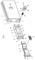
- An undercut longitudinal groove 2 is arranged in a first profile piece 1 and is delimited by lips 3.
- a bearing member 7 designed as a housing 6 and a holding member 8 inserted into the housing 6 are inserted in the hollow profile 5.
- the holding member 8 is designed as a folded and multi-cranked leaf spring 9.
- the free ends 10 of the leaf spring 9 are resilient in the transverse direction with a distance S parallel to each other and T-shaped in plan.
- the T-shaped ends 10 are extended over the width of the housing 8 and have bead-like formations 11 running transversely on the outer sides.
- the sides of the formations 11 facing the housing 8 are designed as vertical contact surfaces 12 which, as can be seen in FIG. 1, bear against the lips 3 of the longitudinal groove 2.
- the formations 11 can be formed, for example, by simply embossing the ends 10 of the leaf spring 9.
- the leaf spring 9 also has a centrally arranged, rectangular recess 13 and a round bore 14 which is arranged at the end opposite the free ends 10.
- a compression spring 15 is inserted into the rectangular recess 13 before the leaf spring 9 is inserted into the housing 6.
- a side wall 16 of the housing 6 is designed step-like in such a way that the multi-cranked leaf spring 9 lies flush against this side wall 16.
- guides 18 formed like blind holes are formed in side walls 16 and 17 of the housing 6.
- spacers 21 are arranged centrally on an upper part 19 and a lower part.
- the spacers are L-shaped and point away from the housing 6 with their free ends.
- the width of the spacers 21 is dimensioned such that it corresponds to the distance S between the free ends 10 of the leaf spring 9, so that the spacers 21 lie exactly between the free ends 10 of the leaf spring 9 when the leaf spring 9 is fully inserted into the housing 6 is.
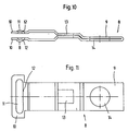
- the side wall 17 of the housing 6 has a bore 22 for receiving an eccentric 23.
- the eccentric 23 shown in Fig. 4 consists of two coaxially spaced disks 24 and 25 which are connected to each other via an eccentrically arranged, cylindrical part 26.
- a cam 27 is formed on the underside of the smaller disk 25 as a rotation limitation.
- the bore 22 in the side wall 17 of the housing 6 and the bore 14 of the leaf spring 9 are arranged coaxially to one another when the leaf spring 9 is inserted into the housing 6 until the free ends 10 abut the upper part 19 or lower part 20.
- the side wall 16 has an indentation 28 on the inside relative to the bore 22.
- the bore 22, the bore 14 and the recess 28 serve to receive the eccentric 23.
- the eccentric 23 is inserted with the smaller disk 25 first into the housing 6 with the leaf spring 9 on the inside when the leaf spring 9 is fully inserted into the housing 6. Due to the spring force of the compression spring 15 inserted into the leaf spring 9, the leaf spring tends to emerge from the front of the housing 6.
- the side wall bores the bore 14 against the eccentrically arranged cylinder 26 of the eccentric 23 and thus prevents the eccentric 23 from being pulled out of the housing 6 or the leaf spring 9 again.
- This jamming of the eccentric 23 by the leaf spring 9 is particularly important since a compression spring 30 is arranged in a bore 29 of the disk 25, which presses the eccentric outwards from the housing 6.
- the molded on the disc 25 as a rotation limit cam 27 serves to determine the eccentric positions "open” and "closed”. At the end points of the eccentric rotation range, the cam 27 runs onto a stop 31 in the recess 28.
- the eccentric 23 is pressed into the housing 6 against the force of the compression spring 30 and then the housing 6 is pushed into the hollow profile 5 of the profile piece 4. So that the eccentric 23 can be pressed completely into the housing 6, the side wall 16 of the housing 6 has the recess 28, which serves to receive the cam 27.
- the housing 6 is pushed into the hollow profile 5 until the disk 24 of the eccentric 23 is pressed out of the housing 6 by the force of the compression spring 30 in the opening 33 of the profile piece 4.
- the disc 24 of the eccentric 23 thus fixes the position of the housing 6 in the hollow profile 5 of the profile piece 4th
- the housing 6, leaf spring 9 and eccentric 23 are assembled in the manner described and inserted into the hollow profile 5 of the profile piece 4.
- the eccentric 23 is then turned to the "open" position.
- the leaf spring 9 is pushed out of the housing 6 by the compression spring 15 so far that the free ends 10 of the leaf spring 9 protrude in the longitudinal direction over the spacers 21.
- the free ends 10 of the leaf spring 9 can now be compressed in front of the spacers 21 against the spring force of the leaf spring 9.
- the free ends 10 of the leaf spring 9 protruding from the hollow profile 5 of the profile piece 4 are now pressed into the longitudinal groove 2 of the profile piece 1.
- the stop 31 is located in the recess 28 in the side wall 16 of the housing 6. This is formed, for example, in the lower region on the side wall of the recess 28.
- the eccentric can now only be rotated from one end position to the other, as a result of which the holding member positions are exactly defined.
Landscapes
- Engineering & Computer Science (AREA)
- General Engineering & Computer Science (AREA)
- Mechanical Engineering (AREA)
- Mechanical Coupling Of Light Guides (AREA)
- Surgical Instruments (AREA)
- Quick-Acting Or Multi-Walled Pipe Joints (AREA)
- Snaps, Bayonet Connections, Set Pins, And Snap Rings (AREA)
- Mutual Connection Of Rods And Tubes (AREA)
- Lining And Supports For Tunnels (AREA)
- Clamps And Clips (AREA)
- Massaging Devices (AREA)
Applications Claiming Priority (6)
| Application Number | Priority Date | Filing Date | Title |
|---|---|---|---|
| DE19924239199 DE4239199C2 (de) | 1992-11-21 | 1992-11-21 | Klemmverbindung |
| DE4239199 | 1992-11-21 | ||
| DE9311973U | 1993-08-11 | ||
| DE19934326925 DE4326925A1 (de) | 1993-08-11 | 1993-08-11 | Verbindungselement |
| DE9311973U DE9311973U1 (de) | 1992-11-21 | 1993-08-11 | Verbindungselement |
| DE4326925 | 1993-08-11 |
Publications (2)
| Publication Number | Publication Date |
|---|---|
| EP0599178A1 true EP0599178A1 (fr) | 1994-06-01 |
| EP0599178B1 EP0599178B1 (fr) | 1997-03-26 |
Family
ID=27204473
Family Applications (1)
| Application Number | Title | Priority Date | Filing Date |
|---|---|---|---|
| EP93118472A Expired - Lifetime EP0599178B1 (fr) | 1992-11-21 | 1993-11-16 | Elément de connexion |
Country Status (6)
| Country | Link |
|---|---|
| EP (1) | EP0599178B1 (fr) |
| AT (1) | ATE150848T1 (fr) |
| AU (1) | AU663024B2 (fr) |
| DE (1) | DE59305953D1 (fr) |
| ES (1) | ES2101926T3 (fr) |
| WO (1) | WO1994012796A1 (fr) |
Cited By (6)
| Publication number | Priority date | Publication date | Assignee | Title |
|---|---|---|---|---|
| WO1999009326A1 (fr) * | 1997-08-12 | 1999-02-25 | Syma Intercontinental Ag | Douille de fermeture pour un dispositif de serrage utilise pour assembler de facon liberable deux pieces profilees |
| EP1211428A1 (fr) * | 2000-11-27 | 2002-06-05 | M.F. Metal Forniture Srl | Structure pour mobilier démontable en tubes et méthode d'assemblage |
| DE102009012286A1 (de) | 2008-04-05 | 2009-10-08 | Patea Gmbh | Verbindungsvorrichtung für die lösbare Verbindung zweier Gegenstände |
| DE102014104413A1 (de) | 2014-03-28 | 2015-10-01 | Hestex Systems B.V. | Verbinder |
| US9476441B2 (en) | 2012-07-09 | 2016-10-25 | Syma Intercontinental Ag | Clamping device for the releasable connection of two profile sections |
| CN107885747A (zh) * | 2016-09-29 | 2018-04-06 | 西门子公司 | 一种语义关系生成方法和设备 |
Families Citing this family (1)
| Publication number | Priority date | Publication date | Assignee | Title |
|---|---|---|---|---|
| AT509578B1 (de) * | 2010-01-29 | 2015-05-15 | Stumpfl Reinhold | Projektions- oder präsentationswand |
Citations (4)
| Publication number | Priority date | Publication date | Assignee | Title |
|---|---|---|---|---|
| EP0166794A1 (fr) * | 1984-07-02 | 1986-01-08 | Gebrüder Vieler GmbH | Dispositif pour la connexion des barres profilées d'une étagère |
| DE3607849C1 (de) * | 1986-03-10 | 1987-08-13 | Connec Ag | Befestigungsvorrichtung mit einem Klemmverschluss zum Ioesbaren Angreifen an Hinterschneidungen aufweisenden Profilen od.dgl. |
| DE3821625A1 (de) * | 1988-06-27 | 1989-12-28 | Kluge Dr Heinz Nachf | Spannverschluss |
| DE9106365U1 (de) * | 1991-05-23 | 1991-07-11 | Renken, Uwe Wilhelm, 5047 Wesseling | Spannschloß zur lösbaren Verbindung von Profilstangen |
Family Cites Families (1)
| Publication number | Priority date | Publication date | Assignee | Title |
|---|---|---|---|---|
| GB1088133A (en) * | 1965-05-07 | 1967-10-25 | Versatile Fittings W H S Ltd | Improvements relating to hollow tubes |
-
1993
- 1993-11-16 AT AT93118472T patent/ATE150848T1/de not_active IP Right Cessation
- 1993-11-16 ES ES93118472T patent/ES2101926T3/es not_active Expired - Lifetime
- 1993-11-16 EP EP93118472A patent/EP0599178B1/fr not_active Expired - Lifetime
- 1993-11-16 DE DE59305953T patent/DE59305953D1/de not_active Expired - Fee Related
- 1993-11-20 WO PCT/EP1993/003248 patent/WO1994012796A1/fr not_active Ceased
- 1993-11-20 AU AU56257/94A patent/AU663024B2/en not_active Ceased
Patent Citations (5)
| Publication number | Priority date | Publication date | Assignee | Title |
|---|---|---|---|---|
| EP0166794A1 (fr) * | 1984-07-02 | 1986-01-08 | Gebrüder Vieler GmbH | Dispositif pour la connexion des barres profilées d'une étagère |
| DE3607849C1 (de) * | 1986-03-10 | 1987-08-13 | Connec Ag | Befestigungsvorrichtung mit einem Klemmverschluss zum Ioesbaren Angreifen an Hinterschneidungen aufweisenden Profilen od.dgl. |
| EP0238848A2 (fr) * | 1986-03-10 | 1987-09-30 | Connec AG Systembau-Technik | Dispositif de fixation ayant une fermeture de serrage pour l'attachement amovible à des profils ayant des contre de pouilles |
| DE3821625A1 (de) * | 1988-06-27 | 1989-12-28 | Kluge Dr Heinz Nachf | Spannverschluss |
| DE9106365U1 (de) * | 1991-05-23 | 1991-07-11 | Renken, Uwe Wilhelm, 5047 Wesseling | Spannschloß zur lösbaren Verbindung von Profilstangen |
Cited By (7)
| Publication number | Priority date | Publication date | Assignee | Title |
|---|---|---|---|---|
| WO1999009326A1 (fr) * | 1997-08-12 | 1999-02-25 | Syma Intercontinental Ag | Douille de fermeture pour un dispositif de serrage utilise pour assembler de facon liberable deux pieces profilees |
| US6334732B1 (en) | 1997-08-12 | 2002-01-01 | Syma Intercontinental Ag | Closing bushing for a clamping device used for removably connecting two profiled parts |
| EP1211428A1 (fr) * | 2000-11-27 | 2002-06-05 | M.F. Metal Forniture Srl | Structure pour mobilier démontable en tubes et méthode d'assemblage |
| DE102009012286A1 (de) | 2008-04-05 | 2009-10-08 | Patea Gmbh | Verbindungsvorrichtung für die lösbare Verbindung zweier Gegenstände |
| US9476441B2 (en) | 2012-07-09 | 2016-10-25 | Syma Intercontinental Ag | Clamping device for the releasable connection of two profile sections |
| DE102014104413A1 (de) | 2014-03-28 | 2015-10-01 | Hestex Systems B.V. | Verbinder |
| CN107885747A (zh) * | 2016-09-29 | 2018-04-06 | 西门子公司 | 一种语义关系生成方法和设备 |
Also Published As
| Publication number | Publication date |
|---|---|
| AU5625794A (en) | 1994-06-22 |
| WO1994012796A1 (fr) | 1994-06-09 |
| DE59305953D1 (de) | 1997-04-30 |
| ATE150848T1 (de) | 1997-04-15 |
| ES2101926T3 (es) | 1997-07-16 |
| AU663024B2 (en) | 1995-09-21 |
| EP0599178B1 (fr) | 1997-03-26 |
Similar Documents
| Publication | Publication Date | Title |
|---|---|---|
| DE69216665T2 (de) | Zylinderschloss | |
| EP1588007B1 (fr) | Dispositif de retenue de porte | |
| EP1588006B1 (fr) | Dispositif de blocage de porte | |
| DE2610200B2 (de) | Beschlag zum lösbaren Verbinden zweier Bauteile, insbesondere von plat' tenförmigen Bauteilen für Möbel | |
| DE4132447A1 (de) | Anordnung zur erstellung von wand- und/oder deckenkonstruktionen, insbesondere im messebau | |
| EP1008767A1 (fr) | Système de fixation pour panneaux d'ameublement | |
| EP1332702A2 (fr) | Support pour fixer des éléments sous forme de barres | |
| EP0599178B1 (fr) | Elément de connexion | |
| DE3924547C2 (fr) | ||
| DE10220879A1 (de) | Ständer zum Aufspannen von stabförmigen Teilen | |
| DE68903447T2 (de) | Sicherheitszylinder fuer ein schloss und entsprechender schluessel. | |
| DE3036560A1 (de) | Beschlag zur herstellung einer loesbaren verbindung zwischen teilen, insbesondere moebelteile wie tischelemente | |
| DE102008018692B3 (de) | Eckverbindung für Bettgestelle, die insbesondere metallfrei sind | |
| DE202008005295U1 (de) | Verbindung | |
| DE29505752U1 (de) | Vorrichtung zum Verbinden von Platten mittels Verschraubung | |
| DE102013012232A1 (de) | Hebelgriff | |
| DE9311973U1 (de) | Verbindungselement | |
| EP0371237A2 (fr) | Jeu de pièces détachées pour un châssis de porte | |
| DE4326925A1 (de) | Verbindungselement | |
| DE4239199C2 (de) | Klemmverbindung | |
| DE3721483C2 (fr) | ||
| DE202011000950U1 (de) | System zur Befestigung eines Beschlagteils | |
| EP1749953A2 (fr) | Carré de poignée à serrage | |
| AT403192B (de) | Verbindungsbeschlag zum lösbaren verbinden zweier möbelteile | |
| EP1141506B1 (fr) | Battant de fenetre ou de porte |
Legal Events
| Date | Code | Title | Description |
|---|---|---|---|
| PUAI | Public reference made under article 153(3) epc to a published international application that has entered the european phase |
Free format text: ORIGINAL CODE: 0009012 |
|
| AK | Designated contracting states |
Kind code of ref document: A1 Designated state(s): AT BE CH DE ES FR GB LI NL SE |
|
| 17P | Request for examination filed |
Effective date: 19941125 |
|
| 17Q | First examination report despatched |
Effective date: 19951221 |
|
| GRAG | Despatch of communication of intention to grant |
Free format text: ORIGINAL CODE: EPIDOS AGRA |
|
| GRAH | Despatch of communication of intention to grant a patent |
Free format text: ORIGINAL CODE: EPIDOS IGRA |
|
| GRAH | Despatch of communication of intention to grant a patent |
Free format text: ORIGINAL CODE: EPIDOS IGRA |
|
| GRAA | (expected) grant |
Free format text: ORIGINAL CODE: 0009210 |
|
| AK | Designated contracting states |
Kind code of ref document: B1 Designated state(s): AT BE CH DE ES FR GB LI NL SE |
|
| REF | Corresponds to: |
Ref document number: 150848 Country of ref document: AT Date of ref document: 19970415 Kind code of ref document: T |
|
| REG | Reference to a national code |
Ref country code: CH Ref legal event code: EP |
|
| REF | Corresponds to: |
Ref document number: 59305953 Country of ref document: DE Date of ref document: 19970430 |
|
| REG | Reference to a national code |
Ref country code: CH Ref legal event code: NV Representative=s name: E. BLUM & CO. PATENTANWAELTE |
|
| ET | Fr: translation filed | ||
| GBT | Gb: translation of ep patent filed (gb section 77(6)(a)/1977) |
Effective date: 19970604 |
|
| REG | Reference to a national code |
Ref country code: ES Ref legal event code: FG2A Ref document number: 2101926 Country of ref document: ES Kind code of ref document: T3 |
|
| PLBE | No opposition filed within time limit |
Free format text: ORIGINAL CODE: 0009261 |
|
| STAA | Information on the status of an ep patent application or granted ep patent |
Free format text: STATUS: NO OPPOSITION FILED WITHIN TIME LIMIT |
|
| 26N | No opposition filed | ||
| PGFP | Annual fee paid to national office [announced via postgrant information from national office to epo] |
Ref country code: FR Payment date: 19980917 Year of fee payment: 6 |
|
| PGFP | Annual fee paid to national office [announced via postgrant information from national office to epo] |
Ref country code: AT Payment date: 19981119 Year of fee payment: 6 |
|
| PGFP | Annual fee paid to national office [announced via postgrant information from national office to epo] |
Ref country code: ES Payment date: 19981123 Year of fee payment: 6 |
|
| PG25 | Lapsed in a contracting state [announced via postgrant information from national office to epo] |
Ref country code: AT Free format text: LAPSE BECAUSE OF NON-PAYMENT OF DUE FEES Effective date: 19991116 |
|
| PG25 | Lapsed in a contracting state [announced via postgrant information from national office to epo] |
Ref country code: ES Free format text: LAPSE BECAUSE OF NON-PAYMENT OF DUE FEES Effective date: 19991117 |
|
| PG25 | Lapsed in a contracting state [announced via postgrant information from national office to epo] |
Ref country code: FR Free format text: LAPSE BECAUSE OF NON-PAYMENT OF DUE FEES Effective date: 20000731 |
|
| REG | Reference to a national code |
Ref country code: FR Ref legal event code: ST |
|
| PGFP | Annual fee paid to national office [announced via postgrant information from national office to epo] |
Ref country code: GB Payment date: 20001013 Year of fee payment: 8 |
|
| PGFP | Annual fee paid to national office [announced via postgrant information from national office to epo] |
Ref country code: CH Payment date: 20001016 Year of fee payment: 8 |
|
| PGFP | Annual fee paid to national office [announced via postgrant information from national office to epo] |
Ref country code: NL Payment date: 20001026 Year of fee payment: 8 |
|
| PGFP | Annual fee paid to national office [announced via postgrant information from national office to epo] |
Ref country code: SE Payment date: 20001030 Year of fee payment: 8 |
|
| PGFP | Annual fee paid to national office [announced via postgrant information from national office to epo] |
Ref country code: BE Payment date: 20001116 Year of fee payment: 8 |
|
| PGFP | Annual fee paid to national office [announced via postgrant information from national office to epo] |
Ref country code: DE Payment date: 20010119 Year of fee payment: 8 |
|
| PG25 | Lapsed in a contracting state [announced via postgrant information from national office to epo] |
Ref country code: GB Free format text: LAPSE BECAUSE OF NON-PAYMENT OF DUE FEES Effective date: 20011116 |
|
| PG25 | Lapsed in a contracting state [announced via postgrant information from national office to epo] |
Ref country code: SE Free format text: LAPSE BECAUSE OF NON-PAYMENT OF DUE FEES Effective date: 20011117 |
|
| PG25 | Lapsed in a contracting state [announced via postgrant information from national office to epo] |
Ref country code: LI Free format text: LAPSE BECAUSE OF NON-PAYMENT OF DUE FEES Effective date: 20011130 Ref country code: CH Free format text: LAPSE BECAUSE OF NON-PAYMENT OF DUE FEES Effective date: 20011130 Ref country code: BE Free format text: LAPSE BECAUSE OF NON-PAYMENT OF DUE FEES Effective date: 20011130 |
|
| REG | Reference to a national code |
Ref country code: GB Ref legal event code: IF02 |
|
| BERE | Be: lapsed |
Owner name: HESTEX SYSTEMS B.V. Effective date: 20011130 |
|
| PG25 | Lapsed in a contracting state [announced via postgrant information from national office to epo] |
Ref country code: NL Free format text: LAPSE BECAUSE OF NON-PAYMENT OF DUE FEES Effective date: 20020601 |
|
| EUG | Se: european patent has lapsed |
Ref document number: 93118472.5 |
|
| PG25 | Lapsed in a contracting state [announced via postgrant information from national office to epo] |
Ref country code: DE Free format text: LAPSE BECAUSE OF NON-PAYMENT OF DUE FEES Effective date: 20020702 |
|
| REG | Reference to a national code |
Ref country code: CH Ref legal event code: PL |
|
| NLV4 | Nl: lapsed or anulled due to non-payment of the annual fee |
Effective date: 20020601 |
|
| REG | Reference to a national code |
Ref country code: ES Ref legal event code: FD2A Effective date: 20001214 |