EP1008767A1 - Système de fixation pour panneaux d'ameublement - Google Patents
Système de fixation pour panneaux d'ameublement Download PDFInfo
- Publication number
- EP1008767A1 EP1008767A1 EP99123537A EP99123537A EP1008767A1 EP 1008767 A1 EP1008767 A1 EP 1008767A1 EP 99123537 A EP99123537 A EP 99123537A EP 99123537 A EP99123537 A EP 99123537A EP 1008767 A1 EP1008767 A1 EP 1008767A1
- Authority
- EP
- European Patent Office
- Prior art keywords
- dowel
- plate
- halves
- clamp
- fork
- Prior art date
- Legal status (The legal status is an assumption and is not a legal conclusion. Google has not performed a legal analysis and makes no representation as to the accuracy of the status listed.)
- Withdrawn
Links
- 230000000295 complement effect Effects 0.000 claims description 3
- 230000000694 effects Effects 0.000 description 2
- 238000011161 development Methods 0.000 description 1
- 230000018109 developmental process Effects 0.000 description 1
- 238000005553 drilling Methods 0.000 description 1
- 230000007257 malfunction Effects 0.000 description 1
- 238000004806 packaging method and process Methods 0.000 description 1
- 238000007781 pre-processing Methods 0.000 description 1
- 230000000750 progressive effect Effects 0.000 description 1
Images

Classifications
-
- F—MECHANICAL ENGINEERING; LIGHTING; HEATING; WEAPONS; BLASTING
- F16—ENGINEERING ELEMENTS AND UNITS; GENERAL MEASURES FOR PRODUCING AND MAINTAINING EFFECTIVE FUNCTIONING OF MACHINES OR INSTALLATIONS; THERMAL INSULATION IN GENERAL
- F16B—DEVICES FOR FASTENING OR SECURING CONSTRUCTIONAL ELEMENTS OR MACHINE PARTS TOGETHER, e.g. NAILS, BOLTS, CIRCLIPS, CLAMPS, CLIPS OR WEDGES; JOINTS OR JOINTING
- F16B12/00—Jointing of furniture or the like, e.g. hidden from exterior
- F16B12/10—Jointing of furniture or the like, e.g. hidden from exterior using pegs, bolts, tenons, clamps, clips, or the like
- F16B12/12—Jointing of furniture or the like, e.g. hidden from exterior using pegs, bolts, tenons, clamps, clips, or the like for non-metal furniture parts, e.g. made of wood, of plastics
- F16B12/20—Jointing of furniture or the like, e.g. hidden from exterior using pegs, bolts, tenons, clamps, clips, or the like for non-metal furniture parts, e.g. made of wood, of plastics using clamps, clips, wedges, sliding bolts, or the like
- F16B12/2009—Jointing of furniture or the like, e.g. hidden from exterior using pegs, bolts, tenons, clamps, clips, or the like for non-metal furniture parts, e.g. made of wood, of plastics using clamps, clips, wedges, sliding bolts, or the like actuated by rotary motion
- F16B12/2027—Jointing of furniture or the like, e.g. hidden from exterior using pegs, bolts, tenons, clamps, clips, or the like for non-metal furniture parts, e.g. made of wood, of plastics using clamps, clips, wedges, sliding bolts, or the like actuated by rotary motion with rotating excenters or wedges
- F16B12/2036—Jointing of furniture or the like, e.g. hidden from exterior using pegs, bolts, tenons, clamps, clips, or the like for non-metal furniture parts, e.g. made of wood, of plastics using clamps, clips, wedges, sliding bolts, or the like actuated by rotary motion with rotating excenters or wedges with rotating excenters or wedges acting on a head of a pin or screw
-
- F—MECHANICAL ENGINEERING; LIGHTING; HEATING; WEAPONS; BLASTING
- F16—ENGINEERING ELEMENTS AND UNITS; GENERAL MEASURES FOR PRODUCING AND MAINTAINING EFFECTIVE FUNCTIONING OF MACHINES OR INSTALLATIONS; THERMAL INSULATION IN GENERAL
- F16B—DEVICES FOR FASTENING OR SECURING CONSTRUCTIONAL ELEMENTS OR MACHINE PARTS TOGETHER, e.g. NAILS, BOLTS, CIRCLIPS, CLAMPS, CLIPS OR WEDGES; JOINTS OR JOINTING
- F16B12/00—Jointing of furniture or the like, e.g. hidden from exterior
- F16B12/44—Leg joints; Corner joints
- F16B12/46—Non-metal corner connections
-
- F—MECHANICAL ENGINEERING; LIGHTING; HEATING; WEAPONS; BLASTING
- F16—ENGINEERING ELEMENTS AND UNITS; GENERAL MEASURES FOR PRODUCING AND MAINTAINING EFFECTIVE FUNCTIONING OF MACHINES OR INSTALLATIONS; THERMAL INSULATION IN GENERAL
- F16B—DEVICES FOR FASTENING OR SECURING CONSTRUCTIONAL ELEMENTS OR MACHINE PARTS TOGETHER, e.g. NAILS, BOLTS, CIRCLIPS, CLAMPS, CLIPS OR WEDGES; JOINTS OR JOINTING
- F16B12/00—Jointing of furniture or the like, e.g. hidden from exterior
- F16B12/10—Jointing of furniture or the like, e.g. hidden from exterior using pegs, bolts, tenons, clamps, clips, or the like
- F16B2012/106—Connection bolts for connection fittings
Definitions
- the invention relates to a connecting device for plates in the Preamble of claim 1 mentioned type.
- the device forming the subject of the present invention is one Device for the simple connection of two plates in mutually perpendicular Levels is used, this connection between a surface of one Plate and one edge of the other plate is done.
- the rod is tightened by turning a toggle in the Clamping device is arranged and progressive in its clamping rotation exerts greater traction.
- the rotating knob has a long groove which is open from its tip and into which a narrowed neck engages, which at the Rod is formed. In both embodiments, the increasing results Traction from a cam profile, which is formed in the rotatable knob.
- a major disadvantage of these known devices is that the first plate anchored rod complicates the storage and transportation of the parts, because direct contact with other plates is prevented. Furthermore, the Pole clearly recognizes the risk of damage to other parts and people, being a blow to other elements continues to anchor the actual Pole can affect and can lead to this when exercising Pulling force when connecting to the other plate releases.
- the invention has for its object a connection device of the beginning to create mentioned type that has a simple structure and even in pre-assembled condition none from a main or side surface of the panels protruding parts, and the preprocessing of the plates is easy.
- the device according to the invention is based on a new concept of the components and functionality, whereby the peculiarity arises that in the main or Side surface of the first plate, a blind bore is provided, into which expandable dowel is used, while this is not in the spread Condition.
- the dowel is axially displaceable in a clamping device mounted, which is inserted into a receiving seat formed in the second plate, the side with the connecting edge formed by the end face of the second Plate is connected via a side opening from which this expandable Dowel protrudes.
- the dowel is divided into two halves in the axial direction are connected to each other via respective legs of a fork-shaped end, the is inserted in the longitudinal direction in a radial guide of the clamping device.
- This End is provided with a hole in which an eccentric cylindrical section can be used, which starts from an actuating spindle which extends in the axial direction extends with respect to the clamping device and is rotatably mounted therein.
- the Actuating spindle has respective actuating notches for the on its end faces Tip of a screwdriver, these slots from the side surfaces of the Clamping device are accessible from the mouth or the bottom of the receiving seat are arranged.
- the tensioning device has respective sides radial wedges on through the side opening in the connecting edge of the second Project out plate and are in the axial plane that the expandable Dowels divided, with a wedge for each side of the forked end.
- These radial wedges advantageously have a larger width than that Distance between the two halves of the expandable dowel is not in it expanded state, and the radial wedges can not be expanded in this Condition to enter respective complementary and reciprocal grooves that are in halves of the expandable dowel are formed.
- This device according to the invention does not require a preassembled rod in the first Plate, and a simple blind hole in this plate is sufficient. Accordingly there is the problem of malfunction and risk of damage due to this rod does not.
- the first plate enables full-surface contact with other plates, which means that Packaging and storage is facilitated without a There is a risk of damage.
- the arrangement leads to a simple Blind drilling for faster, easier and more economical assembly than that known rod.
- the operation with the device according to the invention is enormous simple, fast and leads to high reliability. It is enough the divided insert expandable dowels into the blind hole (the first plate), followed by a rotation of the operating spindle the effect of the eccentric cylindrical Section on the fork-shaped end causes this along the radial Leadership occurs, and as soon as this movement begins, the wedges call the spread of the expandable dowel, making it more and more in the blind hole is set, which is the desired attachment between the first and second plates results.
- the radial wedges of the clamping device have an inclined tip Section that merges into a straight part behind it, the one Core with essentially parallel side walls results.
- the one for attachment serving expansion of the dowel by the inclined section of the radial Wedges are created while sliding along the straight line Section maintained with a corresponding pulling action that the plates approximated and attached to each other.
- the two halves of the expandable dowels on the circumference of a plurality of semi-annular teeth.
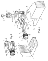
- Figure 2 the relates to a connecting device for panels of furniture of the type which for the convenient connection of two plates, namely a first plate 1 and a second plate 2, are determined perpendicular to each other, this connection between a side surface of, for example, the first plate 1 and the edge
- the second plate 2 takes place in which a clamping device Connection of the plates 1, 2 is installed, through a side surface of the second Plate 2 is inserted through in a receiving seat 6, the side with a adjacent edge is connected via which the connection to the first plate 1 is done.
- this receiving seat extends 6 through a side surface of the plate 2 perpendicular into this plate, the Receiving seat drilled or at such a distance from the connecting edge is produced in such a way that at the same time the lateral opening 6a in the Connecting edge results.
- the first is in the side surface (FIG. 1) Plate 1 only a blind hole 3 is provided, in which an expandable dowel 4th can be used in its non-spread state.
- This dowel is axial Slidability mounted in a clamping device 5, which is in the receiving seat 6 is used, the side with the connecting edge of the second plate 2 on the lateral opening 6a communicates through which the expandable dowel 4 protrudes.
- the expandable dowel 4 is divided in the axial direction into two halves, which are together are connected via respective legs of a fork-shaped end 7, which in Longitudinal direction in a radial guide 8 of the clamping device 5 is arranged.
- the two halves of the dowel 4 are at the free ends of the legs of the attached fork-shaped end 7 or integrally formed therewith.
- connection area of the fork-shaped end opposite the dowel 4 7 is provided with a bore 9 into which an eccentric cylindrical section 10 is used, which starts from an actuating spindle 11 which extends in the axial direction extends relative to the clamping device 5 and is rotatably mounted therein.
- the Actuating spindle has respective end faces located at the end Actuation slots for the tip of a screwdriver 12 on the Surfaces of the clamping device 5 are accessible, which are adjacent to the mouth or are arranged to the bottom of the receiving seat 6.
- the clamping device 5 has respective radial wedges 13 on the side, which through the Project a lateral opening 6a in the edge of the second plate 2 and are in the axial plane that divides the expandable dowel 4, wherein there is a wedge on each side of the fork-shaped end 7 (above or below this end).
- the radial wedges 13 have a width that in is expediently greater than the distance which is in the non-spread state exists between the halves of the expandable dowel 4.
- These radial wedges 13 can in the non-spread state between the respective complementary and Reciprocal grooves 14 are arranged in the two halves of the expandable Dowels 4 are formed.
- the radial wedges 13 of the clamping device 5 have an inclined tip Section 13a, which continues in a rectilinear rear part 13b, the one Forms core with essentially parallel side walls. Spreading to Clamping of the dowel 4 through the inclined section 13a of the radial Wedges 13 is created while sliding along the straight line Section 13b maintained, with a corresponding tensile effect that the Plates 1 and 2 approximate and hold to each other.
- the operational use of the novel device is in Figures 3 and 4, while the mode of operation is shown in FIG. 7.
- the expandable dowel 4 is (in its non-spread state) in the blind hole 3 of the first plate 1 used ( Figures 3 and 4) after the device in the receiving seat 6 of second plate 2 was installed.
- the secret of the simple and effective connection device is based on the special configuration of the unit ( Figures 5 and 6) by the expandable dowel 4 and the fork-shaped end 7 is formed.
- the two halves of the Expandable dowels 4 have a plurality of semi-annular teeth on their circumference 15 on.
Landscapes
- Engineering & Computer Science (AREA)
- General Engineering & Computer Science (AREA)
- Mechanical Engineering (AREA)
- Joining Of Building Structures In Genera (AREA)
- Furniture Connections (AREA)
Applications Claiming Priority (2)
| Application Number | Priority Date | Filing Date | Title |
|---|---|---|---|
| ES9802564 | 1998-12-09 | ||
| ES9802564A ES2221492B1 (es) | 1998-12-09 | 1998-12-09 | Dispositivo perfeccionado para ensamble de paneles de muebles. |
Publications (1)
| Publication Number | Publication Date |
|---|---|
| EP1008767A1 true EP1008767A1 (fr) | 2000-06-14 |
Family
ID=8306037
Family Applications (1)
| Application Number | Title | Priority Date | Filing Date |
|---|---|---|---|
| EP99123537A Withdrawn EP1008767A1 (fr) | 1998-12-09 | 1999-11-26 | Système de fixation pour panneaux d'ameublement |
Country Status (2)
| Country | Link |
|---|---|
| EP (1) | EP1008767A1 (fr) |
| ES (1) | ES2221492B1 (fr) |
Cited By (18)
| Publication number | Priority date | Publication date | Assignee | Title |
|---|---|---|---|---|
| DE20004067U1 (de) | 2000-03-03 | 2000-06-21 | Huwil-Werke GmbH Möbelschloß- und Beschlagfabriken, 53809 Ruppichteroth | Beschlag zum lösbaren Verbinden zweier aufeinanderstoßender Bauteile für Möbel |
| WO2002035102A1 (fr) * | 2000-10-25 | 2002-05-02 | 154322 Canada Inc. | Chevillage intégré pour le montage de meubles |
| EP1530926A2 (fr) | 2003-11-14 | 2005-05-18 | Ferramenta Livenza S.r.l. | Arrangement amélioré de support d'étagère |
| EP1686269A1 (fr) * | 2005-01-29 | 2006-08-02 | Häfele GmbH & Co. KG | Connecteur pour panneaux, en particulier pour planches d'étagère |
| EP1624198A3 (fr) * | 2004-08-06 | 2007-01-24 | Häfele GmbH & Co. KG | Ferrrure d'assemblage pour panneaux, notamment pour planches d'étagères |
| EP1860331A1 (fr) * | 2006-05-24 | 2007-11-28 | Festool GmbH | Dispositif d'armature destiné à relier deux parties d'un meuble |
| DE202007000439U1 (de) * | 2007-01-05 | 2008-05-15 | Hettich-Heinze Gmbh & Co Kg | Verbindungsbeschlag zum Verbinden zweier Möbelplatten |
| DE102009011845A1 (de) * | 2009-03-05 | 2010-09-16 | Festool Gmbh | Verbindungsbeschlag |
| CN101449066B (zh) * | 2006-05-18 | 2011-02-16 | Rk知识产权(股份)有限公司 | 用于板条或板条状部件的连接器 |
| DE202009016669U1 (de) * | 2009-12-10 | 2011-04-21 | Grass Gmbh | Möbel, Möbelteil und Vorrichtung zur Verbindung eines Frontbauteils eines Möbelteils |
| DE202011100715U1 (de) | 2010-07-26 | 2011-07-12 | Julius Blum Gmbh | Möbelbeschlag |
| AT509227A4 (de) * | 2010-07-26 | 2011-07-15 | Blum Gmbh Julius | Möbelbeschlag |
| ITMI20110191A1 (it) * | 2011-02-09 | 2012-08-10 | O M M S A S Di Ing Roberto Natal E Mariani & C | Dispositivo di giunzione di pannelli di un mobile |
| EP2808566A1 (fr) * | 2013-05-31 | 2014-12-03 | Häfele GmbH & Co. KG | Cheville à expansion |
| CN108223525A (zh) * | 2018-02-09 | 2018-06-29 | 宁波柏厨集成厨房有限公司 | 一种活动直角码 |
| EP3382213A1 (fr) | 2017-03-31 | 2018-10-03 | Royo Spain, S.L. | Raccord de fixation de panneau |
| US11143225B2 (en) * | 2019-03-14 | 2021-10-12 | Ju-Chiung Tseng | Connecting structure for assembly and assembled apparatus using the same |
| WO2025223575A1 (fr) * | 2024-04-23 | 2025-10-30 | 精诺科技研究(广东)有限公司 | Connecteur, ensemble de connexion et système de connexion |
Citations (3)
| Publication number | Priority date | Publication date | Assignee | Title |
|---|---|---|---|---|
| DE2610200A1 (de) * | 1976-03-11 | 1977-09-15 | Heinze Fa R | Beschlag zum loesbaren verbinden von bauteilen, insbesondere zum wieder loesbaren verbinden von plattenfoermigen bauteilen |
| GB2040385A (en) * | 1977-10-27 | 1980-08-28 | Heinze Richard Gmbh Co Kg | Furniture connectors |
| US5676487A (en) * | 1994-11-04 | 1997-10-14 | Mepla-Werke Lautenschlager Gmbh & Co. Kg | Connecting hardware |
Family Cites Families (2)
| Publication number | Priority date | Publication date | Assignee | Title |
|---|---|---|---|---|
| DE2546526B2 (de) * | 1975-10-17 | 1980-05-08 | Richard Heinze Gmbh & Co Kg, 4900 Herford | Beschlag zum lösbaren Verbinden zweier senkrecht aufeinanderstoßender plattenförmiger Bauteile |
| IT1169586B (it) * | 1983-10-18 | 1987-06-03 | Giovannetti F | Dispositivo di fissaggio per unire tra loro pannelli in modo sbloccabile |
-
1998
- 1998-12-09 ES ES9802564A patent/ES2221492B1/es not_active Expired - Lifetime
-
1999
- 1999-11-26 EP EP99123537A patent/EP1008767A1/fr not_active Withdrawn
Patent Citations (3)
| Publication number | Priority date | Publication date | Assignee | Title |
|---|---|---|---|---|
| DE2610200A1 (de) * | 1976-03-11 | 1977-09-15 | Heinze Fa R | Beschlag zum loesbaren verbinden von bauteilen, insbesondere zum wieder loesbaren verbinden von plattenfoermigen bauteilen |
| GB2040385A (en) * | 1977-10-27 | 1980-08-28 | Heinze Richard Gmbh Co Kg | Furniture connectors |
| US5676487A (en) * | 1994-11-04 | 1997-10-14 | Mepla-Werke Lautenschlager Gmbh & Co. Kg | Connecting hardware |
Cited By (26)
| Publication number | Priority date | Publication date | Assignee | Title |
|---|---|---|---|---|
| DE20004067U1 (de) | 2000-03-03 | 2000-06-21 | Huwil-Werke GmbH Möbelschloß- und Beschlagfabriken, 53809 Ruppichteroth | Beschlag zum lösbaren Verbinden zweier aufeinanderstoßender Bauteile für Möbel |
| WO2002035102A1 (fr) * | 2000-10-25 | 2002-05-02 | 154322 Canada Inc. | Chevillage intégré pour le montage de meubles |
| US6908252B1 (en) | 2000-10-25 | 2005-06-21 | 154322 Canada Inc. | Integrated joint assembly fastener |
| EP1530926A2 (fr) | 2003-11-14 | 2005-05-18 | Ferramenta Livenza S.r.l. | Arrangement amélioré de support d'étagère |
| EP1624198A3 (fr) * | 2004-08-06 | 2007-01-24 | Häfele GmbH & Co. KG | Ferrrure d'assemblage pour panneaux, notamment pour planches d'étagères |
| US7578633B2 (en) | 2005-01-29 | 2009-08-25 | Häfele GmbH & Co. KG | Connector for plates, particularly for shelves or trays |
| RU2319044C2 (ru) * | 2005-01-29 | 2008-03-10 | Хефеле Гмбх Унд Ко Кг | Соединитель для плит, в частности двух плит, расположенных перпендикулярно друг другу |
| EP1686269A1 (fr) * | 2005-01-29 | 2006-08-02 | Häfele GmbH & Co. KG | Connecteur pour panneaux, en particulier pour planches d'étagère |
| CN101449066B (zh) * | 2006-05-18 | 2011-02-16 | Rk知识产权(股份)有限公司 | 用于板条或板条状部件的连接器 |
| EP1860331A1 (fr) * | 2006-05-24 | 2007-11-28 | Festool GmbH | Dispositif d'armature destiné à relier deux parties d'un meuble |
| DE202007000439U1 (de) * | 2007-01-05 | 2008-05-15 | Hettich-Heinze Gmbh & Co Kg | Verbindungsbeschlag zum Verbinden zweier Möbelplatten |
| DE102009011845B4 (de) * | 2009-03-05 | 2017-07-06 | Festool Gmbh | Verbindungsbeschlag |
| DE102009011845A1 (de) * | 2009-03-05 | 2010-09-16 | Festool Gmbh | Verbindungsbeschlag |
| DE202009016669U1 (de) * | 2009-12-10 | 2011-04-21 | Grass Gmbh | Möbel, Möbelteil und Vorrichtung zur Verbindung eines Frontbauteils eines Möbelteils |
| AT509227A4 (de) * | 2010-07-26 | 2011-07-15 | Blum Gmbh Julius | Möbelbeschlag |
| AT509227B1 (de) * | 2010-07-26 | 2011-07-15 | Blum Gmbh Julius | Möbelbeschlag |
| DE202011100715U1 (de) | 2010-07-26 | 2011-07-12 | Julius Blum Gmbh | Möbelbeschlag |
| ITMI20110191A1 (it) * | 2011-02-09 | 2012-08-10 | O M M S A S Di Ing Roberto Natal E Mariani & C | Dispositivo di giunzione di pannelli di un mobile |
| EP2487373A1 (fr) * | 2011-02-09 | 2012-08-15 | O.M.M. s.a.s. dell'Ing. Roberto Mariani & C. | Dispositif d'assemblage pour panneaux d'un meuble |
| EP2808566A1 (fr) * | 2013-05-31 | 2014-12-03 | Häfele GmbH & Co. KG | Cheville à expansion |
| US10161432B2 (en) | 2013-05-31 | 2018-12-25 | Häfele GmbH & Co. KG | Spreading connector |
| EP3382213A1 (fr) | 2017-03-31 | 2018-10-03 | Royo Spain, S.L. | Raccord de fixation de panneau |
| CN108223525A (zh) * | 2018-02-09 | 2018-06-29 | 宁波柏厨集成厨房有限公司 | 一种活动直角码 |
| CN108223525B (zh) * | 2018-02-09 | 2023-12-26 | 宁波柏厨集成厨房有限公司 | 一种活动直角码 |
| US11143225B2 (en) * | 2019-03-14 | 2021-10-12 | Ju-Chiung Tseng | Connecting structure for assembly and assembled apparatus using the same |
| WO2025223575A1 (fr) * | 2024-04-23 | 2025-10-30 | 精诺科技研究(广东)有限公司 | Connecteur, ensemble de connexion et système de connexion |
Also Published As
| Publication number | Publication date |
|---|---|
| ES2221492A1 (es) | 2004-12-16 |
| ES2221492B1 (es) | 2005-07-16 |
Similar Documents
| Publication | Publication Date | Title |
|---|---|---|
| EP1008767A1 (fr) | Système de fixation pour panneaux d'ameublement | |
| DE3416627C2 (fr) | ||
| DE9404642U1 (de) | Verbindungselement | |
| DE3426994A1 (de) | Duebel | |
| EP1441094A1 (fr) | Ferrure pour une fênetre | |
| DE2603753C3 (de) | Vorrichtung zum Führen von aus Möbeln ausziehbaren Möbelteilen, wie Tisch- oder Schrankschubkästen | |
| DE20020996U1 (de) | Verbindereinrichtung für Profile | |
| DE3338713C2 (de) | Schließzylinder | |
| EP0599178B1 (fr) | Elément de connexion | |
| DE4105491C2 (de) | Befestigungsvorrichtung | |
| EP0982747B1 (fr) | Interrupteur de sécurité | |
| DE69410982T2 (de) | Stellbare Vorrichtung, insbesondere für Metallrahmen | |
| DE10226342B4 (de) | Anordnung zur Halterung eines Sensors in einer Führung | |
| DE29505752U1 (de) | Vorrichtung zum Verbinden von Platten mittels Verschraubung | |
| EP1032780A1 (fr) | Broche d'entrainement | |
| EP0371237A2 (fr) | Jeu de pièces détachées pour un châssis de porte | |
| DE2225348A1 (de) | Beschlag zur loesbaren verbindung von bauteilen, insbesondere moebel-bauteilen | |
| DE202012104972U1 (de) | Ankerverbinder | |
| DE19645081C1 (de) | Spreizdübel | |
| DE29701161U1 (de) | Zylinderkopfbohrer | |
| EP0761915A2 (fr) | Serrure cylindrique | |
| EP1749953A2 (fr) | Carré de poignée à serrage | |
| DE20219422U1 (de) | Unterputz-Installationsdose | |
| EP0903504B1 (fr) | Raccord de profilés | |
| DE3225477A1 (de) | Eintreibvorrichtung fuer naegel von kabelbefestigungsschellen |
Legal Events
| Date | Code | Title | Description |
|---|---|---|---|
| PUAI | Public reference made under article 153(3) epc to a published international application that has entered the european phase |
Free format text: ORIGINAL CODE: 0009012 |
|
| AK | Designated contracting states |
Kind code of ref document: A1 Designated state(s): DE FR GB IT |
|
| AX | Request for extension of the european patent |
Free format text: AL;LT;LV;MK;RO;SI |
|
| AKX | Designation fees paid |
Free format text: DE FR GB IT |
|
| STAA | Information on the status of an ep patent application or granted ep patent |
Free format text: STATUS: THE APPLICATION IS DEEMED TO BE WITHDRAWN |
|
| 18D | Application deemed to be withdrawn |
Effective date: 20001215 |