EP0599508B1 - Verfahren und Vorrichtung zum Entfernen von Gas aus einer Kokille - Google Patents
Verfahren und Vorrichtung zum Entfernen von Gas aus einer Kokille Download PDFInfo
- Publication number
- EP0599508B1 EP0599508B1 EP93308848A EP93308848A EP0599508B1 EP 0599508 B1 EP0599508 B1 EP 0599508B1 EP 93308848 A EP93308848 A EP 93308848A EP 93308848 A EP93308848 A EP 93308848A EP 0599508 B1 EP0599508 B1 EP 0599508B1
- Authority
- EP
- European Patent Office
- Prior art keywords
- gas
- suction means
- mold cavity
- metal molds
- gas vent
- Prior art date
- Legal status (The legal status is an assumption and is not a legal conclusion. Google has not performed a legal analysis and makes no representation as to the accuracy of the status listed.)
- Expired - Lifetime
Links
Images

Classifications
-
- B—PERFORMING OPERATIONS; TRANSPORTING
- B22—CASTING; POWDER METALLURGY
- B22D—CASTING OF METALS; CASTING OF OTHER SUBSTANCES BY THE SAME PROCESSES OR DEVICES
- B22D17/00—Pressure die casting or injection die casting, i.e. casting in which the metal is forced into a mould under high pressure
- B22D17/14—Machines with evacuated die cavity
- B22D17/145—Venting means therefor
Definitions
- the present invention relates to a method and apparatus for discharging gas out of metal molds, and more particularly to such method and apparatus in a die-casting.
- a gas discharging technique has been conventionally proposed for removing gas from metal molds in order to produce a voidless casted product by an injection molding apparatus.
- a gas vent valve is provided for selectively communicating a mold cavity with atmosphere.
- Japanese Utility Model Application Kokai No. Sho. 61-195853 discloses a technique in which a vacuum pump is connected to the gas vent valve for decompressing the mold cavity during injection molding to suck gas from the cavity.
- cooling water is sprayed onto the metal molds after opening of the metal molds for cooling the same, and release agent is coated on surfaces of the metal molds.
- the release agent in the metal molds or residual cooling water may be converted into contamination gas.
- the generation of the contamination gas is greatly promoted due to high temperature of the molten metal. Since the contamination gas contains water content, vapor explosion may occur during filling of the molten metal into the metal molds to degrade fluidity thereof, which causes gas involvement and insufficient run, to thus produce low grade product.
- a Japanese Patent Application Kokai No. sho.58-84658 discloses a vacuum die-casting method.
- the method includes scavenging step where air is introduced into the metal molds through a pouring port of an injection cylinder because of the application of negative pressure by way of a vacuum tank while the gas vent valve is open and concurrently with the closure of the metal molds.
- the method also includes the steps of filling the molten metal into the metal molds, and vacuum casting step where the gas vent valve is again open for a predetermined period after the pouring port is closed by a plunger tip to perform casting.
- a Japanese Patent Application Kokai No. sho.60-3959 discloses sealingly maintaining a mold cavity in a decompressed state and forcibly discharging gas from the mold cavity until termination of casting in order to remove gas from the mold cavity, the gas being generated at the time of casting on the premise of employment of a cavity produced by casting sands.
- a discharge hole connected to a discharging blower is formed at an upper portion of the cavity, and an open end portion of a pouring port is covered with a meltable thin plate.
- a riser port is formed at the upper portion of the cavity, and the opening of the riser port is covered with the meltable plate.
- the cavity is sealed by the thin plate.
- decompression to the cavity is performed by operating the discharging blower.
- the thin plate is melted so that the molten metal can flow into the cavity.
- the plate is melted to complete casting.
- the present invention provides a method for discharging gas out of metal molds including the step of opening a gas vent valve provided in a gas vent passage in communication with a mold cavity formed in the metal mold, and decompressing the mold cavity through a first suction means through the gas vent valve for discharging gas in the mold cavity to avoid gas involvement in a molten metal injected in the mold cavity, and the improvement comprising the steps of venting the mold cavity by second suction means independent of the first suction means through the gas vent valve after closure of the metal molds and until the decompression step is started for removing contaminated gas from the metal molds and replacing the contaminated gas with a fresh air at a phase prior to the injection of the molten metal.
- the present invention further provides an apparatus for discharging gas out of metal molds having a mold cavity, a gas vent passage in communication with the mold cavity, and a gas vent valve disposed in the gas vent passage, the apparatus including first suction means for sucking a gas in the mold cavity through the gas vent valve, and the improvement comprising second suction means and control means.
- the second suction means is provided independent of the first suction means.
- the second suction means is connected to the gas vent valve for forcibly venting the mold cavity by sucking a gas in the metal molds.
- the control means is connected to the first and second suction means for operating the first suction means immediately after the forcible venting operation by the second suction means.
- contamination gas generated in the metal molds are continuously and forcibly discharged by the second suction means. Therefore, air can be introduced through the pouring port of the shot sleeve. Thus, the mold cavity is filled with clean air. Accordingly, in the subsequent step, vapor explosion is avoidable when the molten metal is filled in the mold cavity. Because of the filling of the molten metal into the mold cavity, newly contaminated gas may be generated. However, the contaminated gas is removed in the decompression step. Consequently, gas involvement and insufficient run can be restrained in a minimum level. In other words, in the present invention, contamination gas existing in the mold cavity prior to the casting is forcibly discharged, to thus discharge the contamination gas out of the mold cavity as much as possible in one shot cycle.
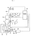
- a casting machine such as a die-casting machine includes a stationary metal mold 11 and a movable metal mold 12 movable relative to the stationary metal mold 11.
- a mold cavity 13 is defined between the molds 11 and 12.
- a shot sleeve 15 having a pouring port 16 is provided in communication with the mold cavity 13, and a plunger tip 17 is slidably disposed in the shot sleeve 15.
- the plunger tip 17 is driven by an injection cylinder 19 through a cylinder rod 19a to which a striker 18 is provided.
- the striker 18 is provided abuttable on a vacuum start limit switch 20 and a high speed limit switch 21 during moving stroke of the cylinder rod 19a.
- These limit switches 20, 21 are connected to a control circuit 10.
- the gas discharging apparatus is adapted for discharging gas existing in the metal molds or generated at the casting out of the metal molds by the application of negative pressure.
- the gas discharging apparatus includes a gas vent valve 5 connected to a gas vent passage formed in the stationary metal mold 11 and communicated with the mold cavity 13, a first electromagnetic valve 8 connected to the gas vent valve 5, a vacuum tank 7 connected to the first electromagnetic valve 8, and a vacuum pump 6 connected to the vacuum tank 7. These are connected to each other by gas exhaust line 4 (4a, 4e).
- the first electromagnetic valve 8 is connected to the control circuit 10 which is adapted to generate change-over signals for moving the first electromagnetic valve 8 into a first change-over position 8X where the vacuum tank 7 is communicated with the gas vent valve 5, and for moving the first electromagnetic valve 8 into a second change-over position where the gas vent valve is shut off from the vacuum tank 7.
- a metal molds venting device generally includes second and third electromagnetic valves 3, 9, and a suction unit (blower) 1.
- the second electromagnetic valve 3 is connected to the gas vent valve 5 by way of the gas exhaust line 4 (4a, 4b), and the suction unit 1 is connected to the second electromagnetic valve 3 by way of the gas exhaust line 4 (4c).
- the second electromagnetic valve 3 is connected to the control circuit 10 which generates signals for moving the second electromagnetic valve 3 into a first change-over position 3X where the gas vent valve 5 is communicated with the suction unit 1, and into a second change-over position 3Y where communication therebetween is shut off.
- the third electromagnetic valve 9 is connected to the gas vent valve 5 through the gas discharge line 4(4a, 4d) at a position upstream of the first and second electromagnetic valves 8, 3.
- the control circuit 10 transmits signals to the third electromagnetic valve 9 for moving the same to its first change-over position 9X where communication between the gas exhaust line 4 and an atmosphere is blocked and to its second change-over position 9Y where the gas exhaust line 4 is communicate
- the metal molds Prior to the casting, the metal molds are open which is the last phase of the last shot cycle, and the gas vent valve 5 is close. Further, the first electromagnetic valve 8 is positioned to its second change-over position 8Y where the gas vent valve 5 is disconnected from the vacuum tank 7. Furthermore, the second electromagnetic valve 3 is positioned at its second change-over position 3Y where the suction unit 1 and the gas vent valve 5 are disconnected from each other. Moreover, the third electromagnetic valve 9 is positioned at its first change-over position 9X where the gas exhaust line is disconnected from the atmosphere.
- Step S1 air-blow signal is outputted, and in Step S2 valve opening signal is outputted to the gas vent valve 5, and in Step S3 the metal molds are closed, and in Step S4 the second electromagnetic valve 3 is moved to its first change-over position 3X.
- the first electromagnetic valve 8 is positioned in its second change-over position 8Y and the third electromagnetic valve 9 is positioned in its first change-over position 9X.
- Step S5 molten metal is poured through the pouring port 16, and in Step S6, injection is started upon transmission of a drive signal to the injection cylinder 19.
- the striker 18 moves forwardly,and in Step S7, the plunger tip 17 closes the pouring port 16 and abuts the vacuum start limit switch 20 to turn ON the switch 20.
- Step S8 the second electromagnetic valve 3 is moved to its second change-over position 3Y.
- Step S9 the change-over signal is transmitted to move the first electromagnetic valve 8 into its first change-over position 8X.
- decompression is started, so that the contaminated gas in the mold cavity 13 and the gas vent passage 14 is suckedly discharged and is introduced into the vacuum tank 7 through the gas vent valve 5 and the first electromagnetic valve 8.
- Steps S7 through S9 after the pouring port 16 is closed by the plunger tip 17, the striker 18 abuts the vacuum start switch 20 to render the switch 20 ON, so that the second electromagnetic valve 3 is moved to its second change-over position 3Y for stopping suction by the suction unit 1. Immediately thereafter, the first electromagnetic valve 8 is moved to its first change-over position 8X to start decompression.
- Step S10 the gas vent valve 5 is closed at a predetermined timing to prevent the molten metal from leaking there-through. As a result, the molten metal filling is completed.
- Step S11 the first electromagnetic valve 8 is changed-over to its second change-over position 8Y.
- Step S12 the third electromagnetic valve 9 is changed-over to its second change-over position 9Y by the control circuit 10 for introducing atmospheric pressure into the gas exhaust line 4.
- Step S13 the third electromagnetic valve 9 is changed-over to its first change-over position 9X.
- Step S14 the metal molds are open to take out the casted product, and cooling water is sprayed onto the metal molds, and the release agent is coated thereover.
- Step S15 judgment is made as to whether or not a casting stop button is rendered ON. If not (S15: No), the routine returns back to the Step S1 to repeat the same processing. If turned ON, the processing is finished.
- venting stop timing for the metal molds (valve closing timing of the second electromagnetic valve 3 in the Step S8) is responsive to the ON operation of the vacuum start limit switch in the Step S7.
- this venting stop timing can be responsive to the injection start signal in the Step S6.
- the second electromagnetic valve 3 must be positioned to its second change-over position 3Y by the time the decompression starts with respect to the mold cavity 13.
Landscapes
- Engineering & Computer Science (AREA)
- Mechanical Engineering (AREA)
- Moulds For Moulding Plastics Or The Like (AREA)
- Injection Moulding Of Plastics Or The Like (AREA)
Claims (7)
- Ein Verfahren zum Entlüften von Gas aus Metallformen, umfassend den Schrittdes Öffnens eines Gasabzugsventils, das in einem Gasabzugsdurchlaß in Verbindung mit einem in der Metallform ausgebildeten Formhohlraum vorgesehen ist; unddes Entspannens des Formhohlraums durch ein erstes Saugmittel durch das Gasabzugsventil zum Entfernen des Gases in dem Formhohlraum, um ein Gaseindringen in ein in den Formhohlraum eingespritztes geschmolzenes Metall zu vermeiden; und umfassend die Schritte:Entlüften des Formhohlraums durch ein zweites Saugmittel unabhängig von dem ersten Saugmittel durch das Gasabzugsventil nach Schließen der Metallformen und bis zum Beginn des Entspannungsschritts, um kontaminiertes Gas aus den Metallformen zu entfernen und das kontaminierte Gas durch Frischluft in einer Phase vor dem Einspritzen des geschmolzenen Metalls zu ersetzen.
- Das Verfahren nach Anspruch 1, bei dem die Frischluft durch den Sog der Metallformen durch das zweite Saugmittel in die Metallformen durch einen Strömungseinlaß einer Druckkammer eingeführt wird.
- Das Verfahren nach Anspruch 2, bei dem der Entlüftungsschritt durchgeführt wird, bis ein Vakuumbeginn-Begrenzungsschalter auf EIN geschaltet wird.
- Das Verfahren nach Anspruch 3, bei dem der Entspannungsschritt begonnen wird, wenn der Vakuumbeginn-Begrenzungsschalter auf EIN geschaltet wird.
- Eine Vorrichtung zum Entfernen von Gas aus Metallformen mit einem Formhohlraum (13), einem Gasabzugsdurchlaß in Verbindung mit dem Formhohlraum und einem Gasabzugsventil (5), das in dem Gasabzugsdurchlaß angeordnet ist, wobei die Vorrichtung ein erstes Saugmittel (6, 7, 8) zum Ansaugen von Gas in den Formhohlraum durch das Gasabzugsventil einschließt, und weiterhin umfassend:ein zweites Saugmittel (1, 3), das unabhängig von dem ersten Saugmittel vorgesehen ist, wobei das zweite Saugmittel mit dem Gasabzugsventil verbunden ist, um den Formhohlraum durch Ansaugen eines Gases in die Metallformen zwangszubelüften; undSteuermittel (10), die mit dem ersten und zweiten Saugmittel verbunden sind, um das erste Saugmittel sofort nach dem erzwungenen Belüftungsvorgang des zweiten Saugmittels zu betätigen.
- Die Vorrichtung nach Anspruch 5, bei der das erste Saugmittel eine Vakuumpumpe (6), einen Vakuumbehälter (7) und ein erstes Umschaltventil (8) umfaßt, das zwischen dem Vakuumbehälter und dem Gasabzugsventll geschaltet ist, wobei das erste Umschaltventil mit den Steuermitteln (10) verbunden ist, um selektiv negativen Druck an die Metallformen anzulegen.
- Die Vorrichtung nach Anspruch 5, bei der das zweite Saugmittel ein Gebläse (1) und ein zweites Umschaltventil (3) umfaßt, das zwischen dem Gebläse und dem Gasabzugsventil geschaltet ist, wobei das zweite Umschaltventil auch mit den Steuermitteln zum selektiven Anlegen negativen Drucks an die Metallformen geschaltet ist.
Applications Claiming Priority (2)
| Application Number | Priority Date | Filing Date | Title |
|---|---|---|---|
| JP338077/92 | 1992-11-25 | ||
| JP4338077A JP2736491B2 (ja) | 1992-11-25 | 1992-11-25 | 金型内ガス排出方法及びその装置 |
Publications (2)
| Publication Number | Publication Date |
|---|---|
| EP0599508A1 EP0599508A1 (de) | 1994-06-01 |
| EP0599508B1 true EP0599508B1 (de) | 1997-10-01 |
Family
ID=18314692
Family Applications (1)
| Application Number | Title | Priority Date | Filing Date |
|---|---|---|---|
| EP93308848A Expired - Lifetime EP0599508B1 (de) | 1992-11-25 | 1993-11-05 | Verfahren und Vorrichtung zum Entfernen von Gas aus einer Kokille |
Country Status (4)
| Country | Link |
|---|---|
| US (1) | US5460218A (de) |
| EP (1) | EP0599508B1 (de) |
| JP (1) | JP2736491B2 (de) |
| DE (1) | DE69314285T2 (de) |
Families Citing this family (16)
| Publication number | Priority date | Publication date | Assignee | Title |
|---|---|---|---|---|
| US5685360A (en) * | 1996-03-14 | 1997-11-11 | Peacock Limited L.C. | Apparatus for the casting and autogenous welding of small metal loads in an inert atmosphere |
| DE19628870A1 (de) * | 1996-07-17 | 1998-01-22 | Alusuisse Bayrisches Druckgus | Vorrichtung und Verfahren zur Herstellung von Druckgußteilen |
| DE19841229A1 (de) * | 1998-09-09 | 2000-03-16 | Alusuisse Bayrisches Druckgus | Druckgießmaschine für den Leichtmetallguß in einer evakuierten Form |
| DE10144945B4 (de) * | 2001-09-12 | 2005-05-04 | Alcan Bdw Gmbh & Co. Kg | Verfahren zum Steuern eines Vakuumventils einer Vakuumdruckgießvorrichtung sowie Vakuumdruckgießvorrichtung |
| US20030206984A1 (en) * | 2002-05-01 | 2003-11-06 | Bellasalma Gerard Jay | Air introduction valve for a mold assembly |
| US7184298B2 (en) | 2003-09-24 | 2007-02-27 | Innovative Silicon S.A. | Low power programming technique for a floating body memory transistor, memory cell, and memory array |
| JP2006334649A (ja) * | 2005-06-03 | 2006-12-14 | Toyota Motor Corp | ダイカスト装置およびダイカスト方法 |
| JP5726443B2 (ja) * | 2010-06-10 | 2015-06-03 | 株式会社ダイエンジニアリング | 高品質ダイカスト鋳造方法 |
| KR101423130B1 (ko) * | 2012-06-22 | 2014-07-31 | 주식회사 엠피에이테크놀로지 | 진공 사출성형장치 |
| JP2014034057A (ja) * | 2012-08-10 | 2014-02-24 | Honda Motor Co Ltd | 減圧鋳造装置及び減圧鋳造方法 |
| DE102012220513B4 (de) | 2012-11-12 | 2023-02-16 | Bayerische Motoren Werke Aktiengesellschaft | Verfahren und Vorrichtung zur Herstellung eines Druckgussteils |
| CN105170939B (zh) * | 2015-08-14 | 2017-06-16 | 厦门理工学院 | 真空机 |
| CN108889921B (zh) * | 2018-07-05 | 2020-11-17 | 宁波北仑益鸣企业管理服务有限公司 | 模具抽真空装置及相应的抽真空作业的工艺 |
| EP4219043A1 (de) * | 2022-01-26 | 2023-08-02 | Fundación Azterlan | Vakuumdruckverfahren und vorrichtung zum hochdruckgiessen |
| CN115070007B (zh) * | 2022-07-29 | 2025-07-25 | 东风本田发动机有限公司 | 真空减压排气组件及真空减压铸造装置 |
| CN118682102B (zh) * | 2024-08-23 | 2024-11-12 | 宁波赛维达技术股份有限公司 | 一种新能源汽车滤清器用一体化压铸模具 |
Family Cites Families (8)
| Publication number | Priority date | Publication date | Assignee | Title |
|---|---|---|---|---|
| JPS5915740B2 (ja) * | 1981-11-13 | 1984-04-11 | 旭東ダイカスト株式会社 | 真空ダイカスト鋳造法およびその装置 |
| JPS603959A (ja) * | 1983-06-20 | 1985-01-10 | Ube Ind Ltd | 鋳造方法 |
| JPS60127063A (ja) * | 1984-10-23 | 1985-07-06 | Ube Ind Ltd | 金型用ガス抜き装置を用いた射出成形法 |
| JPS63132760A (ja) * | 1986-11-25 | 1988-06-04 | Kobe Steel Ltd | 高品質金型鋳物のガス抜き方法 |
| JPH0787966B2 (ja) * | 1987-02-24 | 1995-09-27 | 本田技研工業株式会社 | 複合鋳型 |
| JPH0714194B2 (ja) * | 1987-06-24 | 1995-02-15 | コニカ株式会社 | 画像形成装置 |
| JPH04123860A (ja) * | 1990-09-14 | 1992-04-23 | Ryobi Ltd | 射出成形機におけるガス抜き装置制御方法と制御装置 |
| DE4123463A1 (de) * | 1991-07-16 | 1993-01-21 | Audi Ag | Verfahren zur herstellung von gussstuecken mittels einer druckgiessmaschine |
-
1992
- 1992-11-25 JP JP4338077A patent/JP2736491B2/ja not_active Expired - Fee Related
-
1993
- 1993-11-05 DE DE69314285T patent/DE69314285T2/de not_active Expired - Fee Related
- 1993-11-05 EP EP93308848A patent/EP0599508B1/de not_active Expired - Lifetime
- 1993-11-22 US US08/155,330 patent/US5460218A/en not_active Expired - Fee Related
Also Published As
| Publication number | Publication date |
|---|---|
| EP0599508A1 (de) | 1994-06-01 |
| JP2736491B2 (ja) | 1998-04-02 |
| US5460218A (en) | 1995-10-24 |
| DE69314285D1 (de) | 1997-11-06 |
| DE69314285T2 (de) | 1998-04-30 |
| JPH06179063A (ja) | 1994-06-28 |
Similar Documents
| Publication | Publication Date | Title |
|---|---|---|
| EP0599508B1 (de) | Verfahren und Vorrichtung zum Entfernen von Gas aus einer Kokille | |
| US4949775A (en) | Die casting arrangements | |
| JP2004249334A (ja) | 酸素シールドを用いた高真空ダイカスト法 | |
| JPS5772766A (en) | Molding method by vacuum die casting | |
| US4562875A (en) | Die-casting method and apparatus | |
| JP2003170479A (ja) | 金型のガス抜き方法と装置、及び射出成形機 | |
| EP0592184B1 (de) | Verfahren und Vorrichtung zur Erfassung von Fehlern bei einer Entlüftungsvorrichtung einer Giessmaschine | |
| JP2570541B2 (ja) | 鋳造装置 | |
| JPH06122057A (ja) | 鋳造装置における離型剤塗布方法および装置 | |
| US5072772A (en) | Method for moulding objects and installations for carrying out the process | |
| JPS642469B2 (de) | ||
| JPS62104659A (ja) | 圧力鋳造のガス抜き装置 | |
| JPH04123860A (ja) | 射出成形機におけるガス抜き装置制御方法と制御装置 | |
| JP3655992B2 (ja) | 真空ダイカスト鋳造装置および鋳造方法 | |
| JP2903977B2 (ja) | ガス硬化鋳型の造型装置 | |
| JPS6129821B2 (de) | ||
| JPH034299B2 (de) | ||
| JP2840107B2 (ja) | 低圧鋳造方法および装置 | |
| JP2002361687A (ja) | 射出成形型の付着物除去方法 | |
| JPS6151968B2 (de) | ||
| JP2001047483A (ja) | 射出成形機 | |
| JPS5823559A (ja) | 真空無孔性ダイカスト法 | |
| JPS5639164A (en) | Method and device for removing casting sprue | |
| JPS6192768A (ja) | 水分除去装置を備えた金型装置 | |
| JPS5570467A (en) | Vacuum suction casting method |
Legal Events
| Date | Code | Title | Description |
|---|---|---|---|
| PUAI | Public reference made under article 153(3) epc to a published international application that has entered the european phase |
Free format text: ORIGINAL CODE: 0009012 |
|
| AK | Designated contracting states |
Kind code of ref document: A1 Designated state(s): DE FR GB |
|
| 17P | Request for examination filed |
Effective date: 19940929 |
|
| GRAG | Despatch of communication of intention to grant |
Free format text: ORIGINAL CODE: EPIDOS AGRA |
|
| GRAH | Despatch of communication of intention to grant a patent |
Free format text: ORIGINAL CODE: EPIDOS IGRA |
|
| 17Q | First examination report despatched |
Effective date: 19970129 |
|
| GRAH | Despatch of communication of intention to grant a patent |
Free format text: ORIGINAL CODE: EPIDOS IGRA |
|
| GRAA | (expected) grant |
Free format text: ORIGINAL CODE: 0009210 |
|
| AK | Designated contracting states |
Kind code of ref document: B1 Designated state(s): DE FR GB |
|
| PGFP | Annual fee paid to national office [announced via postgrant information from national office to epo] |
Ref country code: GB Payment date: 19971027 Year of fee payment: 5 |
|
| REF | Corresponds to: |
Ref document number: 69314285 Country of ref document: DE Date of ref document: 19971106 |
|
| ET | Fr: translation filed | ||
| PGFP | Annual fee paid to national office [announced via postgrant information from national office to epo] |
Ref country code: FR Payment date: 19971112 Year of fee payment: 5 |
|
| PGFP | Annual fee paid to national office [announced via postgrant information from national office to epo] |
Ref country code: DE Payment date: 19971114 Year of fee payment: 5 |
|
| PLBE | No opposition filed within time limit |
Free format text: ORIGINAL CODE: 0009261 |
|
| 26N | No opposition filed | ||
| PG25 | Lapsed in a contracting state [announced via postgrant information from national office to epo] |
Ref country code: GB Free format text: LAPSE BECAUSE OF NON-PAYMENT OF DUE FEES Effective date: 19981105 |
|
| GBPC | Gb: european patent ceased through non-payment of renewal fee |
Effective date: 19981105 |
|
| PG25 | Lapsed in a contracting state [announced via postgrant information from national office to epo] |
Ref country code: FR Free format text: LAPSE BECAUSE OF NON-PAYMENT OF DUE FEES Effective date: 19990730 |
|
| REG | Reference to a national code |
Ref country code: FR Ref legal event code: ST |
|
| PG25 | Lapsed in a contracting state [announced via postgrant information from national office to epo] |
Ref country code: DE Free format text: LAPSE BECAUSE OF NON-PAYMENT OF DUE FEES Effective date: 19990901 |