EP0599568A2 - Dispositif de mesure de temps - Google Patents
Dispositif de mesure de temps Download PDFInfo
- Publication number
- EP0599568A2 EP0599568A2 EP93309259A EP93309259A EP0599568A2 EP 0599568 A2 EP0599568 A2 EP 0599568A2 EP 93309259 A EP93309259 A EP 93309259A EP 93309259 A EP93309259 A EP 93309259A EP 0599568 A2 EP0599568 A2 EP 0599568A2
- Authority
- EP
- European Patent Office
- Prior art keywords
- lap time
- time
- lap
- standard
- measuring
- Prior art date
- Legal status (The legal status is an assumption and is not a legal conclusion. Google has not performed a legal analysis and makes no representation as to the accuracy of the status listed.)
- Granted
Links
Images





Classifications
-
- G—PHYSICS
- G04—HOROLOGY
- G04F—TIME-INTERVAL MEASURING
- G04F10/00—Apparatus for measuring unknown time intervals by electric means
- G04F10/04—Apparatus for measuring unknown time intervals by electric means by counting pulses or half-cycles of an AC
Definitions
- the present invention is related to a time measurement apparatus such as a stopwatch, a chronograph watch etc., that is capable of measuring a LAP time.
- a LAP time means an elapse of time between the first LAP operation timing and the next LAP operation timing after starting measurement.
- LAP time is measured by a plurality of LAP timing apparatus.
- a split time means the total addition of specific LAP times that have elapsed after standing.
- a "combination watch” with chronographic function which has a function that can foresee a timing of the next LAP operation.
- This type of a watch in chronographic mode displays, at the digital display portion of the choreographic time (the total addition of time from the start) or the LAP time (a period of time), and at the analogue display portion, a simulational display by a rotating hand, of which one revolution is equal to 100% of the latest LAP time or the target LAP time.
- a watcher may wish to avoid the delay of the LAP operation because the car passes through too fast in front of the watcher and then that delays the recognition of the car. This kind of delay will be avoided by showing that the hand of the watch circulates in proportion to the percentage of the elapsed time out of 100% of the latest LAP time or the car LAP time which is equal to one car circuit.
- a stop watch is also known with a function that the LAP time difference is calculated and displayed between a standard LAP time and a LAP time which is measured. By this function, a watcher can identify how fast or how slow the LAP time is, compared with a standard LAP time.
- An object of this invention is to provide such a time measurement apparatus which forecasts the next time of the LAP operation and compare it with a standard LAP time, without an operator having to watch the display of the apparatus.
- the first constitution in such a time measurement apparatus as a stopwatch and chronograph that is capable of LAP time measurement, comprises a standard LAP time memory means memorising the latest LAP time, or such a standard LAP time as is to be set with discretion by a switch, LAP time watching means for watching whether or not LAP time that is just now measured coincides with a period of time subtracting a determined time from a standard LAP time memorised in the LAP time memory means, output signal memory means that generates a output signal for driving informing means by receiving the output of LAP time watching means, a driving circuit, and informing means.
- a standard LAP time memory means memorising the latest LAP time, or such a standard LAP time as is to be set with discretion by a switch
- LAP time watching means for watching whether or not LAP time that is just now measured coincides with a period of time subtracting a determined time from a standard LAP time memorised in the LAP time memory means
- output signal memory means that generates a output signal for driving
- the second constitution in such a time measurement apparatus as a stopwatch and a chronograph that is capable of measurement of LAP time, comprises standard LAP time memory means, LAP time difference calculating means that calculates time difference between a LAP time and a standard LAP time through operation by a switch and outputs its LAP time difference signal, output signal memory means that generates an output signal that drives informing means in relation to the LAP time difference signal, a driving circuit, and informing means.
- the latest LAP time to be measured by LAP operation, or standard LAP time etc. of such a target LAP time etc. as is set by a switch are memorised in standard LAP time memory means, and when a new LAP time is initiated to be measured by LAP operation, it is continuously watched by LAP time watching means whether or not the LAP time now in process of measurement coincides with the period of a time subtracting a determined time from a LAP time memorised in standard LAP time memory means.
- an output signal is generated by LAP time watching means to output signal memory means and an output signal for driving informing means is generated. Since through this operation a signal is conveyed when a LAP time now in process of measurement comes just into the time subtracting a determined time from a standard LAP time, a next LAP operation timing can be foreseen.
- a standard LAP time of the latest LAP time measured by LAP operation, the target LAP time set by switch, etc. is memorised in standard LAP time memory means, and in LAP time difference calculating means calculates the LAP time difference between the LAP time measured by LAP time calculating means and the standard LAP time is calculated and a LAP time difference signal is output to output signal memory means in accordance with the LAP time difference above. From output signal memory means, an output signal in accordance with the LAP time difference is output to the informing means.
- the information corresponding to the difference between the LAP time immediately after the measurement and standard LAP time is made, that is to say, the information in accordance with the LAP time difference above is made. Accordingly, the information of the LAP time difference can be recognised.
- FIG. 1 shows the Function block diagram in relation to the first embodiment of a time measurement apparatus according to the present invention.
- LAP time measuring circuit 1 LAP times are measured in terms of an hour, minute, second, and 1/10 second.
- a standard LAP time memory circuit 2 memorises a LAP time to be a standard, such as the latest LAP time measured by the LAP time measuring circuit 1 or a target LAP time set by a switch 9.
- a LAP time watching circuit 3 watches if the LAP time now in the process of being measured in the LAP time measuring circuit 1 coincides with the timing which is equal to the value which is equal to subtracting a predetermined time from the standard LAP time memorised in the standard LAP time memory circuit 2. When such coincidence is identified a LAP time coincidence signal is output to an output signal memory circuit 4.
- Output signal memory circuit 4 drives informing element 6 by way of a driving circuit 5 on receiving the LAP time coincidence signal from the LAP time watching circuit 3.
- a datum of 1 minute 50 seconds is memorised in the standard LAP time memory circuit 2.
- the standard LAP time memory circuit 2 memorises a datum of 1 minute 40 seconds. This is a calculation which is done beforehand of a value subtracting the predetermined time of 10 seconds from the target LAP time of 1 minute 50 seconds.
- the LAP time measuring circuit 1 continuously watches if the LAP time now in the process of being measured coincides with the above-mentioned 1 minute 40 seconds.
- the timing of such a coincidence above means the output of the LAP time coincidence signal to the signal memory 4, and drives the informing element 6 by way of the driving circuit 5. That is to say, when the LAP time now in the process of being measured comes to, and just passes, through 1 minute 40 seconds, which is equal to the target LAP time of 10 seconds before 1 minute 50 seconds, the information conveyance is made and accordingly it is recognised that the standard LAP time is coming closer.
- Informing element 6 may make a sound from say a speaker or may be with a motor which generates vibrations.
- Display element 7 displays such information as the LAP time, the standard LAP time, etc.
- the display element may be a digital display, like an LED or LCD, or may be an analogue display, like hands etc.
- a display control circuit 8 controls the contents output to the display element 7 and also controls how it is displayed.
- the switch 9 enables operation to be made, such as by the LAP time measuring circuit 1 in what it is measuring (start, stop, LAP, reset etc.), and conversion and reconversion of displayed information, and of setting standard LAP time etc.
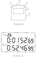
- Figure 3 shows an external appearance of the first embodiment and the second embodiment of a time measurement apparatus in the present invention.
- a display panel 14 is made up of LCD (liquid crystal display) which operates with lower energy consumption.
- Figure 4 shows an external appearance of the first embodiment and the second embodiment of a time measurement apparatus in the present invention. At the upper portion the LAP number is displayed, at the middle the LAP time, and at the lower split time.
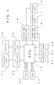
- FIG. 5 shows a systems block diagram of the first embodiment and the second embodiment of a time measurement apparatus in the present invention.
- An output signal from an oscillating circuit 16 is input into a dividing circuit 17, which outputs a plurality of timing signals into an interrupt signal generating circuit 18.
- the interrupt signal generating circuit 18 generates an interrupt signal for a CPU (central processing unit) 19.
- CPU 19 receives system clock signals from systems clock signal generating circuit 29 and drives a program memorised in a ROM (read only memory) 20 due to an interrupt signal from the interrupt signal generating circuit 18.
- the LAP time measurement or LAP time watching etc. are processed.
- CPU 19 drives a liquid crystal display driving circuit 23 and a buzzer driving circuit 25, and through these operations, a liquid crystal display 22 and a buzzer 24 are driven respectively.
- a RAM (random access memory) 21 there are memorised, such data as LAP time, standard LAP time, etc. and the renewal or storing of those, of many kinds of data or information which are also processed through such a program operation as above.
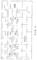
- Figures 6 and 7 shows a RAM MAP of the first embodiment of a time measurement apparatus in the present invention, which shows how many kinds of data are stored in the RAM.
- a LAP time data 34 consists of 1/10 second datum 30, second datum 31, minute datum 32, hour datum 33, those of which data are renewed respectively along with the elapse of LAP time in every a 1/10 second, second, minute, and an hour.
- a standard LAP time data 39 also consists, the same as the LAP time data above, of a 1/10 second datum 35, second datum 36, minute datum 37, and hour datum 38.
- Figure 8 shows a flow chart of procedures of the LAP switch operation in the first embodiment apparatus.
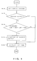
- Figure 9 shows a flow chart of procedures of the LAP time watching operation in the first embodiment. The operations in the first embodiment will be explained in the following according to the flow charts.
- the LAP time data area 34 is cleared for the purpose of restarting the LAP time measurement (step 50).
- the datum revision of the standard LAP time data 39 is made.
- the datum revision is for easy watching of the LAP time. That is, in reality, the deduction of a predetermined time from a standard LAP time is made beforehand.
- the datum of subtracting say 10 seconds, from the standard LAP time is stored as the standard LAP time datum (step 51).
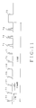
- Figure 11 shows a buzzer driving waveform in the first embodiment of the time measurement apparatus in the present invention.
- an output to the buzzer is initiated.
- a buzzer driving wave as shown in Figure 11 is output from the buzzer driving circuit 25 into the buzzer 24.
- the buzzer output level is "High" in Figure 11
- a rectangular wave of 4 kHz is assumed to be the output.
- Up to 6 seconds from the buzzer output initiation about a 63 milli-second shot sound output signal is generated every 1 second (driving waveforms 65-71).
- two shot sound output signals with intervals of 1 second are generated every 1 second (driving waveforms 72-74).
- a continuous sound of 1 second is generated at the 10th second (driving waveform 75).
- the standard LAP time means the LAP time of which the revision is made in step 51.
- the standard LAP time with which LAP time in the LAP time watching procedure is compared is the time which is 10 seconds before LAP time (the previous LAP time) at the timing of the input by the LAP switch, the real behaviour is as follows.
- FIG. 2 shows a functional block diagram of the second embodiment of a time measurement apparatus in the present invention.
- the elements, other than a LAP time difference calculating circuit 10, are the same as in the first embodiment.
- the LAP time measuring circuit 1 an input by the switch 9 is made while the LAP time which is now in the process of being measured, the LAP time difference is calculated between the standard LAP time memorised in the standard LAP time memory circuit 2 and the LAP time measured by the LAP time measuring circuit 1.
- the LAP time difference signal is output into output signal memory circuit 4, which then drives informing element 6 by way of the driving circuit 5 in accordance with the LAP time difference signal from the LAP time difference calculating circuit 10.
- a target LAP time is equal to 1 minute 50 seconds
- a datum of 1 minute 50 seconds is memorised into the standard LAP time memory circuit 2.
- a LAP time difference (it is 3 seconds in this particular case) between the LAP time and the standard LAP time is calculated in the LAP time difference calculating circuit.
- the LAP time difference signal is output to the output signal memory circuit 4, and the informing element 6 is driven in accordance with the LAP time difference. That is, through the LAP measuring operation, the LAP time difference between the LAP time and the standard LAP time can be recognised by the informing function.
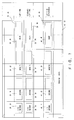
- Figure 7 shows a RAM MAP of the second embodiment of a time measurement apparatus in the present invention.
- the difference from the first embodiment is that an area 45 for memorising the LAP time difference is added.
- the area 45 consists of 1/10 second datum 41, second datum 42, minute datum 43, and hour datum 44.
- the data of the LAP time difference are memorised into the area 45.
- FIG 10 shows a flow chart of the procedure of the LAP time switch operation in the second embodiment of a time measurement apparatus in the present invention. Operation of the second embodiment will be explained in the following with reference to the flow chart.
- the LAP time datum is transferred to a standard LAP time data area (step 59), and is substituted for the standard LAP time at the next LAP operation.
- the LAP time datum is transferred to the LAP time difference data area (step 60). Using the LAP time difference data area, a standard LAP time datum is deducted from the LAP time difference datum.
- the standard LAP time is deducted in reality from the LAP time (step 61). Then, the LAP time difference and the LAP time are displayed (step 62). The LAP time is cleared (step 63) and the output for a buzzer is initiated (step 64).
- Figure 12 shows a buzzer driven waveform in the second embodiment of a time measurement apparatus in the present invention.
- the previous LAP time is used for the standard LAP time.
- the standard LAP time may not necessarily be the previous LAP time.
- a user's predetermined target LAP time may be also used as a standard LAP time for its comparison base.
- information conveyance is done when the LAP time which is now in the process of being measured comes to and/or falls into a certain length of time just before a standard LAP time.
- the informing function is done in accordance with the LAP time difference between a LAP time just now measured and a standard LAP time. Therefore, users can avoid troublesome frequent confirmation, by looking at the display means, in every LAP of every turn of a circuit race, since they can confirm the next LAP operation timing or LAP time difference by way of the informing function as in the present invention, while they are watching the races.
Landscapes
- Engineering & Computer Science (AREA)
- Power Engineering (AREA)
- Physics & Mathematics (AREA)
- General Physics & Mathematics (AREA)
- Measurement Of Unknown Time Intervals (AREA)
Applications Claiming Priority (2)
| Application Number | Priority Date | Filing Date | Title |
|---|---|---|---|
| JP4311706A JPH06160549A (ja) | 1992-11-20 | 1992-11-20 | 計時装置 |
| JP311706/92 | 1992-11-20 |
Publications (3)
| Publication Number | Publication Date |
|---|---|
| EP0599568A2 true EP0599568A2 (fr) | 1994-06-01 |
| EP0599568A3 EP0599568A3 (fr) | 1996-03-20 |
| EP0599568B1 EP0599568B1 (fr) | 1998-07-29 |
Family
ID=18020491
Family Applications (1)
| Application Number | Title | Priority Date | Filing Date |
|---|---|---|---|
| EP93309259A Expired - Lifetime EP0599568B1 (fr) | 1992-11-20 | 1993-11-19 | Dispositif de mesure de temps |
Country Status (4)
| Country | Link |
|---|---|
| US (1) | US5404341A (fr) |
| EP (1) | EP0599568B1 (fr) |
| JP (1) | JPH06160549A (fr) |
| DE (1) | DE69320004T2 (fr) |
Cited By (1)
| Publication number | Priority date | Publication date | Assignee | Title |
|---|---|---|---|---|
| JP2012150055A (ja) * | 2011-01-20 | 2012-08-09 | Seiko Instruments Inc | 電子機器、時計装置、プログラム |
Families Citing this family (9)
| Publication number | Priority date | Publication date | Assignee | Title |
|---|---|---|---|---|
| US5642334A (en) * | 1995-12-18 | 1997-06-24 | Liberman; Michael | Pacing device for taking an examination |
| JPH11109067A (ja) * | 1997-10-01 | 1999-04-23 | Citizen Watch Co Ltd | 小型電子機器 |
| US6909671B2 (en) * | 2002-07-18 | 2005-06-21 | Charles G. Setler | Time computing device and predictive method therefor |
| US9052717B1 (en) | 2004-02-11 | 2015-06-09 | Enovation Controls, Llc | Watercraft speed control device |
| US20080243321A1 (en) | 2005-02-11 | 2008-10-02 | Econtrols, Inc. | Event sensor |
| US7571049B2 (en) * | 2004-04-07 | 2009-08-04 | Edward Andrew Kelly | Timing device, system and method for estimated time of arrival (ETA) |
| US9207675B1 (en) | 2005-02-11 | 2015-12-08 | Enovation Controls, Llc | Event sensor |
| CN1991640B (zh) * | 2005-12-27 | 2011-03-02 | 比亚迪股份有限公司 | 瞬时通断时间测量仪 |
| WO2014008388A1 (fr) | 2012-07-03 | 2014-01-09 | Jordan Liss | Dispositif déterminant un rythme et doté d'un mode test, et procédés connexes |
Family Cites Families (10)
| Publication number | Priority date | Publication date | Assignee | Title |
|---|---|---|---|---|
| JPS5338366A (en) * | 1976-09-20 | 1978-04-08 | Seiko Instr & Electronics Ltd | Electronic watch |
| GB2070809B (en) * | 1980-02-09 | 1983-10-26 | Middleton R | Timing device |
| JPS5940290A (ja) * | 1982-08-31 | 1984-03-05 | Seiko Epson Corp | アナログ多機能時計 |
| US4637732A (en) * | 1983-12-05 | 1987-01-20 | Charles Jones | Hand held athletic officiating timers |
| US4831605A (en) * | 1986-03-25 | 1989-05-16 | Casio Computer Co., Ltd. | Electronic time measuring apparatus including past record display means |
| JPH01100495A (ja) * | 1987-10-13 | 1989-04-18 | Seiko Epson Corp | ストップウォッチ |
| JPH0348794A (ja) * | 1989-07-18 | 1991-03-01 | Seiko Instr Inc | タイマー機能付電子時計 |
| US5088072A (en) * | 1990-05-31 | 1992-02-11 | Bernard Fitzmorris | Sport counting and timing device |
| US5050141A (en) * | 1990-07-30 | 1991-09-17 | Timex Corporation | Program to synchronize pace in a multimode alarm timepiece |
| US5130955A (en) * | 1990-12-11 | 1992-07-14 | Dean Luerker | Athletic timer correction system |
-
1992
- 1992-11-20 JP JP4311706A patent/JPH06160549A/ja active Pending
-
1993
- 1993-10-20 US US08/140,216 patent/US5404341A/en not_active Expired - Lifetime
- 1993-11-19 DE DE69320004T patent/DE69320004T2/de not_active Expired - Fee Related
- 1993-11-19 EP EP93309259A patent/EP0599568B1/fr not_active Expired - Lifetime
Cited By (1)
| Publication number | Priority date | Publication date | Assignee | Title |
|---|---|---|---|---|
| JP2012150055A (ja) * | 2011-01-20 | 2012-08-09 | Seiko Instruments Inc | 電子機器、時計装置、プログラム |
Also Published As
| Publication number | Publication date |
|---|---|
| US5404341A (en) | 1995-04-04 |
| DE69320004T2 (de) | 1998-12-03 |
| EP0599568B1 (fr) | 1998-07-29 |
| JPH06160549A (ja) | 1994-06-07 |
| EP0599568A3 (fr) | 1996-03-20 |
| DE69320004D1 (de) | 1998-09-03 |
Similar Documents
| Publication | Publication Date | Title |
|---|---|---|
| JP3334279B2 (ja) | ピッチ表示装置 | |
| EP0599568A2 (fr) | Dispositif de mesure de temps | |
| US8284634B2 (en) | User interface features for a watch | |
| JPH02119307A (ja) | 選局装置 | |
| US4255803A (en) | Electronic timepiece equipped with alarm function | |
| US5448533A (en) | Method and apparatus for accurate time maintenance and display | |
| US4104861A (en) | Electronic stop watch | |
| US5130957A (en) | Electronic timepiece with timer | |
| JP2526938B2 (ja) | プログラマブル・タイムスイツチ | |
| CA1072749A (fr) | Chronometre electronique a avertisseur periodique ou simple | |
| US6128252A (en) | Electronic watch with autocalendar | |
| EP0616273B1 (fr) | Montre électronique analogique avec fonction de chronomètre | |
| US6958955B2 (en) | Electronic timepiece | |
| JP3424132B2 (ja) | ピッチ表示装置及びピッチ算出方法 | |
| JP3858125B2 (ja) | 時間測定装置 | |
| US20030174588A1 (en) | Electronic timepiece | |
| US5712832A (en) | Electronic clock and time setting method | |
| JPH0347877B2 (fr) | ||
| JP3131852B2 (ja) | 電子式高度計 | |
| JP2996062B2 (ja) | ストップウオッチ | |
| JPH0949886A (ja) | ストップウオッチ装置 | |
| JPH08101288A (ja) | 時間計測方式及び時計 | |
| CN1331012C (zh) | 模拟电子计时器 | |
| JP2979094B2 (ja) | ストップウォッチ装置 | |
| JPH0245839Y2 (fr) |
Legal Events
| Date | Code | Title | Description |
|---|---|---|---|
| PUAI | Public reference made under article 153(3) epc to a published international application that has entered the european phase |
Free format text: ORIGINAL CODE: 0009012 |
|
| AK | Designated contracting states |
Kind code of ref document: A2 Designated state(s): CH DE FR GB IT LI |
|
| PUAL | Search report despatched |
Free format text: ORIGINAL CODE: 0009013 |
|
| AK | Designated contracting states |
Kind code of ref document: A3 Designated state(s): CH DE FR GB IT LI |
|
| 17P | Request for examination filed |
Effective date: 19960821 |
|
| 17Q | First examination report despatched |
Effective date: 19970414 |
|
| GRAG | Despatch of communication of intention to grant |
Free format text: ORIGINAL CODE: EPIDOS AGRA |
|
| GRAG | Despatch of communication of intention to grant |
Free format text: ORIGINAL CODE: EPIDOS AGRA |
|
| GRAH | Despatch of communication of intention to grant a patent |
Free format text: ORIGINAL CODE: EPIDOS IGRA |
|
| GRAH | Despatch of communication of intention to grant a patent |
Free format text: ORIGINAL CODE: EPIDOS IGRA |
|
| GRAA | (expected) grant |
Free format text: ORIGINAL CODE: 0009210 |
|
| AK | Designated contracting states |
Kind code of ref document: B1 Designated state(s): CH DE FR GB IT LI |
|
| REG | Reference to a national code |
Ref country code: CH Ref legal event code: EP |
|
| REF | Corresponds to: |
Ref document number: 69320004 Country of ref document: DE Date of ref document: 19980903 |
|
| ITF | It: translation for a ep patent filed | ||
| REG | Reference to a national code |
Ref country code: CH Ref legal event code: NV Representative=s name: PATENTANWAELTE SCHAAD, BALASS, MENZL & PARTNER AG |
|
| ET | Fr: translation filed | ||
| PLBE | No opposition filed within time limit |
Free format text: ORIGINAL CODE: 0009261 |
|
| 26N | No opposition filed | ||
| REG | Reference to a national code |
Ref country code: GB Ref legal event code: IF02 |
|
| PGFP | Annual fee paid to national office [announced via postgrant information from national office to epo] |
Ref country code: FR Payment date: 20021108 Year of fee payment: 10 |
|
| PGFP | Annual fee paid to national office [announced via postgrant information from national office to epo] |
Ref country code: GB Payment date: 20021113 Year of fee payment: 10 |
|
| PGFP | Annual fee paid to national office [announced via postgrant information from national office to epo] |
Ref country code: DE Payment date: 20021121 Year of fee payment: 10 |
|
| PGFP | Annual fee paid to national office [announced via postgrant information from national office to epo] |
Ref country code: CH Payment date: 20021129 Year of fee payment: 10 |
|
| PG25 | Lapsed in a contracting state [announced via postgrant information from national office to epo] |
Ref country code: GB Free format text: LAPSE BECAUSE OF NON-PAYMENT OF DUE FEES Effective date: 20031119 |
|
| PG25 | Lapsed in a contracting state [announced via postgrant information from national office to epo] |
Ref country code: LI Free format text: LAPSE BECAUSE OF NON-PAYMENT OF DUE FEES Effective date: 20031130 Ref country code: CH Free format text: LAPSE BECAUSE OF NON-PAYMENT OF DUE FEES Effective date: 20031130 |
|
| PG25 | Lapsed in a contracting state [announced via postgrant information from national office to epo] |
Ref country code: DE Free format text: LAPSE BECAUSE OF NON-PAYMENT OF DUE FEES Effective date: 20040602 |
|
| GBPC | Gb: european patent ceased through non-payment of renewal fee |
Effective date: 20031119 |
|
| REG | Reference to a national code |
Ref country code: CH Ref legal event code: PL |
|
| PG25 | Lapsed in a contracting state [announced via postgrant information from national office to epo] |
Ref country code: FR Free format text: LAPSE BECAUSE OF NON-PAYMENT OF DUE FEES Effective date: 20040730 |
|
| REG | Reference to a national code |
Ref country code: FR Ref legal event code: ST |
|
| PG25 | Lapsed in a contracting state [announced via postgrant information from national office to epo] |
Ref country code: IT Free format text: LAPSE BECAUSE OF NON-PAYMENT OF DUE FEES;WARNING: LAPSES OF ITALIAN PATENTS WITH EFFECTIVE DATE BEFORE 2007 MAY HAVE OCCURRED AT ANY TIME BEFORE 2007. THE CORRECT EFFECTIVE DATE MAY BE DIFFERENT FROM THE ONE RECORDED. Effective date: 20051119 |