EP0599751B1 - Verfahren und Vorrichtung zum Fixieren eines mit zumindest einer zylindrischen Bohrung versehenen metallischen Stückes um ein metallisches Rohr - Google Patents
Verfahren und Vorrichtung zum Fixieren eines mit zumindest einer zylindrischen Bohrung versehenen metallischen Stückes um ein metallisches Rohr Download PDFInfo
- Publication number
- EP0599751B1 EP0599751B1 EP93420464A EP93420464A EP0599751B1 EP 0599751 B1 EP0599751 B1 EP 0599751B1 EP 93420464 A EP93420464 A EP 93420464A EP 93420464 A EP93420464 A EP 93420464A EP 0599751 B1 EP0599751 B1 EP 0599751B1
- Authority
- EP
- European Patent Office
- Prior art keywords
- tube
- mounting block
- expander
- bore
- metallic
- Prior art date
- Legal status (The legal status is an assumption and is not a legal conclusion. Google has not performed a legal analysis and makes no representation as to the accuracy of the status listed.)
- Expired - Lifetime
Links
Images

Classifications
-
- F—MECHANICAL ENGINEERING; LIGHTING; HEATING; WEAPONS; BLASTING
- F16—ENGINEERING ELEMENTS AND UNITS; GENERAL MEASURES FOR PRODUCING AND MAINTAINING EFFECTIVE FUNCTIONING OF MACHINES OR INSTALLATIONS; THERMAL INSULATION IN GENERAL
- F16H—GEARING
- F16H53/00—Cams or cam-followers, e.g. rollers for gearing mechanisms
- F16H53/02—Single-track cams for single-revolution cycles; Camshafts with such cams
- F16H53/025—Single-track cams for single-revolution cycles; Camshafts with such cams characterised by their construction, e.g. assembling or manufacturing features
-
- B—PERFORMING OPERATIONS; TRANSPORTING
- B21—MECHANICAL METAL-WORKING WITHOUT ESSENTIALLY REMOVING MATERIAL; PUNCHING METAL
- B21D—WORKING OR PROCESSING OF SHEET METAL OR METAL TUBES, RODS OR PROFILES WITHOUT ESSENTIALLY REMOVING MATERIAL; PUNCHING METAL
- B21D53/00—Making other particular articles
- B21D53/84—Making other particular articles other parts for engines, e.g. connecting-rods
- B21D53/845—Making camshafts
-
- Y—GENERAL TAGGING OF NEW TECHNOLOGICAL DEVELOPMENTS; GENERAL TAGGING OF CROSS-SECTIONAL TECHNOLOGIES SPANNING OVER SEVERAL SECTIONS OF THE IPC; TECHNICAL SUBJECTS COVERED BY FORMER USPC CROSS-REFERENCE ART COLLECTIONS [XRACs] AND DIGESTS
- Y10—TECHNICAL SUBJECTS COVERED BY FORMER USPC
- Y10T—TECHNICAL SUBJECTS COVERED BY FORMER US CLASSIFICATION
- Y10T29/00—Metal working
- Y10T29/49—Method of mechanical manufacture
- Y10T29/49229—Prime mover or fluid pump making
- Y10T29/49293—Camshaft making
-
- Y—GENERAL TAGGING OF NEW TECHNOLOGICAL DEVELOPMENTS; GENERAL TAGGING OF CROSS-SECTIONAL TECHNOLOGIES SPANNING OVER SEVERAL SECTIONS OF THE IPC; TECHNICAL SUBJECTS COVERED BY FORMER USPC CROSS-REFERENCE ART COLLECTIONS [XRACs] AND DIGESTS
- Y10—TECHNICAL SUBJECTS COVERED BY FORMER USPC
- Y10T—TECHNICAL SUBJECTS COVERED BY FORMER US CLASSIFICATION
- Y10T29/00—Metal working
- Y10T29/49—Method of mechanical manufacture
- Y10T29/49826—Assembling or joining
- Y10T29/49908—Joining by deforming
- Y10T29/49938—Radially expanding part in cavity, aperture, or hollow body
- Y10T29/4994—Radially expanding internal tube
Definitions
- the invention relates to a method of shrinking at least a metal part having at least one cylindrical bore around a metal tube, in particular a metal camshaft, used by example in an automobile engine, and a hooping device according to the preamble of the claim 1.
- the Applicant has developed a device and a method of shrinking avoiding at least such rectifications.
- the invention is a device for shrinking at least one metal part provided with at least one bore around a metal tube using a dudgeon mobile in translation along the axis of the tube, and of a device holding said metal parts comprising a mounting block in two parts kept tight, in which the housings of the parts, characterized in that it comprises a sliding retractable stop in an attached plate located at the downstream end of the mounting block in the direction of movement of the dudgeon, during the expansion.
- the device's eclipsable stop whose role will be seen in the description of the process, can be overshadowed either by translation or by rotation.
- One of the important features of the invention is that, after fixing of the first part by expansion, the downstream end of the tube is released, allowing free rotation and axial expansion of this free part of the tube during expansion. Also, the distortions due either to the existence of residual stresses in the tube, either at a slight offset, or any other cause, are canceled, unlike prior art methods, in which both ends of the tube are fixed.
- the anti-loosening torque of the parts on the tube is generally greater than 150 N.m.
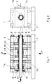
- the device according to the invention comprises a mounting block 1, in two parts 1a and 1b, assembling along the joint plane 2 generally passing through the axis 5.
- the mounting block 1 is placed between the 2 plates of a hydraulic press exerting a pressure P; each part 1a and 1b is secured to each of the plates by known means not shown.
- this mounting block 1 In this mounting block 1 are placed the parts such as 4a, 4b, 4c, whose bores are on the axis 5 of the tube 6.
- the device also includes a dudgeon 7 carried by a rod 8, connected to a displacement device, not shown, in the direction of arrow F.
- a removable stop 9 is positioned at the downstream end 6a of the tube 6. It is eclipsable by translation along the arrow F '.
- the stop 9 has an opening 10 in the form of a keyhole, the the widest part has a diameter greater than the outside diameter of the tube 6 and whose narrow part has a dimension less than the diameter inside of the tube 6. It slides in the added plate 12.
- the mounting block 1 is fixed to a sole 11 which also carries the traction cylinder (not shown).
- a steel tube 6 which has before expansion a thickness of 1.2 mm and an elastic limit E 0.2 in length equal to 400 MPa.
- This tube 6 has before expansion of the inside diameters and outside respectively 23.96 mm and 26.36 mm.
- the metal cams 4a, 4c being fixed on the tube 6 have been obtained by sintering and are made of steel at 0.85% Mo. Their bore cylindrical has a diameter of 26.54 mm and their thickness is 14 mm.
- the dudgeon 7 is made of sintered tungsten carbide; it includes a portion tapered inlet inclined at 10 ° on axis 5, starting at the diameter 23.6mm and connecting to its cylindrical portion with a diameter of 24.25mm.
- the pressure exerted by the hydraulic press plates is 1.5 MPa.
- the resistance to loosening in rotation of the cams 4a, 4c by compared to tube 6 on which they were thus shrunk was found equal to 70 N.m.
- each cam 4a, 4c carries ten regularly spaced longitudinal grooves 31.
- These grooves 31 have in cross section (fig.3) a semicircular contour of radius 0.4 mm connected to the smooth parts 32 of the bore by radiated portions 33 of radius 0.3 mm.
- the mounting block (1, 1a, 1b) made of steel with a hardness of 45 HRc.
- the pressure exerted by the hydraulic press plates at the joint plane (2) was 1.5 MPa.
- the bearing 40 is formed by the juxtaposition of the lateral parts 41a, 41c of the cams 4a and 4c. This part can be expanded (lower part of FIG. 4) or not (upper part of FIG. 4) on the tube 6.
- the mode offers a economic advantage over the prior art (removal of dressing and / or grinding operations); she is easily automatable, which contributes to its productivity and profitability.
- the invention finds its application mainly in the manufacture of camshafts.
Landscapes
- Engineering & Computer Science (AREA)
- General Engineering & Computer Science (AREA)
- Mechanical Engineering (AREA)
- Valve-Gear Or Valve Arrangements (AREA)
- Gears, Cams (AREA)
- Basic Packing Technique (AREA)
Claims (8)
- Vorrichtung zur Verbundfixierung wenigstens eines wenigstens eine Bohrung aufweisenden metallischen Werkstücks bzw. Metallteils (4a,4b,4c) auf einem von ihm umschlossenen Metallrohr (6) um dieses herum mit Hilfe eines längs der Achse (5) des Rohrs (6) translatorisch verschieblichen Expansions- bzw. Aufweitdorns (7), sowie mit Hilfe einer Halterungsvorrichtung (1) für die genannten Metallteile, wobei die Halterungsvorrichtung einen Montage-bzw. Halterungsblock (1) mit zwei miteinander verspannten Teilen (1a,1b) aufweist, in welchen die Ausnehmungen zur Aufnahme der Metallteile ausgeformt sind,
dadurch gekennzeichnet, daß
die Vorrichtung einen verschließ- bzw. verengerbaren Anschlag (9) aufweist, der in einer Aufsteckplatte (12) gleitend verschieblich ist, die an dem stromabwärtigen Ende des Montage- bzw. Halterungsblocks (1) angeordnet ist, bezogen auf die Vorschubrichtung des Expansions- bzw. Aufweitdorns (7) beim Expansions- bzw. Aufweitvorgang. - Verfahren zur Verbundfixierung wenigstens eines wenigstens eine Bohrung aufweisenden metallischen Werkstücks bzw. Teils (4a,4b,4c) auf einem Rohr (6), mit Hilfe eines translatorisch in Richtung der Achse (5) des Rohrs (6) verschieblichen Expansions- bzw. Aufweitdorns (7), wobei die Metallteile bzw. Werkstücke in einem Montage- bzw. Halterungsblock (1,1a,1b) gehaltert sind, der einen verschließ- bzw. verengerbaren Anschlag (9) aufweist, der in einer Platte (12) gleitend verschieblich ist, die an dem in Richtung der Vorschubbewegung des genannten Expansions- bzw.Aufweitdorns (7) stromabwärtigen Ende des genannten Montage- bzw. Halterungsblocks (1,1a,1b) angeordnet ist, wobei das Verfahren die folgenden Stufen umfaßt:(a) der Montage- bzw. Halterungsblock (1,1a,1b) wird zwischen den beiden Platten einer Presse, vorzugsweise einer Hydraulikpresse eingebracht, deren Preß-bzw, Schließdruck steuerbar ist, wobei die beiden Teile (1a,1b) der Halterungsvorrichtung jeweils mit der oberen bzw. der unteren Preßplatte fest verbunden werden,(b) in dem unteren Block (1b) des Halterungsblocks werden die verschiedenen Werkstücke bzw. Teile in ihre Aufnahmen eingesetzt,(c) der Montage bzw. Halterungsblock (1,1a,1b) wird mittels Aufbringung eines Preßdrucks von mehr als 1 MPa geschlossen,(d) das Rohr (6) wird in die Bohrungen bis zur Anlage gegen den verschließ- bzw. verengerbaren Anschlag (9) eingeführt,(e) die Zieh-bzw. Betätigungsstange (8) des Expansions- bzw. Aufweitdorns (7) wird in das Rohr (6) eingeführt und mit der Vorschub- bzw. Ziehvorrichtung gekuppelt,(f) der Expansions- bzw. Aufweitdorn (7) wird bis zu seinem vollständigen Eintritt in die erste Bohrung vorgeschoben,(g) der Anschlag (9) wird verschlossen bzw. verengt,(h) der Expansins- bzw. Aufweitvorgang wird bis zum freien Ende des Rohrs (6) fortgesetzt,(i) der Montage- bzw. Halterungsblock (1,1a,1b) wird geöffnet,(j) das fertige Werkstück bzw. Teil wird entnommen.
- Verfahren nach Anspruch 1, dadurch gekennzeichnet, daß die Werkstücke bzw. Teile (4a,4b,4c) an ihren Bohrungen in Abstand voneinander angeordnete Längsnuten (31) aufweisen.
- Verfahren nach Anspruch 3, dadurch gekennzeichnet, daß jeweils jede Nut (31) mit den glatten Teilen (32) der Bohrung (6) über abgerundete Bereiche (33) mit Krümmungsradius von 0,1 bis 0,5 mm verbunden ist.
- Verfahren nach Anspruch 4, dadurch gekennzeichnet, daß die genannten Nuten (31) jeweils in einer Anzahl von 3 bis 15 vorliegen, und daß sie jeweils, jenseits der abgerundten Bereiche (33), eine Innenbreite im Bereich zwischen 0,4 und 0,9 mm besitzen.
- Verfahren nach einem der Ansprüche 2 bis 5, bei welchem das Metallrohr (6) kreisförmigen Querschnitt und eine Wandstärke im Bereich zwischen 1 und 2,5 mm besitzt, und bei welchem der Expansions- bzw. Aufweitdorn einen solchen Gesamtdurchmesser (Außendurchmesser) besitzt, daß die Summe aus diesem Durchmesser und dem Zweifachen der genannten Wandstärke des Rohrs (6) wenigstens um 0,04 mm größer als der Durchmesser der Bohrungen der jeweiligen metallischen Werkstücke bzw. Teile (4a,4b,4c) ist.
- Verfahren nach Anspruch 6, bei welchem der Expansions- bzw. Aufweitdorn (7) einen kreiszylindrischen Umfang mit einem Außendurchmesser besitzt, der um 0,1 bis 0,5 mm größer als der Innendurchmesser des Metallrohrs (6) ist, und bei welchem das Spiel zwischen den Bohrungen der einzelnen metallischen Werkstücke (4a,4b,4c) bezüglich dem Rohr (6) 0,04 bis 0,2 mm in Durchmesserrichtung beträgt.
- Verfahren nach einem der Ansprüche 2 bis 7, dadurch gekennzeichnet, daß der auf die Verbindungs- bzw. Stoßebene des Montage- bzw. Halterungsblocks (1) aufgebrachte Druck größer als 1 MPa ist.
Applications Claiming Priority (2)
| Application Number | Priority Date | Filing Date | Title |
|---|---|---|---|
| FR9214348 | 1992-11-24 | ||
| FR9214348A FR2698303B1 (fr) | 1992-11-24 | 1992-11-24 | Procédé de frettage d'au moins une pièce métallique ayant un alésage annulaire autour d'un tube métallique, ensemble obtenu et utilisation du procédé. |
Publications (2)
| Publication Number | Publication Date |
|---|---|
| EP0599751A1 EP0599751A1 (de) | 1994-06-01 |
| EP0599751B1 true EP0599751B1 (de) | 1999-01-07 |
Family
ID=9436013
Family Applications (1)
| Application Number | Title | Priority Date | Filing Date |
|---|---|---|---|
| EP93420464A Expired - Lifetime EP0599751B1 (de) | 1992-11-24 | 1993-11-22 | Verfahren und Vorrichtung zum Fixieren eines mit zumindest einer zylindrischen Bohrung versehenen metallischen Stückes um ein metallisches Rohr |
Country Status (5)
| Country | Link |
|---|---|
| US (1) | US5504995A (de) |
| EP (1) | EP0599751B1 (de) |
| DE (1) | DE69322945T2 (de) |
| ES (1) | ES2129074T3 (de) |
| FR (1) | FR2698303B1 (de) |
Families Citing this family (5)
| Publication number | Priority date | Publication date | Assignee | Title |
|---|---|---|---|---|
| DE19625555C2 (de) * | 1996-06-26 | 1999-08-05 | Hans Dipl Ing Kuehl | Verfahren und Vorrichtung zum drehfesten Verbinden einer hohlen Welle mit mindestens einem auf der Welle angeordneten Teil |
| FR2784925B1 (fr) * | 1998-10-26 | 2001-01-19 | Fedreal Mogul Sintered Product | Dispositif de maintien de cames au cours de leur frettage sur un tube par expansion du tube |
| JP4075478B2 (ja) * | 2002-06-13 | 2008-04-16 | 日産自動車株式会社 | エンジン用組立式カムシャフトおよびその製造方法 |
| DE102009060348A1 (de) * | 2009-12-24 | 2011-06-30 | Volkswagen AG, 38440 | Montagevorrichtung und Verfahren zur Montage eines Wellen-Hauben-Moduls |
| CN114933257B (zh) * | 2022-04-18 | 2024-04-09 | 武汉船用机械有限责任公司 | 一种多片滑轮组装配设备 |
Family Cites Families (14)
| Publication number | Priority date | Publication date | Assignee | Title |
|---|---|---|---|---|
| US2892254A (en) * | 1953-06-08 | 1959-06-30 | American Radiator & Standard | Method of making cam shafts |
| GB1117816A (en) * | 1965-07-31 | 1968-06-26 | Gkn Screws Fasteners Ltd | Improvements relating to cam shafts |
| DE3302762A1 (de) * | 1982-08-11 | 1984-02-16 | Kokan Kako Co., Ltd., Yokohama, Kanagawa | Verfahren zur befestigung eines bauteils am aussenumfang eines rohrs |
| FR2541720B1 (fr) * | 1983-02-24 | 1987-05-22 | Citroen Sa | Arbre a cames frittees collees |
| JPS6033302A (ja) * | 1983-08-03 | 1985-02-20 | Nippon Piston Ring Co Ltd | カムシャフトの製造方法 |
| US4763503A (en) * | 1985-12-31 | 1988-08-16 | Hughes Robert W | Apparatus for making a cam shaft |
| US4781076A (en) * | 1986-01-17 | 1988-11-01 | The Torrington Company | Camshaft for reciprocating piston engines |
| DE3842591A1 (de) * | 1988-12-17 | 1990-06-21 | Emitec Emissionstechnologie | Verfahren zum herstellen von verbindungen |
| US5038596A (en) * | 1989-12-01 | 1991-08-13 | Grumman Aerospace Corporation | Threaded cold working mandrel |
| US5157832A (en) * | 1990-06-08 | 1992-10-27 | Hughes Robert W | Method of making a cam shaft from cam lobe having orientating means |
| US5085099A (en) * | 1990-06-08 | 1992-02-04 | Hughes Robert W | Cam lobe having orientating means |
| US5195229A (en) * | 1990-06-08 | 1993-03-23 | Hughes Robert W | CAM lobe having orientating means |
| US5220727A (en) * | 1992-06-25 | 1993-06-22 | Hochstein Peter A | Method making cam shafts |
| US5280675A (en) * | 1992-07-13 | 1994-01-25 | The Torrington Company | Camshaft and method of making a camshaft |
-
1992
- 1992-11-24 FR FR9214348A patent/FR2698303B1/fr not_active Expired - Fee Related
-
1993
- 1993-11-22 ES ES93420464T patent/ES2129074T3/es not_active Expired - Lifetime
- 1993-11-22 EP EP93420464A patent/EP0599751B1/de not_active Expired - Lifetime
- 1993-11-22 DE DE69322945T patent/DE69322945T2/de not_active Expired - Lifetime
- 1993-11-22 US US08/155,299 patent/US5504995A/en not_active Expired - Lifetime
Also Published As
| Publication number | Publication date |
|---|---|
| DE69322945D1 (de) | 1999-02-18 |
| DE69322945T2 (de) | 1999-08-12 |
| US5504995A (en) | 1996-04-09 |
| FR2698303A1 (fr) | 1994-05-27 |
| EP0599751A1 (de) | 1994-06-01 |
| ES2129074T3 (es) | 1999-06-01 |
| FR2698303B1 (fr) | 1994-12-23 |
Similar Documents
| Publication | Publication Date | Title |
|---|---|---|
| BE897900A (fr) | Liaison entre un premier élément et un alésage formé dans un second élément. | |
| FR2504427A1 (fr) | Mandrin de serrage avec douille de serrage dilatable hydrauliquement | |
| FR2483286A1 (fr) | Procede de fabrication d'un ensemble de tige de piston | |
| FR2638114A1 (fr) | Arbre a cames et son procede de fabrication | |
| FR2720977A1 (fr) | Procédé de montage d'un ensemble formé d'un pneumatique et d'un appui de soutien de bande de roulement. | |
| FR2523490A1 (fr) | Procede pour fixer axialement une roue dentee metallique sur un arbre metallique et element ainsi produit | |
| FR2544645A1 (fr) | Methode d'assemblage d'un element annulaire sur un tube metallique en aluminium ou un de ses alliages | |
| EP0599751B1 (de) | Verfahren und Vorrichtung zum Fixieren eines mit zumindest einer zylindrischen Bohrung versehenen metallischen Stückes um ein metallisches Rohr | |
| FR2633018A1 (fr) | Verin | |
| FR2580341A1 (fr) | Procede de realisation d'une liaison rigide entre deux pieces mecaniques coaxiales, et ensemble de deux pieces liees par ce procede | |
| FR3024123A1 (fr) | Procede de remise en conformite de jante et outillage pour la mise en œuvre du procede | |
| CH622857A5 (de) | ||
| EP3115226B1 (de) | Zentrierteil für ein radlager, entsprechendes radlager und entsprechende radanordnung eines fahrzeugs | |
| FR2495029A1 (fr) | Ensemble de cylindre de laminoir et procede de montage d'un cylindre sur laminoir | |
| FR2667684A1 (fr) | Procede de realisation d'un assemblage tube/fond pour un echangeur de chaleur. | |
| EP0019256B1 (de) | Muffenrohr aus Kugelgraphitguss | |
| FR2669087A1 (fr) | Bague exterieure de palier de roue. | |
| FR2678027A3 (en) | Cover fastening for pneumatic or hydraulic jack | |
| FR2474908A1 (fr) | Procede et dispositif d'extrusion en chambre fermee pour configurer une tige en metal en une piece en forme de tulipe | |
| FR3018104A1 (fr) | Procede d'assemblage d'un arbre a cames | |
| EP2106306A1 (de) | Vorrichtung zum biegen eines metallrohrs durch wickeln auf eine formrolle | |
| FR2610050A1 (fr) | Galet constitue d'une piece moulee et d'une douille | |
| EP1461171A1 (de) | Spreizverfahren und -vorrichtung und sich ergebendes gespreiztes elastisches gelenk | |
| FR2509211A1 (fr) | Procede de soudage de joints circulaires de tubes et dispositif pour la mise en oeuvre de ce procede | |
| FR2769253A1 (fr) | Dispositif de bridage rotatif pour l'usinage de profile |
Legal Events
| Date | Code | Title | Description |
|---|---|---|---|
| PUAI | Public reference made under article 153(3) epc to a published international application that has entered the european phase |
Free format text: ORIGINAL CODE: 0009012 |
|
| AK | Designated contracting states |
Kind code of ref document: A1 Designated state(s): DE ES FR GB IT SE |
|
| 17P | Request for examination filed |
Effective date: 19940623 |
|
| 17Q | First examination report despatched |
Effective date: 19951023 |
|
| GRAG | Despatch of communication of intention to grant |
Free format text: ORIGINAL CODE: EPIDOS AGRA |
|
| GRAG | Despatch of communication of intention to grant |
Free format text: ORIGINAL CODE: EPIDOS AGRA |
|
| GRAH | Despatch of communication of intention to grant a patent |
Free format text: ORIGINAL CODE: EPIDOS IGRA |
|
| GRAH | Despatch of communication of intention to grant a patent |
Free format text: ORIGINAL CODE: EPIDOS IGRA |
|
| GRAA | (expected) grant |
Free format text: ORIGINAL CODE: 0009210 |
|
| AK | Designated contracting states |
Kind code of ref document: B1 Designated state(s): DE ES FR GB IT SE |
|
| REF | Corresponds to: |
Ref document number: 69322945 Country of ref document: DE Date of ref document: 19990218 |
|
| ITF | It: translation for a ep patent filed | ||
| GBT | Gb: translation of ep patent filed (gb section 77(6)(a)/1977) |
Effective date: 19990330 |
|
| REG | Reference to a national code |
Ref country code: ES Ref legal event code: FG2A Ref document number: 2129074 Country of ref document: ES Kind code of ref document: T3 |
|
| PLBE | No opposition filed within time limit |
Free format text: ORIGINAL CODE: 0009261 |
|
| STAA | Information on the status of an ep patent application or granted ep patent |
Free format text: STATUS: NO OPPOSITION FILED WITHIN TIME LIMIT |
|
| 26N | No opposition filed | ||
| REG | Reference to a national code |
Ref country code: GB Ref legal event code: IF02 |
|
| REG | Reference to a national code |
Ref country code: FR Ref legal event code: TP Ref country code: FR Ref legal event code: CD Ref country code: FR Ref legal event code: CA |
|
| REG | Reference to a national code |
Ref country code: FR Ref legal event code: TP |
|
| REG | Reference to a national code |
Ref country code: GB Ref legal event code: 732E |
|
| REG | Reference to a national code |
Ref country code: GB Ref legal event code: 732E |
|
| REG | Reference to a national code |
Ref country code: FR Ref legal event code: CD |
|
| REG | Reference to a national code |
Ref country code: ES Ref legal event code: PC2A |
|
| REG | Reference to a national code |
Ref country code: GB Ref legal event code: 732E Free format text: REGISTERED BETWEEN 20090618 AND 20090624 |
|
| REG | Reference to a national code |
Ref country code: FR Ref legal event code: ST Effective date: 20090731 |
|
| REG | Reference to a national code |
Ref country code: FR Ref legal event code: TP |
|
| REG | Reference to a national code |
Ref country code: ES Ref legal event code: PC2A |
|
| REG | Reference to a national code |
Ref country code: FR Ref legal event code: RN |
|
| REG | Reference to a national code |
Ref country code: FR Ref legal event code: FC |
|
| PGFP | Annual fee paid to national office [announced via postgrant information from national office to epo] |
Ref country code: SE Payment date: 20091127 Year of fee payment: 17 Ref country code: ES Payment date: 20091126 Year of fee payment: 17 Ref country code: DE Payment date: 20091127 Year of fee payment: 17 |
|
| PGFP | Annual fee paid to national office [announced via postgrant information from national office to epo] |
Ref country code: IT Payment date: 20091128 Year of fee payment: 17 Ref country code: GB Payment date: 20091125 Year of fee payment: 17 |
|
| PGFP | Annual fee paid to national office [announced via postgrant information from national office to epo] |
Ref country code: FR Payment date: 20100406 Year of fee payment: 17 |
|
| REG | Reference to a national code |
Ref country code: SE Ref legal event code: EUG |
|
| GBPC | Gb: european patent ceased through non-payment of renewal fee |
Effective date: 20101122 |
|
| REG | Reference to a national code |
Ref country code: FR Ref legal event code: ST Effective date: 20110801 |
|
| REG | Reference to a national code |
Ref country code: DE Ref legal event code: R119 Ref document number: 69322945 Country of ref document: DE Effective date: 20110601 Ref country code: DE Ref legal event code: R119 Ref document number: 69322945 Country of ref document: DE Effective date: 20110531 |
|
| PG25 | Lapsed in a contracting state [announced via postgrant information from national office to epo] |
Ref country code: SE Free format text: LAPSE BECAUSE OF NON-PAYMENT OF DUE FEES Effective date: 20101123 Ref country code: DE Free format text: LAPSE BECAUSE OF NON-PAYMENT OF DUE FEES Effective date: 20110531 |
|
| PG25 | Lapsed in a contracting state [announced via postgrant information from national office to epo] |
Ref country code: FR Free format text: LAPSE BECAUSE OF NON-PAYMENT OF DUE FEES Effective date: 20101130 |
|
| PG25 | Lapsed in a contracting state [announced via postgrant information from national office to epo] |
Ref country code: GB Free format text: LAPSE BECAUSE OF NON-PAYMENT OF DUE FEES Effective date: 20101122 |
|
| PG25 | Lapsed in a contracting state [announced via postgrant information from national office to epo] |
Ref country code: IT Free format text: LAPSE BECAUSE OF NON-PAYMENT OF DUE FEES Effective date: 20101122 |
|
| REG | Reference to a national code |
Ref country code: ES Ref legal event code: FD2A Effective date: 20120110 |
|
| PG25 | Lapsed in a contracting state [announced via postgrant information from national office to epo] |
Ref country code: ES Free format text: LAPSE BECAUSE OF NON-PAYMENT OF DUE FEES Effective date: 20101123 |