EP0600189B1 - Echangeur de chaleur à plaques - Google Patents
Echangeur de chaleur à plaques Download PDFInfo
- Publication number
- EP0600189B1 EP0600189B1 EP93116278A EP93116278A EP0600189B1 EP 0600189 B1 EP0600189 B1 EP 0600189B1 EP 93116278 A EP93116278 A EP 93116278A EP 93116278 A EP93116278 A EP 93116278A EP 0600189 B1 EP0600189 B1 EP 0600189B1
- Authority
- EP
- European Patent Office
- Prior art keywords
- plate
- heat
- heat exchanger
- exchanger
- plates
- Prior art date
- Legal status (The legal status is an assumption and is not a legal conclusion. Google has not performed a legal analysis and makes no representation as to the accuracy of the status listed.)
- Expired - Lifetime
Links
- 230000008878 coupling Effects 0.000 claims description 20
- 238000010168 coupling process Methods 0.000 claims description 20
- 238000005859 coupling reaction Methods 0.000 claims description 20
- 239000012790 adhesive layer Substances 0.000 claims description 3
- 230000002093 peripheral effect Effects 0.000 claims 1
- 239000000853 adhesive Substances 0.000 description 7
- 230000001070 adhesive effect Effects 0.000 description 7
- 238000012423 maintenance Methods 0.000 description 2
- 239000002184 metal Substances 0.000 description 2
- 230000007935 neutral effect Effects 0.000 description 2
- 230000000284 resting effect Effects 0.000 description 2
- 230000002950 deficient Effects 0.000 description 1
- 238000006073 displacement reaction Methods 0.000 description 1
- 239000003292 glue Substances 0.000 description 1
Images
Classifications
-
- F—MECHANICAL ENGINEERING; LIGHTING; HEATING; WEAPONS; BLASTING
- F28—HEAT EXCHANGE IN GENERAL
- F28F—DETAILS OF HEAT-EXCHANGE AND HEAT-TRANSFER APPARATUS, OF GENERAL APPLICATION
- F28F3/00—Plate-like or laminated elements; Assemblies of plate-like or laminated elements
- F28F3/08—Elements constructed for building-up into stacks, e.g. capable of being taken apart for cleaning
- F28F3/083—Elements constructed for building-up into stacks, e.g. capable of being taken apart for cleaning capable of being taken apart
-
- F—MECHANICAL ENGINEERING; LIGHTING; HEATING; WEAPONS; BLASTING
- F28—HEAT EXCHANGE IN GENERAL
- F28D—HEAT-EXCHANGE APPARATUS, NOT PROVIDED FOR IN ANOTHER SUBCLASS, IN WHICH THE HEAT-EXCHANGE MEDIA DO NOT COME INTO DIRECT CONTACT
- F28D9/00—Heat-exchange apparatus having stationary plate-like or laminated conduit assemblies for both heat-exchange media, the media being in contact with different sides of a conduit wall
- F28D9/0031—Heat-exchange apparatus having stationary plate-like or laminated conduit assemblies for both heat-exchange media, the media being in contact with different sides of a conduit wall the conduits for one heat-exchange medium being formed by paired plates touching each other
- F28D9/0043—Heat-exchange apparatus having stationary plate-like or laminated conduit assemblies for both heat-exchange media, the media being in contact with different sides of a conduit wall the conduits for one heat-exchange medium being formed by paired plates touching each other the plates having openings therein for circulation of at least one heat-exchange medium from one conduit to another
- F28D9/005—Heat-exchange apparatus having stationary plate-like or laminated conduit assemblies for both heat-exchange media, the media being in contact with different sides of a conduit wall the conduits for one heat-exchange medium being formed by paired plates touching each other the plates having openings therein for circulation of at least one heat-exchange medium from one conduit to another the plates having openings therein for both heat-exchange media
Definitions
- the invention relates to a plate heat exchanger comprising a plurality of heat exchanger plates, each of which is arranged in pairs with the interposition of a circumferential seal designed as a ring, the one medium participating in the heat exchange in the flow channels formed between a pair of plates and the other medium participating in the heat exchange in those flow channels flows, which are formed between adjacent plate pairs, and the seals are arranged in receptacles designed for this purpose on both sides of the heat exchanger plates.
- the invention has for its object to develop the seals for a plate heat exchanger of the type described in such a way that they can be attached to the prescribed locations of the heat exchanger plates without the use of adhesive and are reliably held there until the plate pack is completed.
- the solution to this problem by the invention is characterized in that the seals lying on the two sides of a heat exchanger plate are connected in pairs by connecting elements encompassing one edge of the heat exchanger plate and can be connected to one another by at least one of the three other edges arranged coupling elements.
- the seals in the plate heat exchanger according to the invention are not glued to one side of each heat exchanger plate, but rather are attached as pairs of seals to both sides of a heat exchanger plate without the use of adhesive.
- the seals firmly connected to one another by connecting elements are put over the plate and connected to one another at least on one of the three other edges via coupling elements formed there.
- the connecting elements and the coupling elements ensure that the seals are held securely in the receptacles formed on both sides of the plate, so that adjacent heat exchanger plates are reliably sealed.
- the heat exchanger plates which are not provided with seals, lay down when the plates are joined together to form a plate pack with their receptacles provided for the seals on the seal arranged on the adjacent heat exchanger plate in such a way that the flow channels formed between adjacent heat exchanger plates are sealed on all sides. Since no adhesive has to be used to fix the seals between the heat exchanger plates, not only are harmful influences due to this adhesive avoided, but also problems when replacing defective seals are avoided, which often cannot be completely removed from the heat exchanger plate or through when using adhesive the glue had been destroyed or attacked.
- the connecting elements are each formed from two legs which are offset from one another on one side of the associated heat exchanger plate and a web connecting the legs and extending outside the edge of the heat exchanger plate. This configuration ensures that the connecting elements on the one hand do not impede the joining of the heat exchanger plates and on the other hand maintain the paired connection of the seals when the plate heat exchanger is dismantled.
- the coupling elements are each formed from a transverse web resting on one side of the heat exchanger plate and a coupling plate running outside the edge of the heat exchanger plate, which can be connected to the coupling plate of the associated coupling element.
- this connection can preferably be made releasably by means of an adhesive layer, by at least one mechanical holding element, for example a metal clip, or by integrally molded holding elements, for example in the form of a push-button connection.
- the invention proposes to assemble the heat exchanger plates arranged in pairs in pressure-tight manner to form a plate pack by means of tie rods running at right angles to the heat exchanger plates. This results in a plate heat exchanger, the plate pack of which is screwed together by means of the tie rods, so that the plate pack can be dismantled in a particularly simple manner for repair and maintenance work.
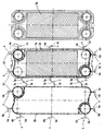
- an embodiment of the plate heat exchanger according to the invention is shown using a plan view of a heat exchanger plate provided with a pair of seals and onto a sealless plate.
- the plate heat exchanger not shown in its entirety, consists of two types of heat exchanger plates 1a and 1b, which are each connected in pairs to form a plate pair and form flow channels between them for the medium participating in the heat exchange.
- the other medium participating in the heat exchange flows through flow channels which are formed between the heat exchanger plates 1a and 1b of adjacent plate pairs.
- a circumferential seal 2a and 2b which is designed as a ring, is arranged in each case.
- These seals 2a and 2b are located in receptacles of the heat exchanger plates 1a and 1b designed for this purpose in such a way that the seals 2a and 2b are arranged in the neutral plane of the heat exchanger plates 1a and 1b, this neutral plane being through the center of the a plate pair connected individual plates is formed.
- the seals 2a and 2b are connected to one another in pairs. At one edge, a fixed connection is created by connecting elements 3 between the seals 2a and 2b of a pair of seals.
- These connecting elements 3 each consist of two legs 3a, which are each formed on the outside of the seal 2a or 2b offset with respect to one another and are connected to one another by an inclined web 3b.
- the legs 3a each lie on one side of the heat exchanger plate 1a, whereas the web 3b extends outside the edge of the heat exchanger plate 1a parallel to this edge as soon as the seal 2b visible in the drawing on the left on the underside of the heat exchanger plate 1a has been placed by folding.
- the three other edges of the two seals 2a and 2b are connected to one another by coupling elements 4, each of which is formed from a transverse web 4a resting on one side of the heat exchanger plate 1a and a coupling bracket 4b projecting at right angles therefrom.
- the coupling tabs 4b of the transverse webs 4a which are in turn offset from one another, lie against one another and can thus be connected to one another in a simple manner.
- the coupling tabs 4b which belong together, are detachably connected either by an adhesive layer, by a mechanical holding element, such as a metal clip, or by holding elements integrally formed on the coupling tabs 4b, for example in the form of a push button.
Landscapes
- Engineering & Computer Science (AREA)
- Physics & Mathematics (AREA)
- Thermal Sciences (AREA)
- Mechanical Engineering (AREA)
- General Engineering & Computer Science (AREA)
- Heat-Exchange Devices With Radiators And Conduit Assemblies (AREA)
Claims (5)
- Echangeur de chaleur à plaques constitué d'une pluralité de plaques d'échange de chaleur (1a, 1b) qui sont disposées par paires avec un joint périphérique (2a, 2b) intercalé en forme d'anneau, l'un des milieux participant à l'échange thermique circulant dans les canaux d'écoulement formés entre une paire de plaques, et l'autre milieu participant à l'échange thermique circulant dans les canaux d'écoulement formés entre des paires de plaques voisines, les joints étant disposés dans des logements ménagés à cet effet dans les deux faces des plaques d'échange de chaleur, caractérisé en ce que les joints (2a, 2b) appliqués sur les deux faces d'une plaque d'échange de chaleur (1a) sont solidarisés entre eux par paires à l'aide d'éléments de liaison (3) entourant un bord de la plaque d'échange de chaleur (1a) et peuvent être solidarisés entre eux par des éléments d'accouplement (4) disposés au moins dans la zone de l'un des trois bords.
- Echangeur de chaleur à plaques selon la revendication 1, caractérisé en ce que les éléments de liaison (3) sont formés chacun de deux branches (3a) appliquées avec un décalage mutuel sur l'une des faces de la plaque d'échange de chaleur correspondante (1) et d'une barrette (3b) qui relie les branches (3a) et qui s'étend à l'extérieur du bord de la plaque d'échange de chaleur (1a).
- Echangeur de chaleur à plaques selon la revendication 1 ou 2, caractérisé en ce que les éléments d'accouplement (4) sont formés chacun d'une barrette transversale (4a) appliquée contre une face de la plaque d'échange de chaleur (1a) et d'une patte d'accouplement (4b) qui s'étend à l'extérieur du bord de la plaque d'échange de chaleur (1a) et peut être reliée à la patte d'accouplement (4b) de l'élément d'accouplement correspondant (4).
- Echangeur de chaleur à plaques selon la revendication 3, caractérisé en ce que les pattes d'accouplement (4b) sont reliées entre elles de manière détachable au moyen d'une couche d'adhésif, d'au moins un élément mécanique de retenue ou d'éléments de retenue moulés d'une seule pièce.
- Echangeur de chaleur à plaques selon au moins une des revendications 1 à 4, caractérisé en ce que les plaques d'échange de chaleur (1a, 1b) disposées par paires soient assemblées de manière étanche à la pression en un paquet de plaques au moyen de tirants d'ancrage perpendiculaires aux plaques d'échange de chaleur (1a, 1b).
Applications Claiming Priority (2)
| Application Number | Priority Date | Filing Date | Title |
|---|---|---|---|
| DE4239049 | 1992-11-20 | ||
| DE4239049A DE4239049C1 (de) | 1992-11-20 | 1992-11-20 | Plattenwärmetauscher |
Publications (2)
| Publication Number | Publication Date |
|---|---|
| EP0600189A1 EP0600189A1 (fr) | 1994-06-08 |
| EP0600189B1 true EP0600189B1 (fr) | 1996-02-21 |
Family
ID=6473267
Family Applications (1)
| Application Number | Title | Priority Date | Filing Date |
|---|---|---|---|
| EP93116278A Expired - Lifetime EP0600189B1 (fr) | 1992-11-20 | 1993-10-08 | Echangeur de chaleur à plaques |
Country Status (3)
| Country | Link |
|---|---|
| EP (1) | EP0600189B1 (fr) |
| DE (2) | DE4239049C1 (fr) |
| ES (1) | ES2085702T3 (fr) |
Families Citing this family (3)
| Publication number | Priority date | Publication date | Assignee | Title |
|---|---|---|---|---|
| SE516178C2 (sv) | 2000-03-07 | 2001-11-26 | Alfa Laval Ab | Värmeöverföringsplatta, plattpaket, plattvärmväxlare samt användning av platta respektive plattpaket för framställning av plattvärmeväxlare |
| SE534765C2 (sv) * | 2010-04-21 | 2011-12-13 | Alfa Laval Corp Ab | Plattvärmeväxlareplatta och plattvärmeväxlare |
| CN106705717B (zh) * | 2017-01-19 | 2019-02-22 | 睿能太宇(沈阳)能源技术有限公司 | 一种特殊结构的圆形波纹板容积式换热器 |
Family Cites Families (5)
| Publication number | Priority date | Publication date | Assignee | Title |
|---|---|---|---|---|
| GB2145511B (en) * | 1983-08-23 | 1986-09-03 | Apv Int Ltd | Improved heat transfer apparatus |
| DD271947A1 (de) * | 1988-05-18 | 1989-09-20 | Kyffhaeuserhuette Maschf | Plattenwaermeuebertrager |
| DE4031355C2 (de) * | 1990-10-04 | 1994-03-24 | Balcke Duerr Ag | Plattenwärmetauscher |
| DE4037969A1 (de) * | 1990-11-29 | 1992-06-04 | Schmidt Bretten W Gmbh | Plattenwaermeaustauscher |
| DE4100940C1 (fr) * | 1991-01-15 | 1991-11-21 | Balcke-Duerr Ag, 4030 Ratingen, De |
-
1992
- 1992-11-20 DE DE4239049A patent/DE4239049C1/de not_active Expired - Fee Related
-
1993
- 1993-10-08 DE DE59301679T patent/DE59301679D1/de not_active Expired - Fee Related
- 1993-10-08 EP EP93116278A patent/EP0600189B1/fr not_active Expired - Lifetime
- 1993-10-08 ES ES93116278T patent/ES2085702T3/es not_active Expired - Lifetime
Also Published As
| Publication number | Publication date |
|---|---|
| EP0600189A1 (fr) | 1994-06-08 |
| DE59301679D1 (de) | 1996-03-28 |
| ES2085702T3 (es) | 1996-06-01 |
| DE4239049C1 (de) | 1993-10-14 |
Similar Documents
| Publication | Publication Date | Title |
|---|---|---|
| EP0578933B1 (fr) | Echangeur de chaleur à plaques soudées | |
| DE69101297T2 (de) | Plattenwärmetauscher. | |
| DE60110757T2 (de) | Plattenpaket für einen Plattenwärmetauscher | |
| CH644945A5 (de) | Waermetauscher. | |
| DE2840522A1 (de) | Plattenwaermetauscher | |
| DE19858652A1 (de) | Plattenwärmeaustauscher | |
| DE69101814T2 (de) | Plattenwärmetauscher. | |
| DE2948586A1 (de) | Plattenwaermeaustauscher | |
| DE2905001C2 (de) | Rohrbündelwärmetauscher | |
| EP0600189B1 (fr) | Echangeur de chaleur à plaques | |
| EP0658735B1 (fr) | Echangeur de chaleur à plaques | |
| DE3341361C2 (de) | Radiator, insbesondere für Klimaanlagen von Kraftfahrzeugen | |
| DE69506541T2 (de) | Plattenwärmetauscher | |
| DE3332159C2 (de) | Verfahren zum Herstellen eines Plattenwärmetauschers | |
| DE3634113C2 (fr) | ||
| DE3047411C2 (de) | Wärmeaustauscher | |
| DE29504526U1 (de) | Wärmeaustauscher, insbesondere für Kraftfahrzeuge | |
| EP0167993A2 (fr) | Echangeur de chaleur construit à partir de plaques | |
| DE4031355C2 (de) | Plattenwärmetauscher | |
| DE2139364B2 (de) | Trennwand fuer einen wasserkasten eines waermetauschers | |
| DE2525921A1 (de) | Waermeaustauscher | |
| AT281082B (de) | Plattenwärmeaustauscher | |
| DE2617261C2 (de) | Wärmeaustauscher | |
| DE19628390C1 (de) | Plattenwärmetauscher | |
| EP0235797A1 (fr) | Dispositif d'accouplement |
Legal Events
| Date | Code | Title | Description |
|---|---|---|---|
| PUAI | Public reference made under article 153(3) epc to a published international application that has entered the european phase |
Free format text: ORIGINAL CODE: 0009012 |
|
| 17P | Request for examination filed |
Effective date: 19940226 |
|
| AK | Designated contracting states |
Kind code of ref document: A1 Designated state(s): DE ES FR GB IT SE |
|
| RAP1 | Party data changed (applicant data changed or rights of an application transferred) |
Owner name: BDAG BALCKE-DUERR AKTIENGESELLSCHAFT |
|
| 17Q | First examination report despatched |
Effective date: 19950814 |
|
| GRAA | (expected) grant |
Free format text: ORIGINAL CODE: 0009210 |
|
| AK | Designated contracting states |
Kind code of ref document: B1 Designated state(s): DE ES FR GB IT SE |
|
| ET | Fr: translation filed | ||
| GBT | Gb: translation of ep patent filed (gb section 77(6)(a)/1977) |
Effective date: 19960221 |
|
| REF | Corresponds to: |
Ref document number: 59301679 Country of ref document: DE Date of ref document: 19960328 |
|
| ITF | It: translation for a ep patent filed | ||
| REG | Reference to a national code |
Ref country code: ES Ref legal event code: FG2A Ref document number: 2085702 Country of ref document: ES Kind code of ref document: T3 |
|
| PGFP | Annual fee paid to national office [announced via postgrant information from national office to epo] |
Ref country code: FR Payment date: 19960916 Year of fee payment: 4 |
|
| PGFP | Annual fee paid to national office [announced via postgrant information from national office to epo] |
Ref country code: SE Payment date: 19961021 Year of fee payment: 4 |
|
| PGFP | Annual fee paid to national office [announced via postgrant information from national office to epo] |
Ref country code: ES Payment date: 19961031 Year of fee payment: 4 |
|
| PGFP | Annual fee paid to national office [announced via postgrant information from national office to epo] |
Ref country code: DE Payment date: 19961218 Year of fee payment: 4 |
|
| PLBE | No opposition filed within time limit |
Free format text: ORIGINAL CODE: 0009261 |
|
| STAA | Information on the status of an ep patent application or granted ep patent |
Free format text: STATUS: NO OPPOSITION FILED WITHIN TIME LIMIT |
|
| 26N | No opposition filed | ||
| PG25 | Lapsed in a contracting state [announced via postgrant information from national office to epo] |
Ref country code: GB Free format text: LAPSE BECAUSE OF NON-PAYMENT OF DUE FEES Effective date: 19971008 |
|
| PG25 | Lapsed in a contracting state [announced via postgrant information from national office to epo] |
Ref country code: SE Free format text: LAPSE BECAUSE OF NON-PAYMENT OF DUE FEES Effective date: 19971009 Ref country code: ES Free format text: LAPSE BECAUSE OF NON-PAYMENT OF DUE FEES Effective date: 19971009 |
|
| PG25 | Lapsed in a contracting state [announced via postgrant information from national office to epo] |
Ref country code: FR Free format text: THE PATENT HAS BEEN ANNULLED BY A DECISION OF A NATIONAL AUTHORITY Effective date: 19971031 |
|
| GBPC | Gb: european patent ceased through non-payment of renewal fee |
Effective date: 19971008 |
|
| PG25 | Lapsed in a contracting state [announced via postgrant information from national office to epo] |
Ref country code: DE Free format text: LAPSE BECAUSE OF NON-PAYMENT OF DUE FEES Effective date: 19980701 |
|
| EUG | Se: european patent has lapsed |
Ref document number: 93116278.8 |
|
| REG | Reference to a national code |
Ref country code: FR Ref legal event code: ST |
|
| REG | Reference to a national code |
Ref country code: ES Ref legal event code: FD2A Effective date: 19981113 |
|
| PG25 | Lapsed in a contracting state [announced via postgrant information from national office to epo] |
Ref country code: IT Free format text: LAPSE BECAUSE OF NON-PAYMENT OF DUE FEES;WARNING: LAPSES OF ITALIAN PATENTS WITH EFFECTIVE DATE BEFORE 2007 MAY HAVE OCCURRED AT ANY TIME BEFORE 2007. THE CORRECT EFFECTIVE DATE MAY BE DIFFERENT FROM THE ONE RECORDED. Effective date: 20051008 |