EP0658735B1 - Echangeur de chaleur à plaques - Google Patents
Echangeur de chaleur à plaques Download PDFInfo
- Publication number
- EP0658735B1 EP0658735B1 EP94119556A EP94119556A EP0658735B1 EP 0658735 B1 EP0658735 B1 EP 0658735B1 EP 94119556 A EP94119556 A EP 94119556A EP 94119556 A EP94119556 A EP 94119556A EP 0658735 B1 EP0658735 B1 EP 0658735B1
- Authority
- EP
- European Patent Office
- Prior art keywords
- plate
- plates
- channel
- individual
- heat exchanger
- Prior art date
- Legal status (The legal status is an assumption and is not a legal conclusion. Google has not performed a legal analysis and makes no representation as to the accuracy of the status listed.)
- Expired - Lifetime
Links
- 230000000994 depressogenic effect Effects 0.000 claims 1
- 238000004049 embossing Methods 0.000 description 23
- 230000007423 decrease Effects 0.000 description 2
- 238000006073 displacement reaction Methods 0.000 description 1
Images
Classifications
-
- F—MECHANICAL ENGINEERING; LIGHTING; HEATING; WEAPONS; BLASTING
- F28—HEAT EXCHANGE IN GENERAL
- F28F—DETAILS OF HEAT-EXCHANGE AND HEAT-TRANSFER APPARATUS, OF GENERAL APPLICATION
- F28F3/00—Plate-like or laminated elements; Assemblies of plate-like or laminated elements
- F28F3/02—Elements or assemblies thereof with means for increasing heat-transfer area, e.g. with fins, with recesses, with corrugations
- F28F3/04—Elements or assemblies thereof with means for increasing heat-transfer area, e.g. with fins, with recesses, with corrugations the means being integral with the element
- F28F3/042—Elements or assemblies thereof with means for increasing heat-transfer area, e.g. with fins, with recesses, with corrugations the means being integral with the element in the form of local deformations of the element
-
- F—MECHANICAL ENGINEERING; LIGHTING; HEATING; WEAPONS; BLASTING
- F28—HEAT EXCHANGE IN GENERAL
- F28D—HEAT-EXCHANGE APPARATUS, NOT PROVIDED FOR IN ANOTHER SUBCLASS, IN WHICH THE HEAT-EXCHANGE MEDIA DO NOT COME INTO DIRECT CONTACT
- F28D9/00—Heat-exchange apparatus having stationary plate-like or laminated conduit assemblies for both heat-exchange media, the media being in contact with different sides of a conduit wall
- F28D9/0031—Heat-exchange apparatus having stationary plate-like or laminated conduit assemblies for both heat-exchange media, the media being in contact with different sides of a conduit wall the conduits for one heat-exchange medium being formed by paired plates touching each other
- F28D9/0037—Heat-exchange apparatus having stationary plate-like or laminated conduit assemblies for both heat-exchange media, the media being in contact with different sides of a conduit wall the conduits for one heat-exchange medium being formed by paired plates touching each other the conduits for the other heat-exchange medium also being formed by paired plates touching each other
Definitions
- the invention relates to a plate heat exchanger with channels through which a cross flow flows, which are formed for the medium in a wave shape between individual plates each connected to a plate pair and for the other medium in a tube form between the plate pairs joined to form a plate stack, the individual plates having a plurality of parallel rows of in the flow direction of the medium-running, channel-shaped embossing sections are provided and the individual plates are connected to one another at the edges running transversely to the channel-shaped embossing sections to form pairs of plates and the plate pairs are connected to a stack of plates at the respective other edges of the individual plates (see, for example, DE-A-3 637 796) .
- Such plate heat exchangers are known. Since the trough-shaped embossing sections run parallel next to one another over the entire surface of the single plate, rectangular support fields result over the entire length or over the entire width of the individual plates if the plates of the plate stack also coincide due to a pressure difference between the two media participating in the heat transfer Pressure. While the support field width of the corrugated channels running between individual plates connected to a pair of plates corresponds to the center distance between the rows of the parallel groove-shaped embossing sections and is therefore relatively small, support field widths result for the tubular channels that are formed between adjacent plate pairs correspond to the length of the groove-shaped embossing sections.
- the invention has for its object to avoid the risk of such permanent deformations due to insufficient support of the individual plates against each other and to further develop a plate heat exchanger of the type described in the introduction in such a way that its individual plates are not subjected to inadmissibly high deformation forces even with larger pressure differences.
- the solution to this problem by the invention is characterized in that the groove-shaped embossing sections of adjacent rows are offset from one another in the longitudinal direction.
- each individual plate with at least one characteristic formed between adjacent rows of channel-shaped embossed sections, and this is also reduced to zero and, as a result, the flow cross-section of the undulating channels decreases to zero.
- each individual plate can be formed with at least one corresponding elevation and depression in the region of the groove-shaped embossing sections. These ridges and depressions interlock when plate pairs are joined to form the plate stack and in this way prevent the plate pairs from slipping transversely to the longitudinal direction of the channel-shaped embossed sections.
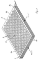
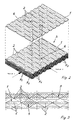
- the plate heat exchanger shown in FIG. 1 on the basis of a plate stack formed by five plate pairs consists of identical individual plates 1, each of which is connected in mirror image to one another to form a plate pair P. This connection takes place at the longitudinal edges la of the individual plates 1, a corrugated channel K 1 for the medium 1 participating in the heat exchange being produced between the individual plates 1 forming a pair of plates P in each case. This undulating course of the channel K 1 can be seen in the sectional view of FIGS. 2 and 4.
- tubular ducts K 2 for the other medium 2 participating in the heat exchange which is guided in cross flow to the medium 1, result between the adjacent individual plates 1 of adjacent plate pairs P.
- the flow cross section of these rectilinear, tubular channels K 2 can also be seen in FIGS. 2 and 4. 1 shows that the individual plates 1 connected to form plate pairs P are connected to one another at their edges 1b running transversely to the longitudinal edges la to form the plate stack S.
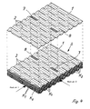
- each individual plate 1 is provided with a plurality of parallel rows of channel-shaped embossing sections 2 running in the flow direction of the medium 2, which can also be seen in the top view in FIG. 3 are.
- These embossed sections 2 of adjacent rows are offset from one another in the longitudinal direction. This results in flat supports 3 between adjacent individual plates 1 between embossing sections 2 which follow one another and which are symbolized in FIG. 3 by dots.
- These supports 3 form diamond-shaped, uniformly distributed support fields 4 of small dimensions over the entire surface of the individual plates 1, so that even with a higher overpressure in the tubular channels K 2 a reliable support of adjacent individual plates 1 is achieved and even at high differential pressures no permanent deformations of the Single plates 1 are to be feared.
- a strip-shaped support field 5 is further characterized, which results when the individual plates 1 are loaded by overpressing in the undulating channels K 1 .
- the small width of these strip-shaped support fields 5 shows that there is no fear of an inadmissibly high deformation of the individual plates 1 even if the corrugated channels K 1 are overpressed.
- each individual plate 1 is channel-shaped with one between adjacent rows Embossing sections 2 formed expression 6 provided.
- Embossing sections 2 formed expression 6 provided.
- This form-fitting engagement of the expression 6 between the embossing sections 2 prevents adjacent plate pairs P from slipping transversely to the longitudinal direction of the channel-shaped embossing sections 2, so that a reduction in the flow cross section of the tubular channels K 2 is reliably prevented.
- each individual plate 1 is provided with at least one elevation 7 in the region of a groove-shaped embossing section 2, which interacts with a corresponding depression 8 when the individual plates 1 of adjacent plate pairs P touching one another are joined, as shown in FIG. 4.
- This engagement of the corresponding elevations 7 and depressions 8 in the region of the trough-shaped embossing sections 2 likewise results in a positive connection of these individual plates 1, so that slipping of the plate pairs P transverse to the longitudinal direction of the trough-shaped embossing sections 2 is prevented.
Landscapes
- Engineering & Computer Science (AREA)
- Physics & Mathematics (AREA)
- Thermal Sciences (AREA)
- Mechanical Engineering (AREA)
- General Engineering & Computer Science (AREA)
- Heat-Exchange Devices With Radiators And Conduit Assemblies (AREA)
Claims (3)
- Echangeur de chaleur à plaques avec des canaux qui sont traversés par des courants croisés et qui sont conçus, pour le premier fluide, ondulés entre des plaques individuelles réunies en une paire de plaques et, pour l'autre fluide, tubulaires entre les paires de plaques assemblées en un empilement de plaques, sachant que les plaques individuelles sont munies de plusieurs rangées parallèles de parties matricées en forme de rigoles et s'étendant dans le sens d'écoulement du premier fluide, que les plaques individuelles sont réunies, au niveau de leurs bords perpendiculaires aux parties matricées en forme de rigoles, afin de former des paires de plaques, et que les paires de plaques sont réunies, au niveau des autres bords des plaques individuelles, afin de former un empilement de plaques,
caractérisé par le fait que
les parties matricées (2) de rangées voisines sont décalées les unes par rapport aux autres dans le sens de la longueur. - Echangeur de chaleur à plaques selon la revendication 1, caractérisé par le fait que chaque plaque individuelle (1) est munie d'au moins une marque saillante (6) placée entre des rangées voisines de parties matricées (2) en forme de rigoles.
- Echangeur de chaleur à plaques selon la revendication 1, caractérisé par le fait que chaque plaque individuelle (1) est construite avec au moins à chaque fois une bosse (7) et un creux (8), qui se correspondent, dans la zone des parties matricées (2) en forme de rigoles.
Applications Claiming Priority (2)
| Application Number | Priority Date | Filing Date | Title |
|---|---|---|---|
| DE4343399 | 1993-12-18 | ||
| DE4343399A DE4343399C2 (de) | 1993-12-18 | 1993-12-18 | Plattenwärmetauscher |
Publications (2)
| Publication Number | Publication Date |
|---|---|
| EP0658735A1 EP0658735A1 (fr) | 1995-06-21 |
| EP0658735B1 true EP0658735B1 (fr) | 1997-02-12 |
Family
ID=6505477
Family Applications (1)
| Application Number | Title | Priority Date | Filing Date |
|---|---|---|---|
| EP94119556A Expired - Lifetime EP0658735B1 (fr) | 1993-12-18 | 1994-12-10 | Echangeur de chaleur à plaques |
Country Status (2)
| Country | Link |
|---|---|
| EP (1) | EP0658735B1 (fr) |
| DE (2) | DE4343399C2 (fr) |
Cited By (4)
| Publication number | Priority date | Publication date | Assignee | Title |
|---|---|---|---|---|
| EP1172624A2 (fr) | 2000-07-14 | 2002-01-16 | Balcke-Dürr Energietechnik GmbH | Echangeur de chaleur à plaques |
| EP1703201A1 (fr) | 2005-03-09 | 2006-09-20 | GEA Ecoflex GmbH | Procédé de transfert de chaleur |
| DE202007007169U1 (de) * | 2007-05-16 | 2008-09-25 | Akg-Thermotechnik Gmbh & Co. Kg | Wärmeaustauscher für gasförmige Medien |
| CN102265110A (zh) * | 2008-12-29 | 2011-11-30 | 阿尔法拉瓦尔维卡布公司 | 板、热交换器和制造热交换器的方法 |
Families Citing this family (10)
| Publication number | Priority date | Publication date | Assignee | Title |
|---|---|---|---|---|
| DE19832164C2 (de) * | 1998-07-17 | 2002-12-05 | Balcke Duerr Gmbh | Plattenwärmetauscher |
| DE19909881A1 (de) * | 1999-03-06 | 2000-09-07 | Behr Gmbh & Co | Wärmeübertrager in Kreuzstrom-Bauweise |
| DE19944426C2 (de) * | 1999-09-16 | 2003-01-09 | Balcke Duerr Energietech Gmbh | Plattenwärmetauscher und Verdampfer |
| EP1106729B1 (fr) * | 1999-12-02 | 2003-07-23 | Joma-Polytec Kunststofftechnik GmbH | Echangeur de chaleur à courants croisés pour sèche-linge avec condenseur |
| EP1154216B1 (fr) | 2000-05-11 | 2003-04-16 | Balcke-Dürr Energietechnik GmbH | Dispositif pour chauffage de liquides à la vapeur |
| ES2220635T3 (es) | 2001-07-26 | 2004-12-16 | Gea Ecoflex Gmbh | Evaporador de placas. |
| DE10249724B4 (de) * | 2002-10-25 | 2005-03-17 | Bayer Industry Services Gmbh & Co. Ohg | Hochleistungs-Temperierkanäle |
| EP1447899A1 (fr) * | 2003-02-13 | 2004-08-18 | Loher GmbH | Machine dynamoélectrique |
| EP2846121B1 (fr) | 2013-09-10 | 2017-12-27 | Kelvion PHE GmbH | Echangeur de chaleur à plaques à haute pression |
| DE102019201387A1 (de) * | 2019-02-04 | 2020-08-06 | Mahle International Gmbh | Stapelscheibe für einen Stapelscheibenwärmeübertrager und zugehöriger Stapelscheibenwärmeübertrager |
Family Cites Families (7)
| Publication number | Priority date | Publication date | Assignee | Title |
|---|---|---|---|---|
| US1403176A (en) * | 1920-03-16 | 1922-01-10 | Superior Radiator Company | Radiator core for automobiles, etc |
| DE1501653A1 (de) * | 1966-11-29 | 1969-11-06 | Steinmueller Gmbh L & C | Luftvorwaermer |
| SE353954B (fr) * | 1971-02-19 | 1973-02-19 | Alfa Laval Ab | |
| GB1433379A (en) * | 1973-08-24 | 1976-04-28 | Nevsky Mashinostroitelny Z Im | Heat exchange apparatus |
| DE2905732C2 (de) * | 1979-02-15 | 1985-07-11 | Interliz Anstalt, Vaduz | Platten-Wärmetauscher |
| DE3637796A1 (de) * | 1986-11-06 | 1988-05-11 | Bavaria Anlagenbau Gmbh | Kreuzstrom-plattenwaermetauscher |
| DE3710823A1 (de) * | 1987-04-01 | 1988-10-13 | Bavaria Anlagenbau Gmbh | Verfahren zur herstellung geschweisster plattenwaermetauscher, insbesondere kreuzstrom-plattenwaermetauscher |
-
1993
- 1993-12-18 DE DE4343399A patent/DE4343399C2/de not_active Expired - Fee Related
-
1994
- 1994-12-10 EP EP94119556A patent/EP0658735B1/fr not_active Expired - Lifetime
- 1994-12-10 DE DE59401804T patent/DE59401804D1/de not_active Expired - Lifetime
Cited By (5)
| Publication number | Priority date | Publication date | Assignee | Title |
|---|---|---|---|---|
| EP1172624A2 (fr) | 2000-07-14 | 2002-01-16 | Balcke-Dürr Energietechnik GmbH | Echangeur de chaleur à plaques |
| EP1703201A1 (fr) | 2005-03-09 | 2006-09-20 | GEA Ecoflex GmbH | Procédé de transfert de chaleur |
| DE202007007169U1 (de) * | 2007-05-16 | 2008-09-25 | Akg-Thermotechnik Gmbh & Co. Kg | Wärmeaustauscher für gasförmige Medien |
| CN102265110A (zh) * | 2008-12-29 | 2011-11-30 | 阿尔法拉瓦尔维卡布公司 | 板、热交换器和制造热交换器的方法 |
| CN102265110B (zh) * | 2008-12-29 | 2014-01-29 | 阿尔法拉瓦尔维卡布公司 | 板、热交换器和制造热交换器的方法 |
Also Published As
| Publication number | Publication date |
|---|---|
| DE4343399C2 (de) | 1995-12-14 |
| EP0658735A1 (fr) | 1995-06-21 |
| DE4343399A1 (de) | 1995-06-22 |
| DE59401804D1 (de) | 1997-03-27 |
Similar Documents
| Publication | Publication Date | Title |
|---|---|---|
| EP0658735B1 (fr) | Echangeur de chaleur à plaques | |
| DE69907662T2 (de) | Plattenwärmetauscher | |
| DE69422342T2 (de) | Plattenwärmetauscher | |
| DE69101297T2 (de) | Plattenwärmetauscher. | |
| DE69314788T2 (de) | Plattenwärmetauscher für flüssigkeiten mit verschiedenen mengen | |
| EP0487931B1 (fr) | Echangeur de chaleur à plaques | |
| DE69003241T2 (de) | Platten-wärmeaustauscher und verfahren zur herstellung. | |
| DE3022270A1 (de) | Rippenartige vorrichtung, insbesondere in rohren von waermetauschern | |
| EP1554534A1 (fr) | Echangeur de chaleur a plaques empilees | |
| EP3957940B1 (fr) | Module d'échangeur de chaleur à plaque à contre-courant et échangeur de chaleur à plaque à contre-courant | |
| DE19858652A1 (de) | Plattenwärmeaustauscher | |
| EP3365625B1 (fr) | Échangeur de chaleur à plaques empilées | |
| DE2309743B2 (de) | Plattenwärmeaustauscher | |
| DE9310827U1 (de) | Waermetauscher aus mehreren parallel zueinander angeordneten austauscherrohren | |
| EP0495184B1 (fr) | Echangeur de chaleur à plaques à écoulement à contre-courant | |
| DE10034343C2 (de) | Plattenwärmetauscher | |
| EP0844454A1 (fr) | Echangeur de chaleur à contre courant | |
| DE3834941A1 (de) | Waermeaustauscher | |
| DE2953392C2 (de) | Plattenförmiger Wärmeaustauscher | |
| AT406301B (de) | Plattenwärmetauscher | |
| DE2756941C3 (de) | Wärmeaustauscher | |
| DE4031355C2 (de) | Plattenwärmetauscher | |
| DE19746772B4 (de) | Verdampfer mit verbessertem Plattenpaket für eine Klimaanlage, insbesondere von Kraftfahrzeugen | |
| DE1451278A1 (de) | Waermeaustauscher oder Filter mit plattenfoermigen Elementen | |
| DE2630905A1 (de) | Aluminiumplatten-waermetauscher |
Legal Events
| Date | Code | Title | Description |
|---|---|---|---|
| PUAI | Public reference made under article 153(3) epc to a published international application that has entered the european phase |
Free format text: ORIGINAL CODE: 0009012 |
|
| 17P | Request for examination filed |
Effective date: 19950408 |
|
| AK | Designated contracting states |
Kind code of ref document: A1 Designated state(s): DE FR SE |
|
| GRAG | Despatch of communication of intention to grant |
Free format text: ORIGINAL CODE: EPIDOS AGRA |
|
| GRAH | Despatch of communication of intention to grant a patent |
Free format text: ORIGINAL CODE: EPIDOS IGRA |
|
| 17Q | First examination report despatched |
Effective date: 19960801 |
|
| GRAH | Despatch of communication of intention to grant a patent |
Free format text: ORIGINAL CODE: EPIDOS IGRA |
|
| GRAA | (expected) grant |
Free format text: ORIGINAL CODE: 0009210 |
|
| AK | Designated contracting states |
Kind code of ref document: B1 Designated state(s): DE FR SE |
|
| ET | Fr: translation filed | ||
| REF | Corresponds to: |
Ref document number: 59401804 Country of ref document: DE Date of ref document: 19970327 |
|
| PLBE | No opposition filed within time limit |
Free format text: ORIGINAL CODE: 0009261 |
|
| STAA | Information on the status of an ep patent application or granted ep patent |
Free format text: STATUS: NO OPPOSITION FILED WITHIN TIME LIMIT |
|
| 26N | No opposition filed | ||
| REG | Reference to a national code |
Ref country code: FR Ref legal event code: TP |
|
| PGFP | Annual fee paid to national office [announced via postgrant information from national office to epo] |
Ref country code: SE Payment date: 20131219 Year of fee payment: 20 |
|
| PGFP | Annual fee paid to national office [announced via postgrant information from national office to epo] |
Ref country code: DE Payment date: 20140213 Year of fee payment: 20 |
|
| PGFP | Annual fee paid to national office [announced via postgrant information from national office to epo] |
Ref country code: FR Payment date: 20131220 Year of fee payment: 20 |
|
| REG | Reference to a national code |
Ref country code: DE Ref legal event code: R071 Ref document number: 59401804 Country of ref document: DE |
|
| REG | Reference to a national code |
Ref country code: SE Ref legal event code: EUG |