EP0600214B2 - Procédé et dispositif pour la fabrication continue d'un tube composite comprenant une partie extérieuere essentiellement lisse - Google Patents
Procédé et dispositif pour la fabrication continue d'un tube composite comprenant une partie extérieuere essentiellement lisse Download PDFInfo
- Publication number
- EP0600214B2 EP0600214B2 EP93117224A EP93117224A EP0600214B2 EP 0600214 B2 EP0600214 B2 EP 0600214B2 EP 93117224 A EP93117224 A EP 93117224A EP 93117224 A EP93117224 A EP 93117224A EP 0600214 B2 EP0600214 B2 EP 0600214B2
- Authority
- EP
- European Patent Office
- Prior art keywords
- tube
- spigot
- external
- external tube
- internal
- Prior art date
- Legal status (The legal status is an assumption and is not a legal conclusion. Google has not performed a legal analysis and makes no representation as to the accuracy of the status listed.)
- Expired - Lifetime
Links
- 238000004519 manufacturing process Methods 0.000 title claims description 27
- 238000000034 method Methods 0.000 title claims description 12
- 239000002131 composite material Substances 0.000 title description 17
- 238000001125 extrusion Methods 0.000 claims description 5
- 238000000465 moulding Methods 0.000 claims description 4
- 230000015572 biosynthetic process Effects 0.000 claims description 3
- 238000002347 injection Methods 0.000 claims description 3
- 239000007924 injection Substances 0.000 claims description 3
- 239000000463 material Substances 0.000 claims 2
- 150000001875 compounds Chemical class 0.000 claims 1
- 238000011144 upstream manufacturing Methods 0.000 claims 1
- 238000005496 tempering Methods 0.000 description 6
- 230000007704 transition Effects 0.000 description 5
- 239000000155 melt Substances 0.000 description 4
- 239000007787 solid Substances 0.000 description 4
- 238000003466 welding Methods 0.000 description 4
- 239000007921 spray Substances 0.000 description 3
- 230000004323 axial length Effects 0.000 description 2
- 238000001816 cooling Methods 0.000 description 2
- 238000001746 injection moulding Methods 0.000 description 2
- 238000007711 solidification Methods 0.000 description 2
- 230000008023 solidification Effects 0.000 description 2
- 244000089486 Phragmites australis subsp australis Species 0.000 description 1
- 230000006835 compression Effects 0.000 description 1
- 238000007906 compression Methods 0.000 description 1
- 239000002826 coolant Substances 0.000 description 1
- 238000010438 heat treatment Methods 0.000 description 1
- 239000007788 liquid Substances 0.000 description 1
- 238000003825 pressing Methods 0.000 description 1
- 238000007789 sealing Methods 0.000 description 1
- 238000000926 separation method Methods 0.000 description 1
- 125000006850 spacer group Chemical group 0.000 description 1
Images


Classifications
-
- B—PERFORMING OPERATIONS; TRANSPORTING
- B29—WORKING OF PLASTICS; WORKING OF SUBSTANCES IN A PLASTIC STATE IN GENERAL
- B29D—PRODUCING PARTICULAR ARTICLES FROM PLASTICS OR FROM SUBSTANCES IN A PLASTIC STATE
- B29D99/00—Subject matter not provided for in other groups of this subclass
- B29D99/001—Producing wall or panel-like structures, e.g. for hulls, fuselages, or buildings
- B29D99/0014—Producing wall or panel-like structures, e.g. for hulls, fuselages, or buildings provided with ridges or ribs, e.g. joined ribs
-
- B—PERFORMING OPERATIONS; TRANSPORTING
- B29—WORKING OF PLASTICS; WORKING OF SUBSTANCES IN A PLASTIC STATE IN GENERAL
- B29C—SHAPING OR JOINING OF PLASTICS; SHAPING OF MATERIAL IN A PLASTIC STATE, NOT OTHERWISE PROVIDED FOR; AFTER-TREATMENT OF THE SHAPED PRODUCTS, e.g. REPAIRING
- B29C48/00—Extrusion moulding, i.e. expressing the moulding material through a die or nozzle which imparts the desired form; Apparatus therefor
- B29C48/03—Extrusion moulding, i.e. expressing the moulding material through a die or nozzle which imparts the desired form; Apparatus therefor characterised by the shape of the extruded material at extrusion
- B29C48/09—Articles with cross-sections having partially or fully enclosed cavities, e.g. pipes or channels
- B29C48/11—Articles with cross-sections having partially or fully enclosed cavities, e.g. pipes or channels comprising two or more partially or fully enclosed cavities, e.g. honeycomb-shaped
-
- B—PERFORMING OPERATIONS; TRANSPORTING
- B29—WORKING OF PLASTICS; WORKING OF SUBSTANCES IN A PLASTIC STATE IN GENERAL
- B29C—SHAPING OR JOINING OF PLASTICS; SHAPING OF MATERIAL IN A PLASTIC STATE, NOT OTHERWISE PROVIDED FOR; AFTER-TREATMENT OF THE SHAPED PRODUCTS, e.g. REPAIRING
- B29C48/00—Extrusion moulding, i.e. expressing the moulding material through a die or nozzle which imparts the desired form; Apparatus therefor
- B29C48/03—Extrusion moulding, i.e. expressing the moulding material through a die or nozzle which imparts the desired form; Apparatus therefor characterised by the shape of the extruded material at extrusion
- B29C48/13—Articles with a cross-section varying in the longitudinal direction, e.g. corrugated pipes
-
- B—PERFORMING OPERATIONS; TRANSPORTING
- B29—WORKING OF PLASTICS; WORKING OF SUBSTANCES IN A PLASTIC STATE IN GENERAL
- B29C—SHAPING OR JOINING OF PLASTICS; SHAPING OF MATERIAL IN A PLASTIC STATE, NOT OTHERWISE PROVIDED FOR; AFTER-TREATMENT OF THE SHAPED PRODUCTS, e.g. REPAIRING
- B29C48/00—Extrusion moulding, i.e. expressing the moulding material through a die or nozzle which imparts the desired form; Apparatus therefor
- B29C48/25—Component parts, details or accessories; Auxiliary operations
- B29C48/30—Extrusion nozzles or dies
- B29C48/303—Extrusion nozzles or dies using dies or die parts movable in a closed circuit, e.g. mounted on movable endless support
-
- B—PERFORMING OPERATIONS; TRANSPORTING
- B29—WORKING OF PLASTICS; WORKING OF SUBSTANCES IN A PLASTIC STATE IN GENERAL
- B29C—SHAPING OR JOINING OF PLASTICS; SHAPING OF MATERIAL IN A PLASTIC STATE, NOT OTHERWISE PROVIDED FOR; AFTER-TREATMENT OF THE SHAPED PRODUCTS, e.g. REPAIRING
- B29C49/00—Blow-moulding, i.e. blowing a preform or parison to a desired shape within a mould; Apparatus therefor
- B29C49/0015—Making articles of indefinite length, e.g. corrugated tubes
- B29C49/0021—Making articles of indefinite length, e.g. corrugated tubes using moulds or mould parts movable in a closed path, e.g. mounted on movable endless supports
-
- B—PERFORMING OPERATIONS; TRANSPORTING
- B29—WORKING OF PLASTICS; WORKING OF SUBSTANCES IN A PLASTIC STATE IN GENERAL
- B29C—SHAPING OR JOINING OF PLASTICS; SHAPING OF MATERIAL IN A PLASTIC STATE, NOT OTHERWISE PROVIDED FOR; AFTER-TREATMENT OF THE SHAPED PRODUCTS, e.g. REPAIRING
- B29C49/00—Blow-moulding, i.e. blowing a preform or parison to a desired shape within a mould; Apparatus therefor
- B29C49/0015—Making articles of indefinite length, e.g. corrugated tubes
- B29C49/0024—Making articles of indefinite length, e.g. corrugated tubes using varying mould speed
-
- B—PERFORMING OPERATIONS; TRANSPORTING
- B29—WORKING OF PLASTICS; WORKING OF SUBSTANCES IN A PLASTIC STATE IN GENERAL
- B29C—SHAPING OR JOINING OF PLASTICS; SHAPING OF MATERIAL IN A PLASTIC STATE, NOT OTHERWISE PROVIDED FOR; AFTER-TREATMENT OF THE SHAPED PRODUCTS, e.g. REPAIRING
- B29C49/00—Blow-moulding, i.e. blowing a preform or parison to a desired shape within a mould; Apparatus therefor
- B29C49/02—Combined blow-moulding and manufacture of the preform or the parison
- B29C49/04—Extrusion blow-moulding
-
- B—PERFORMING OPERATIONS; TRANSPORTING
- B29—WORKING OF PLASTICS; WORKING OF SUBSTANCES IN A PLASTIC STATE IN GENERAL
- B29C—SHAPING OR JOINING OF PLASTICS; SHAPING OF MATERIAL IN A PLASTIC STATE, NOT OTHERWISE PROVIDED FOR; AFTER-TREATMENT OF THE SHAPED PRODUCTS, e.g. REPAIRING
- B29C2791/00—Shaping characteristics in general
- B29C2791/004—Shaping under special conditions
- B29C2791/006—Using vacuum
-
- B—PERFORMING OPERATIONS; TRANSPORTING
- B29—WORKING OF PLASTICS; WORKING OF SUBSTANCES IN A PLASTIC STATE IN GENERAL
- B29C—SHAPING OR JOINING OF PLASTICS; SHAPING OF MATERIAL IN A PLASTIC STATE, NOT OTHERWISE PROVIDED FOR; AFTER-TREATMENT OF THE SHAPED PRODUCTS, e.g. REPAIRING
- B29C48/00—Extrusion moulding, i.e. expressing the moulding material through a die or nozzle which imparts the desired form; Apparatus therefor
- B29C48/001—Combinations of extrusion moulding with other shaping operations
- B29C48/0011—Combinations of extrusion moulding with other shaping operations combined with compression moulding
-
- B—PERFORMING OPERATIONS; TRANSPORTING
- B29—WORKING OF PLASTICS; WORKING OF SUBSTANCES IN A PLASTIC STATE IN GENERAL
- B29C—SHAPING OR JOINING OF PLASTICS; SHAPING OF MATERIAL IN A PLASTIC STATE, NOT OTHERWISE PROVIDED FOR; AFTER-TREATMENT OF THE SHAPED PRODUCTS, e.g. REPAIRING
- B29C48/00—Extrusion moulding, i.e. expressing the moulding material through a die or nozzle which imparts the desired form; Apparatus therefor
- B29C48/001—Combinations of extrusion moulding with other shaping operations
- B29C48/002—Combinations of extrusion moulding with other shaping operations combined with surface shaping
-
- B—PERFORMING OPERATIONS; TRANSPORTING
- B29—WORKING OF PLASTICS; WORKING OF SUBSTANCES IN A PLASTIC STATE IN GENERAL
- B29C—SHAPING OR JOINING OF PLASTICS; SHAPING OF MATERIAL IN A PLASTIC STATE, NOT OTHERWISE PROVIDED FOR; AFTER-TREATMENT OF THE SHAPED PRODUCTS, e.g. REPAIRING
- B29C48/00—Extrusion moulding, i.e. expressing the moulding material through a die or nozzle which imparts the desired form; Apparatus therefor
- B29C48/03—Extrusion moulding, i.e. expressing the moulding material through a die or nozzle which imparts the desired form; Apparatus therefor characterised by the shape of the extruded material at extrusion
- B29C48/09—Articles with cross-sections having partially or fully enclosed cavities, e.g. pipes or channels
- B29C48/10—Articles with cross-sections having partially or fully enclosed cavities, e.g. pipes or channels flexible, e.g. blown foils
-
- B—PERFORMING OPERATIONS; TRANSPORTING
- B29—WORKING OF PLASTICS; WORKING OF SUBSTANCES IN A PLASTIC STATE IN GENERAL
- B29C—SHAPING OR JOINING OF PLASTICS; SHAPING OF MATERIAL IN A PLASTIC STATE, NOT OTHERWISE PROVIDED FOR; AFTER-TREATMENT OF THE SHAPED PRODUCTS, e.g. REPAIRING
- B29C48/00—Extrusion moulding, i.e. expressing the moulding material through a die or nozzle which imparts the desired form; Apparatus therefor
- B29C48/16—Articles comprising two or more components, e.g. co-extruded layers
- B29C48/18—Articles comprising two or more components, e.g. co-extruded layers the components being layers
- B29C48/22—Articles comprising two or more components, e.g. co-extruded layers the components being layers with means connecting the layers, e.g. tie layers or undercuts
-
- B—PERFORMING OPERATIONS; TRANSPORTING
- B29—WORKING OF PLASTICS; WORKING OF SUBSTANCES IN A PLASTIC STATE IN GENERAL
- B29C—SHAPING OR JOINING OF PLASTICS; SHAPING OF MATERIAL IN A PLASTIC STATE, NOT OTHERWISE PROVIDED FOR; AFTER-TREATMENT OF THE SHAPED PRODUCTS, e.g. REPAIRING
- B29C49/00—Blow-moulding, i.e. blowing a preform or parison to a desired shape within a mould; Apparatus therefor
- B29C49/0015—Making articles of indefinite length, e.g. corrugated tubes
- B29C49/0025—Making articles of indefinite length, e.g. corrugated tubes subsequent mould cavities being different, e.g. for making bells
-
- B—PERFORMING OPERATIONS; TRANSPORTING
- B29—WORKING OF PLASTICS; WORKING OF SUBSTANCES IN A PLASTIC STATE IN GENERAL
- B29L—INDEXING SCHEME ASSOCIATED WITH SUBCLASS B29C, RELATING TO PARTICULAR ARTICLES
- B29L2023/00—Tubular articles
- B29L2023/18—Pleated or corrugated hoses
-
- B—PERFORMING OPERATIONS; TRANSPORTING
- B29—WORKING OF PLASTICS; WORKING OF SUBSTANCES IN A PLASTIC STATE IN GENERAL
- B29L—INDEXING SCHEME ASSOCIATED WITH SUBCLASS B29C, RELATING TO PARTICULAR ARTICLES
- B29L2023/00—Tubular articles
- B29L2023/18—Pleated or corrugated hoses
- B29L2023/183—Pleated or corrugated hoses partially
-
- B—PERFORMING OPERATIONS; TRANSPORTING
- B29—WORKING OF PLASTICS; WORKING OF SUBSTANCES IN A PLASTIC STATE IN GENERAL
- B29L—INDEXING SCHEME ASSOCIATED WITH SUBCLASS B29C, RELATING TO PARTICULAR ARTICLES
- B29L2023/00—Tubular articles
- B29L2023/18—Pleated or corrugated hoses
- B29L2023/186—Pleated or corrugated hoses having a smooth internal wall
Definitions
- the invention relates to a method according to the preamble of claim 1 and a device according to the preamble of claim 4.
- pressure equalizing grooves on both sides of the respective main recess for producing a rib in a molding machine for producing a finned tube.
- These pressure equalizing grooves serve to equalize pressure peaks caused by the fact that the main recesses for producing ribs absorb liquid plastic to a considerable extent, with the result that pressure fluctuations occur to a considerable extent during a uniform extrusion of plastic over time.
- the pressure peaks occurring in this case should be compensated by the pressure equalizing grooves.
- the invention has for its object to provide a method of the generic type such that a full-surface welding of inner tube and outer tube is carried out under appropriate pressure, without causing damage to the tube, and to provide an apparatus for performing this method.
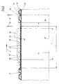
- a tab 5 is articulated by means of a Anlenkbolzens 6, which is also attached by means of such a Anlenkbolzens 6 at the appropriate location of the subsequent half-mold 2 and 2'.
- the chains 3, 3 'formed in this way are guided on their rearward end, seen in the direction of production 4, via guide wheels serving as so-called inlet rollers 7.
- the individual half-molds 2, 2 ' are pivoted in the circulation of the chains 3, 3' according to the direction of rotation arrows 8 and 8 'in a mold section 9, in each of which two half-molds 2, 2' are combined to form a mold pair, again in the production direction 4th successive mold pairs are close together.
- so-called closing rollers 10 are provided, which in the production direction 4 rear ends of the half-molds 2, 2 'merge accelerated.
- the inlet rollers 7 are rotatably mounted about axle journal 13 on the machine table 1.
- return rollers 14 are rotatably mounted about journals 15 around which the chains 3 and 3 'deflected and returned to the inlet rollers 7.
- the guide rails 12 end with guide rollers 11 already by the length of several half-molds 2 and 2 'in front of the return rollers 14, so that the half-molds 2 and 2' again moved away from each other and transverse to the production direction 4 from each other can be before they are pivoted by the return rollers 14.
- a toothing 16 is formed, wherein the two teeth 16 of the paired half-molds 2, 2' are aligned, so that from above a common drive pinion 17 can engage in this toothing 16, which the half-molds 2, 2 'in the forming section 9 as a closed mold by the forming section 9 pushes.
- the drive of this drive pinion 17 is effected in the usual manner by a motor, not shown, via a drive gear 18, which is fixed in a rotationally fixed manner on a shaft 19, which in turn carries the drive pinion 17.
- the shaft 19 is mounted in a bearing block 20 which is supported by spacer prisms 21 relative to the machine table and fixedly connected to the latter by means of screws 22.
- the tubes 23 will be described in more detail below.
- an extruder is provided, of which only the injection head 25, which will be described in more detail below, is indicated.
- the device described so far is known, for example from EP-A 0 065 729 (corresponding to US Pat. No. 4,492,551) and from DE 40 21 564 A1.
- a nozzle body 27 projecting into the molding section 9 is mounted on the spray head 25, in which an outer channel 28 and a Inner channel 29 are formed.
- the outer channel 28 terminates in an outer nozzle 30, the inner channel 29 terminates in an inner nozzle 31.
- the width a of the outer nozzle 30 and the width b of the inner nozzle 31 is in each case adjustable by a the respective nozzle 30 or 31 on the outside limiting nozzle ring 32 is adjustable by means of a nozzle ring nut 33 in the direction of the axis 26 and the production direction 4.
- the nozzle ring nut 33 is adjustable in each case on a corresponding thread 34 on the nozzle body 27.
- the nozzle body 27 is followed in the direction of production 4 by a calibration and tempering bell 35.
- This is provided with a likewise concentric with the axis 26 arranged in a conventional manner, provided substantially cylindrical Kalibrierzylinder 36 which is arranged on a tempering cylinder 37.
- a tempering channel 38 is formed, through which a tempering, so a cooling medium or a heating medium, can be passed.
- annular Formaus Principleung 39 is formed, which are connected in a known manner to partial-vacuum channels 40.
- the half-molds 2, 2 ' are formed so that in each case at predetermined intervals within the endlessly produced composite pipe 23 so-called spigot ends 46 are formed.
- a substantially cylindrical spigot recess 47 is formed in a pair of Halbkobllen 2, 2 ', which thus has a substantially cylindrical wall 48.
- a spigot 46 does not have to extend over the full length of a pair of half-shells 2, 2 'in the direction of production 4; it can also extend over only a part of this length.
- the diameter D of the cylindrical wall 48 is thus greater than the diameter d of the calibration cylinder 36 by twice the wall thickness c of the spigot end 46 to be produced.
- outer tube 41 and inner tube 43 takes place here only by the compression of the two tubes 41, 43 between the Kalibrierzylinder 36 and the wall 48 of the spigot recess 47.
- the speed of the mold can in this case by appropriate control of the drive motor for the Drive pinion 17 may have been withdrawn, so that more melt per unit length of the tube to be generated 23 passes into the spigot 46 than to produce the grooves 24 provided with composite pipe 23 so that the wall thickness c of the spigot end 46 is greater than the sum of the wall thicknesses e and f of outer tube 42 and inner tube 45.
- the compensation chambers may also extend parallel to the axis 26, but otherwise be the same size and connected to the partial vacuum channels.
- the compensation chambers 49 cause small circumferential web-like projections 53 to be formed on the outer wall 52 of a spigot end 46, the dimensions of which correspond at most to those of the compensation chamber 49.
- the width of the vacuum slots 50 is so small that melt can not get into it.
- the projections 53 become larger and wider in the opposite direction of the production direction 4. This is due to the fact that not all of the excess melt is pressed from the outset exclusively in the compensation chambers 49, but also partially backflows counter to the production direction 4, so that with increasing formation of a spigot, the relative melt abundance increases, with the result that more melt is pressed into the compensation chambers 49 and evades.
- a transition section 54 is further shown, the - in relation to the production direction 4 - front, i. is formed at the transition from provided with grooves 24 composite tube 23 to the spigot 46.
- This transition section 54 is separated out by means of two saw cuts 55, 56.
- a short pipe section formed by the transition section 54 is stepped out.
- a sleeve 57 is shown in phantom, which is formed by Aufmuffen the spigot end 46 - after separation of the transition portion 54. She also wears the projections 53 on its outside.
- the sleeve 57 is provided with a strong internal groove 58 for receiving a sealing ring.
- the inner diameter D 'of the cylindrical inner wall 59 of the sleeve 57 is approximately equal to or slightly greater than the outer diameter d' of the tube 23 with the grooves 24.
- the axial length I of the sleeve 57 through the Aufmuffen and in particular the formation of the inner groove 58 is less than the axial length L 'of the spigot end 46.
- Fig. 4 shows a connection of two tubes 23 with each other, in which the molded sleeve 57 is made in the manner described for Fig. 3 and width, ie the sleeve 57 via the grooved 24, provided with corrugated outer tube 42 and smooth inner tube 45 existing pipe 23 is pushed.
- a seal 60 is inserted in a groove 24, a seal 60 is inserted.
- Fig. 5 shows a composite pipe 23 with a sleeve 57 produced in the manner described, which is pushed onto a smooth-walled solid wall tube 61 or a pipe section in the form of a solid wall pipe.
- a seal 62 is arranged in the inner groove 58, which bears sealingly against the smooth cylindrical outer wall 63 of the solid wall tube 61.
Landscapes
- Engineering & Computer Science (AREA)
- Mechanical Engineering (AREA)
- Manufacturing & Machinery (AREA)
- Architecture (AREA)
- Civil Engineering (AREA)
- Structural Engineering (AREA)
- Extrusion Moulding Of Plastics Or The Like (AREA)
- Rigid Pipes And Flexible Pipes (AREA)
Claims (8)
- Procédé pour la fabrication continue d'un tube composite (23) en matière plastique, comprenant un tube intérieur lisse (45) de diamètre intérieur constant de bout en bout, et un tube extérieur (42) soudé audit tube intérieur et muni de rainures transversales (24) présentant des creusures (44), comportant une extrémité pointue (46) à paroi extérieurement lisse pour l'essentiel, et dont le diamètre extérieur est plus petit que le diamètre extérieur des rainures transversales (24), procédé dans lequel- un flexible extérieur (41) est extrudé,- le flexible extérieur (41) est muni, sous l'effet d'un vide partiel appliqué de l'extérieur, d'une ondulation à rainures transversales (24) présentant des creusures (44),- un flexible intérieur (43) est extrudé dans le flexible extérieur (41),- le flexible intérieur (43) est pressé contre les creusures (44) du flexible extérieur (41), et est soudé audit flexible extérieur (41) à cet emplacement,- le flexible extérieur (41) est amené, par intervalles préétablis, à la forme d'une extrémité pointue (46) sensiblement cylindrique, à paroi essentiellement lisse, et- le flexible intérieur (43) est pressé de l'intérieur contre le flexible extérieur (41), par toute sa superficie,caractérisé par le fait- que le flexible extérieur (41) est amené de l'extérieur, par application d'un vide partiel, à la forme de l'extrémité pointue (46) ;- et que la pression exercée sur la paroi extérieure (52) du flexible extérieur (41) est relâchée dans de petites zones superficielles, dans la région de l'extrémité pointue (46), ce qui donne naissance, à cet emplacement, à de petites protubérances (53) assurant la compensation d'un dosage imprécis lors de l'extrusion de la matière plastique.
- Procédé selon la revendication 1, caractérisé par le fait que la pression exercée sur la paroi extérieure (52) est relâchée dans des zones annulaires.
- Procédé selon la revendication 1 ou 2, caractérisé par le fait que la pression exercée sur les petites zones superficielles est relâchée par un vide partiel.
- Dispositif pour la mise en oeuvre du procédé selon l'une des revendications 1 à 3, dans lequel- des demi-coquilles (2, 2'), pourvues de cavités annulaires de moulage (39) et se complétant par paires respectives, sur un trajet de moulage (9), pour former un moule à axe médian longitudinal (26), sont agencées en révolution sur un plateau (1) de machine, avec guidage dans une direction de production (4),- les cavités de moulage (39) sont raccordées à des canaux (40) à vide partiel, ménagés dans les demi-coquilles (2, 2'),- une tête d'injection (25) d'une extrudeuse est disposée en amont du trajet de moulage (9),- la tête d'injection (25) est équipée d'une buse extérieure (30) en vue de l'extrusion d'un flexible extérieur (41); d'une buse intérieure (31), en aval dans la direction de production (4), en vue de l'extrusion d'un flexible intérieur (43); et, à son extrémité située à l'arrière dans la direction de production (4), d'une cloche (35) de calibrage et d'équilibrage thermique, dotée d'un cylindre de calibrage (36), et- au moins une paire de demi-coquilles (2, 2') est munie d'un évidement (47) affecté à une extrémité pointue, présentant une paroi (48) pour l'essentiel cylindrique,caractérisé par le fait que des chambres de compensation (49) sont ménagées dans la paroi (48) essentiellement cylindrique pour la formation de protubérances, dont les dimensions correspondent au maximum à ceux des chambres de compensations (49).
- Dispositif selon la revendication 4, caractérisé par le fait que les chambres de compensation (49) sont réalisées sous la forme d'anneaux agencés concentriquement à l'axe médian longitudinal (26).
- Dispositif selon la revendication 4 ou 5, caractérisé par le fait que les chambres de compensation (49) sont raccordées à des canaux (40) à vide partiel.
- Dispositif selon la revendication 6, caractérisé par le fait que les chambres de compensation (49) sont raccordées, par l'intermédiaire de fentes de dépression (50), à des canaux (40) à vide partiel.
- Dispositif selon la revendication 7, caractérisé par le fait que la largeur (h) des chambres de compensation (49), comparativement à la largeur (i) des fentes de dépression (50), obéit respectivement à la relation h ≤ 2i dans la direction de production (4).
Applications Claiming Priority (2)
| Application Number | Priority Date | Filing Date | Title |
|---|---|---|---|
| DE4240268A DE4240268A1 (de) | 1992-12-01 | 1992-12-01 | Verfahren und Vorrichtung zur fortlaufenden Herstellung eines Verbundrohres mit einem außen im wesentlichen glatten Abschnitt |
| DE4240268 | 1992-12-01 |
Publications (3)
| Publication Number | Publication Date |
|---|---|
| EP0600214A1 EP0600214A1 (fr) | 1994-06-08 |
| EP0600214B1 EP0600214B1 (fr) | 1998-03-04 |
| EP0600214B2 true EP0600214B2 (fr) | 2006-04-19 |
Family
ID=6474029
Family Applications (1)
| Application Number | Title | Priority Date | Filing Date |
|---|---|---|---|
| EP93117224A Expired - Lifetime EP0600214B2 (fr) | 1992-12-01 | 1993-10-25 | Procédé et dispositif pour la fabrication continue d'un tube composite comprenant une partie extérieuere essentiellement lisse |
Country Status (6)
| Country | Link |
|---|---|
| US (1) | US5472659A (fr) |
| EP (1) | EP0600214B2 (fr) |
| CN (1) | CN1042712C (fr) |
| CA (1) | CA2110360C (fr) |
| DE (2) | DE4240268A1 (fr) |
| ES (1) | ES2112943T3 (fr) |
Cited By (8)
| Publication number | Priority date | Publication date | Assignee | Title |
|---|---|---|---|---|
| US7484535B2 (en) | 2005-03-14 | 2009-02-03 | Advanced Drainage Systems, Inc. | Corrugated pipe with outer layer |
| US7980841B2 (en) | 2007-02-26 | 2011-07-19 | Advanced Drainage Systems, Inc. | Defined ratio dual-wall pipe die |
| US7988438B2 (en) | 2008-02-11 | 2011-08-02 | Advanced Drainage Systems, Inc. | Extrusion die vacuum seals |
| US8114324B2 (en) | 2008-10-14 | 2012-02-14 | Advanced Drainage Systems, Inc. | Apparatus and method for pressing an outer wall of pipe |
| US8496460B2 (en) | 2007-02-26 | 2013-07-30 | Advanced Drainage Systems, Inc. | Pipe extrusion die flow path apparatus and method |
| US8550807B2 (en) | 2008-05-28 | 2013-10-08 | Advanced Drainage Systems, Inc. | In-mold punch apparatus and methods |
| US8733405B2 (en) | 2005-03-14 | 2014-05-27 | Advanced Drainage Systems, Inc. | Corrugated pipe with outer layer |
| US8820800B2 (en) | 2007-11-16 | 2014-09-02 | Advanced Drainage Systems, Inc. | Multi-wall corrugated pipe couplings and methods |
Families Citing this family (14)
| Publication number | Priority date | Publication date | Assignee | Title |
|---|---|---|---|---|
| DE19504501A1 (de) * | 1995-02-13 | 1996-08-14 | Wilhelm Hegler | Verfahren und Anlage zur Herstellung eines Mehrschicht-Rohres aus thermoplastischem Kunststoff, insbesondere Polyolefin |
| DE19604311A1 (de) * | 1996-02-07 | 1997-08-14 | Ralph Peter Dr Ing Hegler | Verbundrohr mit Muffe und Verfahren zu seiner Herstellung |
| DE19640928A1 (de) * | 1996-10-04 | 1998-04-09 | Ralph Peter Dr Ing Hegler | Vorrichtung zur Herstellung von Kunststoff-Verbund-Rohren |
| IT1290468B1 (it) * | 1997-03-21 | 1998-12-04 | Giancarlo Tamborini | Struttura di tubo di scarico a realizzazione semplificata particolarmente studiata per elettrodomestici e simili |
| DE19724113A1 (de) * | 1997-06-09 | 1998-12-10 | Ralph Peter Dr Hegler | Verbundrohr mit angeformter Rohr-Muffe und Verfahren zu dessen Herstellung |
| DE19848470A1 (de) * | 1998-10-21 | 2000-04-27 | Ralph Peter Hegler | Verfahren zur fortlaufenden Herstellung eines Verbundrohres mit einer Rohr-Muffe und Vorrichtung zur Durchführung des Verfahrens |
| US6199592B1 (en) * | 1999-02-05 | 2001-03-13 | Hancor, Inc. | Pipe structure and method of manufacture |
| EP1317334B1 (fr) * | 2000-09-11 | 2005-06-08 | Manfred Arno Alfred Lupke | Appareil de fabrication de tuyaux regulant le volume de plastique le long de la paroi d'un tuyau |
| US6752955B2 (en) | 2001-07-13 | 2004-06-22 | Trw Inc. | Method of manufacturing a boot seal |
| DK1612030T3 (da) * | 2004-07-03 | 2008-01-21 | Ralph-Peter Dr-Ing Hegler | Fremgangsmåde til kontinuerlig fremstilling af et dobbeltvægget korrugeret rör med rörmuffe, det dobbeltvæggede korrugerede rör samt et apparat til udövelse af fremgangsmåden |
| EP1916087A1 (fr) * | 2006-10-26 | 2008-04-30 | Drossbach GmbH & Co. KG | Dispositif destiné à l'application de matière synthétique sur une pièce à usiner |
| PT2008139004W (pt) * | 2007-05-14 | 2010-06-15 | Uralita Sist S De Tuberias S A | Método para o fabrico de um tubo corrugado de parede tripla, cabeça utilizada no seu fabrico e tubo assim obtido |
| US8820801B2 (en) | 2007-11-16 | 2014-09-02 | Advanced Drainage System, Inc. | Multi-wall corrugated pipe couplings and methods |
| EP2323833A1 (fr) * | 2008-08-06 | 2011-05-25 | Jain Irrigation Systems Limited | Nouveau tuyau avec des embouts intégrés mâle et femelle, nouveau raccord l'utilisant, et procédés pour fabriquer le tuyau et le raccord |
Family Cites Families (7)
| Publication number | Priority date | Publication date | Assignee | Title |
|---|---|---|---|---|
| JPS6036143A (ja) * | 1983-08-08 | 1985-02-25 | Takiron Co Ltd | 継手部を有した二重壁パイプの製造方法 |
| JPS61148035A (ja) * | 1984-12-21 | 1986-07-05 | Takiron Co Ltd | 二重壁管の製造法 |
| JPS61293821A (ja) * | 1985-06-21 | 1986-12-24 | Takiron Co Ltd | コルゲ−ト管のスリ−ブの成形方法 |
| FI77405C (fi) * | 1986-03-20 | 1989-03-10 | Uponor Nv | Foerfarande och anordning foer framstaellning av kamflaensroer. |
| DE3701822A1 (de) * | 1987-01-22 | 1988-08-11 | Uponor Nv | Verfahren und anordnung zum strangpressen von kunststoffrohren |
| NL8701164A (nl) * | 1987-05-14 | 1988-12-01 | Wavin Bv | Kunststofbuis met aan het buitenoppervlak massieve dwarsribben, inrichting voor toepassing in een installatie voor het vormen van dergelijke buizen; installatie voor het vormen van buizen die een dergelijke inrichting omvat en werkwijze voor het vormen van een kunststofbuis onder toepassing van een dergelijke installatie. |
| DE4210482A1 (de) * | 1992-03-31 | 1993-10-07 | Wilhelm Hegler | Verfahren und Vorrichtung zur fortlaufenden Herstellung eines Verbundrohres mit Rohr-Muffe |
-
1992
- 1992-12-01 DE DE4240268A patent/DE4240268A1/de not_active Withdrawn
-
1993
- 1993-10-25 DE DE59308206T patent/DE59308206D1/de not_active Expired - Lifetime
- 1993-10-25 EP EP93117224A patent/EP0600214B2/fr not_active Expired - Lifetime
- 1993-10-25 ES ES93117224T patent/ES2112943T3/es not_active Expired - Lifetime
- 1993-11-19 US US08/154,855 patent/US5472659A/en not_active Expired - Fee Related
- 1993-11-30 CA CA002110360A patent/CA2110360C/fr not_active Expired - Fee Related
- 1993-11-30 CN CN93121112A patent/CN1042712C/zh not_active Expired - Fee Related
Cited By (8)
| Publication number | Priority date | Publication date | Assignee | Title |
|---|---|---|---|---|
| US7484535B2 (en) | 2005-03-14 | 2009-02-03 | Advanced Drainage Systems, Inc. | Corrugated pipe with outer layer |
| US8733405B2 (en) | 2005-03-14 | 2014-05-27 | Advanced Drainage Systems, Inc. | Corrugated pipe with outer layer |
| US7980841B2 (en) | 2007-02-26 | 2011-07-19 | Advanced Drainage Systems, Inc. | Defined ratio dual-wall pipe die |
| US8496460B2 (en) | 2007-02-26 | 2013-07-30 | Advanced Drainage Systems, Inc. | Pipe extrusion die flow path apparatus and method |
| US8820800B2 (en) | 2007-11-16 | 2014-09-02 | Advanced Drainage Systems, Inc. | Multi-wall corrugated pipe couplings and methods |
| US7988438B2 (en) | 2008-02-11 | 2011-08-02 | Advanced Drainage Systems, Inc. | Extrusion die vacuum seals |
| US8550807B2 (en) | 2008-05-28 | 2013-10-08 | Advanced Drainage Systems, Inc. | In-mold punch apparatus and methods |
| US8114324B2 (en) | 2008-10-14 | 2012-02-14 | Advanced Drainage Systems, Inc. | Apparatus and method for pressing an outer wall of pipe |
Also Published As
| Publication number | Publication date |
|---|---|
| DE4240268A1 (de) | 1994-06-09 |
| DE59308206D1 (de) | 1998-04-09 |
| EP0600214B1 (fr) | 1998-03-04 |
| CN1096480A (zh) | 1994-12-21 |
| CA2110360A1 (fr) | 1994-06-02 |
| CN1042712C (zh) | 1999-03-31 |
| CA2110360C (fr) | 2005-01-25 |
| US5472659A (en) | 1995-12-05 |
| EP0600214A1 (fr) | 1994-06-08 |
| ES2112943T3 (es) | 1998-04-16 |
Similar Documents
| Publication | Publication Date | Title |
|---|---|---|
| EP0600214B2 (fr) | Procédé et dispositif pour la fabrication continue d'un tube composite comprenant une partie extérieuere essentiellement lisse | |
| EP0789176B1 (fr) | Tube composite avec manchon et procédé pour sa fabrication | |
| EP0890770B1 (fr) | Tube composite avec manchon intégrée et méthode pour sa fabrication | |
| EP0301189B1 (fr) | Procédé et dispositif de fabrication d'un tube nervuré en matière plastique | |
| DE4210482A1 (de) | Verfahren und Vorrichtung zur fortlaufenden Herstellung eines Verbundrohres mit Rohr-Muffe | |
| DE1704718A1 (de) | Verfahren und Vorrichtung zur Herstellung von Kunststoffrohren mit ring- oder schraubenlinienfoermig gerillter Aussenwand | |
| EP0834386B1 (fr) | Dispositif de fabrication d'un tuyau plastique à double paroi | |
| DE2403618B2 (de) | Vorrichtung zum Herstellen eines doppelwandigen Kunststoffrohres | |
| EP2452803B1 (fr) | Dispositif pour la fabrication des tubes thermoplastiques ondulées | |
| EP2065159A1 (fr) | Dispositif de fabrication continue d'un tuyau composite doté d'un manchon tubulaire | |
| EP0580984B1 (fr) | Dispositif pour la fabrication d'un tuyau à parois ondulées | |
| EP0464411B1 (fr) | Dispositif pour la production de tuyaux en matière plastique | |
| DE2104294A1 (fr) | ||
| EP1911565A2 (fr) | Dispositif destiné à la fabrication de conduites composites | |
| DE19941160A1 (de) | Zylinder für einen Schneckenextruder mit Kanälen für ein Temperiermedium | |
| EP0855263A2 (fr) | Procédé et appareil pour la production d'un tuyau de gainage ondulé entourant un conduit pour le transport de fluide | |
| DE69415920T2 (de) | Verfahren und eine Form zum Herstellen einer Ausdehnung, wie z.b. einer Hülse, in einem Rohr und ein Kunststoffrohr | |
| DE102009035040B4 (de) | Verfahren zur fortlaufenden Herstellung eines Rohres und Vorrichtung zur Durchführung des Verfahrens | |
| EP3153296B1 (fr) | Tête d'extrusion pour un dispositif de fabrication d'un tuyau composite | |
| DE3426680C2 (fr) | ||
| DE3235146C2 (de) | Anschluß eines flexiblen Schlauches an ein Rohr und Verfahren zur Herstellung eines Anschlußrohrendes für den Anschluß eines Schlauches | |
| DE9321573U1 (de) | Vorrichtung zur fortlaufenden Herstellung eines Verbundrohres mit Rohr-Muffe | |
| EP2436504A2 (fr) | Procédé de fabrication continue d'un tuyau composite doté d'un manchon tubulaire, tuyau composite doté d'un manchon tubulaire et dispositif d'exécution du procédé et de fabrication du tuyau composite | |
| DE2213561A1 (de) | Verfahren und vorrichtung zum anformen einer muffe mit darin umlaufender sicke an das ende eines rohres aus thermoplastischem kunststoff | |
| EP1239999B1 (fr) | Procede et appareil permettant de modifier la forme d'un tuyau en plusieurs etapes |
Legal Events
| Date | Code | Title | Description |
|---|---|---|---|
| PUAI | Public reference made under article 153(3) epc to a published international application that has entered the european phase |
Free format text: ORIGINAL CODE: 0009012 |
|
| AK | Designated contracting states |
Kind code of ref document: A1 Designated state(s): DE ES FR GB IT SE |
|
| 17P | Request for examination filed |
Effective date: 19940511 |
|
| 17Q | First examination report despatched |
Effective date: 19950905 |
|
| GRAG | Despatch of communication of intention to grant |
Free format text: ORIGINAL CODE: EPIDOS AGRA |
|
| GRAG | Despatch of communication of intention to grant |
Free format text: ORIGINAL CODE: EPIDOS AGRA |
|
| GRAH | Despatch of communication of intention to grant a patent |
Free format text: ORIGINAL CODE: EPIDOS IGRA |
|
| GRAH | Despatch of communication of intention to grant a patent |
Free format text: ORIGINAL CODE: EPIDOS IGRA |
|
| GRAA | (expected) grant |
Free format text: ORIGINAL CODE: 0009210 |
|
| AK | Designated contracting states |
Kind code of ref document: B1 Designated state(s): DE ES FR GB IT SE |
|
| GBT | Gb: translation of ep patent filed (gb section 77(6)(a)/1977) |
Effective date: 19980305 |
|
| REF | Corresponds to: |
Ref document number: 59308206 Country of ref document: DE Date of ref document: 19980409 |
|
| REG | Reference to a national code |
Ref country code: ES Ref legal event code: FG2A Ref document number: 2112943 Country of ref document: ES Kind code of ref document: T3 |
|
| ITF | It: translation for a ep patent filed | ||
| ET | Fr: translation filed | ||
| PG25 | Lapsed in a contracting state [announced via postgrant information from national office to epo] |
Ref country code: SE Free format text: LAPSE BECAUSE OF FAILURE TO SUBMIT A TRANSLATION OF THE DESCRIPTION OR TO PAY THE FEE WITHIN THE PRESCRIBED TIME-LIMIT Effective date: 19980604 |
|
| PLBQ | Unpublished change to opponent data |
Free format text: ORIGINAL CODE: EPIDOS OPPO |
|
| PLBI | Opposition filed |
Free format text: ORIGINAL CODE: 0009260 |
|
| PLBF | Reply of patent proprietor to notice(s) of opposition |
Free format text: ORIGINAL CODE: EPIDOS OBSO |
|
| 26 | Opposition filed |
Opponent name: CORMA INC. Effective date: 19981203 |
|
| PLBF | Reply of patent proprietor to notice(s) of opposition |
Free format text: ORIGINAL CODE: EPIDOS OBSO |
|
| PLBF | Reply of patent proprietor to notice(s) of opposition |
Free format text: ORIGINAL CODE: EPIDOS OBSO |
|
| PLBF | Reply of patent proprietor to notice(s) of opposition |
Free format text: ORIGINAL CODE: EPIDOS OBSO |
|
| RAP2 | Party data changed (patent owner data changed or rights of a patent transferred) |
Owner name: HEGLER, RALPH PETER, DR.-ING. |
|
| REG | Reference to a national code |
Ref country code: GB Ref legal event code: IF02 |
|
| PLBO | Opposition rejected |
Free format text: ORIGINAL CODE: EPIDOS REJO |
|
| PLBO | Opposition rejected |
Free format text: ORIGINAL CODE: EPIDOS REJO |
|
| PLAW | Interlocutory decision in opposition |
Free format text: ORIGINAL CODE: EPIDOS IDOP |
|
| APAC | Appeal dossier modified |
Free format text: ORIGINAL CODE: EPIDOS NOAPO |
|
| APAC | Appeal dossier modified |
Free format text: ORIGINAL CODE: EPIDOS NOAPO |
|
| PLBQ | Unpublished change to opponent data |
Free format text: ORIGINAL CODE: EPIDOS OPPO |
|
| PLAB | Opposition data, opponent's data or that of the opponent's representative modified |
Free format text: ORIGINAL CODE: 0009299OPPO |
|
| R26 | Opposition filed (corrected) |
Opponent name: CORMA INC. Effective date: 19981203 |
|
| REG | Reference to a national code |
Ref country code: GB Ref legal event code: 732E |
|
| PGFP | Annual fee paid to national office [announced via postgrant information from national office to epo] |
Ref country code: ES Payment date: 20041026 Year of fee payment: 12 |
|
| APAA | Appeal reference recorded |
Free format text: ORIGINAL CODE: EPIDOS REFN |
|
| APBU | Appeal procedure closed |
Free format text: ORIGINAL CODE: EPIDOSNNOA9O |
|
| APAH | Appeal reference modified |
Free format text: ORIGINAL CODE: EPIDOSCREFNO |
|
| PG25 | Lapsed in a contracting state [announced via postgrant information from national office to epo] |
Ref country code: IT Free format text: LAPSE BECAUSE OF NON-PAYMENT OF DUE FEES Effective date: 20051025 |
|
| PUAH | Patent maintained in amended form |
Free format text: ORIGINAL CODE: 0009272 |
|
| STAA | Information on the status of an ep patent application or granted ep patent |
Free format text: STATUS: PATENT MAINTAINED AS AMENDED |
|
| 27A | Patent maintained in amended form |
Effective date: 20060419 |
|
| AK | Designated contracting states |
Kind code of ref document: B2 Designated state(s): DE ES FR GB IT SE |
|
| GBTA | Gb: translation of amended ep patent filed (gb section 77(6)(b)/1977) | ||
| PG25 | Lapsed in a contracting state [announced via postgrant information from national office to epo] |
Ref country code: ES Free format text: LAPSE BECAUSE OF FAILURE TO SUBMIT A TRANSLATION OF THE DESCRIPTION OR TO PAY THE FEE WITHIN THE PRESCRIBED TIME-LIMIT Effective date: 20060730 |
|
| PGFP | Annual fee paid to national office [announced via postgrant information from national office to epo] |
Ref country code: DE Payment date: 20061129 Year of fee payment: 14 |
|
| ET3 | Fr: translation filed ** decision concerning opposition | ||
| PG25 | Lapsed in a contracting state [announced via postgrant information from national office to epo] |
Ref country code: DE Free format text: LAPSE BECAUSE OF THE APPLICANT RENOUNCES Effective date: 20070723 |
|
| REG | Reference to a national code |
Ref country code: FR Ref legal event code: ST Effective date: 20080630 |
|
| PGFP | Annual fee paid to national office [announced via postgrant information from national office to epo] |
Ref country code: FR Payment date: 20061020 Year of fee payment: 14 |
|
| PG25 | Lapsed in a contracting state [announced via postgrant information from national office to epo] |
Ref country code: FR Free format text: LAPSE BECAUSE OF NON-PAYMENT OF DUE FEES Effective date: 20071031 |
|
| PGFP | Annual fee paid to national office [announced via postgrant information from national office to epo] |
Ref country code: GB Payment date: 20081024 Year of fee payment: 16 |
|
| PG25 | Lapsed in a contracting state [announced via postgrant information from national office to epo] |
Ref country code: GB Free format text: LAPSE BECAUSE OF NON-PAYMENT OF DUE FEES Effective date: 20091025 |