EP0600300A2 - Vergnügungsbahn - Google Patents
Vergnügungsbahn Download PDFInfo
- Publication number
- EP0600300A2 EP0600300A2 EP93118516A EP93118516A EP0600300A2 EP 0600300 A2 EP0600300 A2 EP 0600300A2 EP 93118516 A EP93118516 A EP 93118516A EP 93118516 A EP93118516 A EP 93118516A EP 0600300 A2 EP0600300 A2 EP 0600300A2
- Authority
- EP
- European Patent Office
- Prior art keywords
- passenger
- rails
- car
- retainer
- ride system
- Prior art date
- Legal status (The legal status is an assumption and is not a legal conclusion. Google has not performed a legal analysis and makes no representation as to the accuracy of the status listed.)
- Granted
Links
- 238000009987 spinning Methods 0.000 claims abstract description 50
- 230000007246 mechanism Effects 0.000 claims abstract description 23
- 230000013011 mating Effects 0.000 claims description 35
- 230000008878 coupling Effects 0.000 claims description 28
- 238000010168 coupling process Methods 0.000 claims description 28
- 238000005859 coupling reaction Methods 0.000 claims description 28
- 239000011295 pitch Substances 0.000 description 9
- 238000010276 construction Methods 0.000 description 5
- 230000035807 sensation Effects 0.000 description 5
- 230000005484 gravity Effects 0.000 description 4
- 238000005096 rolling process Methods 0.000 description 4
- 230000001012 protector Effects 0.000 description 3
- 210000001015 abdomen Anatomy 0.000 description 2
- 210000000481 breast Anatomy 0.000 description 2
- 239000002131 composite material Substances 0.000 description 2
- 239000011435 rock Substances 0.000 description 2
- 230000001174 ascending effect Effects 0.000 description 1
- 230000003190 augmentative effect Effects 0.000 description 1
- 230000008901 benefit Effects 0.000 description 1
- 230000006835 compression Effects 0.000 description 1
- 238000007906 compression Methods 0.000 description 1
- 230000006870 function Effects 0.000 description 1
- 230000006872 improvement Effects 0.000 description 1
- 238000003754 machining Methods 0.000 description 1
- 238000004519 manufacturing process Methods 0.000 description 1
- 230000004048 modification Effects 0.000 description 1
- 238000012986 modification Methods 0.000 description 1
- 230000004044 response Effects 0.000 description 1
- 230000000717 retained effect Effects 0.000 description 1
- 238000004088 simulation Methods 0.000 description 1
Images



Classifications
-
- B—PERFORMING OPERATIONS; TRANSPORTING
- B60—VEHICLES IN GENERAL
- B60R—VEHICLES, VEHICLE FITTINGS, OR VEHICLE PARTS, NOT OTHERWISE PROVIDED FOR
- B60R21/00—Arrangements or fittings on vehicles for protecting or preventing injuries to occupants or pedestrians in case of accidents or other traffic risks
- B60R21/02—Occupant safety arrangements or fittings, e.g. crash pads
-
- A—HUMAN NECESSITIES
- A63—SPORTS; GAMES; AMUSEMENTS
- A63G—MERRY-GO-ROUNDS; SWINGS; ROCKING-HORSES; CHUTES; SWITCHBACKS; SIMILAR DEVICES FOR PUBLIC AMUSEMENT
- A63G7/00—Up-and-down hill tracks; Switchbacks
-
- B—PERFORMING OPERATIONS; TRANSPORTING
- B60—VEHICLES IN GENERAL
- B60R—VEHICLES, VEHICLE FITTINGS, OR VEHICLE PARTS, NOT OTHERWISE PROVIDED FOR
- B60R21/00—Arrangements or fittings on vehicles for protecting or preventing injuries to occupants or pedestrians in case of accidents or other traffic risks
- B60R2021/003—Arrangements or fittings on vehicles for protecting or preventing injuries to occupants or pedestrians in case of accidents or other traffic risks characterised by occupant or pedestian
- B60R2021/0039—Body parts of the occupant or pedestrian affected by the accident
- B60R2021/0058—Shoulders
-
- B—PERFORMING OPERATIONS; TRANSPORTING
- B60—VEHICLES IN GENERAL
- B60R—VEHICLES, VEHICLE FITTINGS, OR VEHICLE PARTS, NOT OTHERWISE PROVIDED FOR
- B60R21/00—Arrangements or fittings on vehicles for protecting or preventing injuries to occupants or pedestrians in case of accidents or other traffic risks
- B60R2021/0065—Type of vehicles
- B60R2021/0097—Amusement vehicles
-
- B—PERFORMING OPERATIONS; TRANSPORTING
- B60—VEHICLES IN GENERAL
- B60R—VEHICLES, VEHICLE FITTINGS, OR VEHICLE PARTS, NOT OTHERWISE PROVIDED FOR
- B60R21/00—Arrangements or fittings on vehicles for protecting or preventing injuries to occupants or pedestrians in case of accidents or other traffic risks
- B60R21/02—Occupant safety arrangements or fittings, e.g. crash pads
- B60R2021/0206—Self-supporting restraint systems, e.g. restraining arms, plates or the like
- B60R2021/022—Self-supporting restraint systems, e.g. restraining arms, plates or the like mounted on seats
Definitions
- the present invention relates to amusement track ride systems, such as roller coasters, loop coasters, twist coasters, etc., which comprise a track formed of a pair of rails and a car traveling along the track, and are located in amusement parks and the like.
- amusement track ride systems such as roller coasters, loop coasters, twist coasters, etc., which comprise a track formed of a pair of rails and a car traveling along the track, and are located in amusement parks and the like.
- a loop coaster is known as an example of an amusement track ride system in an amusement park or the like.
- a track is formed of a pair of rails on which a car can travel.
- a loop section is formed in the middle of the track such that the car is subjected to a force for looping as it passes through the loop section.
- the loop coaster of this type can provide the fun of a ground simulation of stunt flying of an airplane, however, the simple looping is just a monotonous sport.
- the track is provided with a partial spinning section.
- the spinning section is twisted around a middle line between a pair of rails which are formed of a pipe member each.
- the rails are supported by means of a number of hoops, which are coaxially arranged side by side in the traveling direction of the car.
- the hoops are coupled together at predetermined distances from one another by means of a plurality of support beams, which are arranged at regular intervals in the circumferential direction of the hoops.
- the hoops and the support beams constitute a tunnel-shaped structure or imaginary cylinder which extends in the traveling direction of the car.
- the paired rails are fixed to each hoop at an angular distance of about 180° from each other, in the circumferential direction, so that the middle line between the twisted rails is substantially in alignment with the center line of the imaginary cylinder.
- the center line of each twisted rail is in alignment with the center line of the imaginary cylinder.
- the car traveling along the paired rails is situated between the rails, and is connected thereto by means of wheels on either side of the car. In this arrangement, the car travels along the center line of the imaginary cylinder while spinning along the wall of the cylinder.
- the car has a chassis which extends in the traveling direction, and a plurality of passenger seats are arranged in front and in rear on the chassis.
- a ring-shaped front frame is provided on the front portion of the chassis, and a plurality of front wheels are rotatably mounted on each lateral side of the front frame.
- a rear support is provided on the rear portion of the chassis, and a cross frame, which extends in a direction perpendicular to the transverse direction, is attached to the rear support for vertical rocking motion by means of a support shaft (longitudinal bogie shaft).
- a plurality of rear wheels are rotatably mounted on each lateral side of the cross frame.
- the front and rear wheels are individually in rolling contact with the topside, underside, and inside of each rail, and hug the rails lest derailment be caused.
- the car travels along the rails as the wheels rotate. Since the rails are spun in a helix, the car runs straight in a spin. In this case, the center of spinning of the car is set so as to be substantially in alignment with the middle line between the paired rails or the center line of the imaginary cylinder.
- the car runs straight in a spin as it passes through the spinning section, so that passengers can enjoy spinning which is more varied than conventional looping.
- the car is situated between the paired rails arranged at an angular distance of 180°C from each other in the circumferential direction, and the center of its spinning is substantially in alignment with the middle line between the rails or the center line of the imaginary cylinder. Accordingly, the elevation of the seats is relatively low as compared with the rails, and the eye level of the passengers is close to the height of the rails on either side. Inevitably, therefore, the passengers' view is narrowed by the rails.
- the rails are situated near the passengers' eye level, moreover, the front and rear wheels are also situated close to the eye level, thereby narrowing the field of vision of the passengers. Moreover, the passengers will be frightened at the wheels rotating beside their faces at high speed.
- Use of a safety protector or cover to conceal the wheels entails an increase of essential components in number, and therefore, a complicated construction.
- the aforementioned ride system such as a twist coaster or loop coaster, requires use of means for holding the body of each passenger in the car, in order to prevent the passenger from being thrown off the car by centrifugal force or gravity.
- a body holding apparatus in Jpn. Pat. Appln. KOKAI Publication No. 51-100531.
- This holding apparatus comprises a U-shaped arm, which is rockably mounted on the back rest of each seat of a car running along a looped or twisted course, and covers and holds down the upper part of the passenger's body, including the shoulders and the belly.
- the rocking arm of this type has a fixed rocking center around which it is rocked downward, however, it sometimes cannot satisfactorily hold down the passenger's body, depending on the body dimensions. If the passenger is too small in stature or sitting height, there is a possibility of a gap being formed between the shoulders and the proximal end portion of the vertical-type rocking arm near the rocking center. If the passenger's stature or sitting height is too great, in contrast with this, the arm engages the passenger's shoulders at its proximal end, and its rocking motion is checked. Thus, the distal end of the arm fails to reach the breast or belly, possibly lifting.
- the present invention has been contrived in consideration of these circumstances, and its object is to provide an amusement track ride system, in which cars can be made to travel spinning to afford good amusements, and each passenger's body can be securely held to ensure high safety without allowing rails, wheels, etc. to come into sight.
- a ride system comprises a pair of rails forming a track and a car traveling along the rails.
- the car includes a chassis, a passenger seat on the chassis, and a plurality of wheel portions on the chassis, situated close to the feet of a passenger in the passenger seat and engaging the rails.
- the track includes a spinning section such that the paired rails extend in a helix along the inner surface of an imaginary cylinder having a central axis at the spinning section.
- the diameter of the imaginary cylinder is set so that the axis of helical rotation of the car traveling in a spin along the rails passes through the car and is substantially in alignment with the central axis of the imaginary cylinder.
- the rails are arranged in a helix in the spinning section, so that the car runs straight in a spin as it passes through the spinning section.
- the paired rails are designed so as to form a helix along the inner surface of the imaginary cylinder, and so that the axis of helical rotation of the car spinning along the rails is substantially in alignment with the central axis of the imaginary cylinder. Accordingly, the rails are situated under the car and kept away from the passenger's eye level. Thus, the passenger can enjoy a wider field of vision cleared of the wheels. Further, the wheels need not be concealed by means of any special protector or the like.
- a car traveling along a pair of rails forming a track includes a chassis, a passenger seat on the chassis, and a holding device on the chassis for holding a passenger in the passenger seat.
- the holding device includes shoulder retainer attached to the seat back rest and used to hold down the shoulders of the passenger in the passenger seat from above, a guide mechanism in the passenger seat for guiding the shoulder retainer for movement in the extending direction of the seat back rest, locking means for locking the shoulder retainer to prevent the retainer from moving away from the passenger's shoulders when the retainer is guided by the guide mechanism to a position where the retainer abuts against the passenger's shoulders, unlocking means for unlocking the shoulder retainer locked by the locking means, and urging means for urging the shoulder retainer to move away from the passenger's shoulders.
- the shoulder retainer for holding down the passenger's shoulders from above is movable in the extending direction of the seat back rest or the vertical direction.
- the shoulders can be securely held down from above by moving the retainer.
- the passenger's body can be securely held in a safe manner. Since the shoulder retainer is movable in the vertical direction, moreover, no special space is needed with respect to the transverse direction of the seat.
- the locking means includes a rack, attached to the car and formed having a number of mating teeth arranged in the vertical direction, and a plurality of retaining pawls arranged in the vertical direction on the shoulder retainer and adapted to engage the mating teeth.
- the pitch of the retaining pawls is different from that of the mating teeth.
- one of the retaining pawls engages one of the mating teeth on the rack. If the engaged retaining pawl is disengaged or damaged, therefore, the other pawl engages the mating tooth, so that the shoulder retainer cannot be unlocked, thus ensuring high safety. Since the respective pitches of the mating teeth of the rack and the retaining pawls are different, one of the retaining pawls can engage its nearest mating tooth. Thus, the engagement pitch can be shortened.
- the rack of the locking means is formed of a rod member having the numerous mating teeth arranged in the axial direction on one side thereof with respect to the circumferential direction, and the unlocking means slidingly unlocks the engaging tooth from the retaining pawl by rocking the rack.
- the unlocking means has a simple construction, and can be operated with ease.
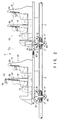
- FIGS. 1 to 11 show an amusement track ride system according to an embodiment of the present invention, in which:
- FIG. 1 schematically shows an outline of the ride system.
- the ride system comprises a pair of rails 2 and a train 3 of cars 10 traveling along the rails.
- a platform 70 is located beside the lowest portion of the track 1, and passengers get on and off the cars 10 at the platform 70.
- the train 3 advances to a hoisting section 71, where it is pulled up an upgrade by means of a chain (not shown).
- the train 3 is pulled up through the hoisting section 71 to a portion 72 corresponding to the highest point of the track 1, whereupon it is released from the chain.
- the train 3 enters a gentle downgrade, and then starts to be automatically run by gravity.
- a straight spinning section 73 (mentioned later) is formed in this downgrade.
- the train 3 falls straight in a spin.
- the train 3 After passing through the section 73, the train 3 enters a curved spinning section 74.
- the train 3 further spins as it travels along a curve, thus making a complex motion.
- the train 3 moves past a plurality of curves, and then returns to the platform 70 while reducing its speed.
- the track 1 is formed of the paired rails 2 which are supported by means of a number of supporting structures, such as supporting legs 75.
- each car 10 which travels along the rails 2, includes a substantially rectangular chassis 11 extending in the longitudinal direction or traveling direction.
- the chassis 11 carries thereon a plurality of seats 12 for the passengers.
- the seats 12 are arranged in a plurality of lines, in front and in rear, on the chassis 11. In each line, the seats are arranged side by side in the transverse direction of the chassis 11.
- Each seat 12 includes a seating face 13 and a seat back rest 14 extending upward from the seating face.
- wheel portions 80 which are in engagement with their corresponding rails 2, are arranged individually at the two corners on the front end side of the bottom of the chassis 11. More specifically, a rotatable support shaft (vertical bogie shaft) 81 extends vertically downward from the center of the front end portion of the chassis 11. A front cross frame 82 is attached to the extended end of the shaft 81 so as to extend at right angles to the rails 2. The wheel portions 80 are mounted individually on the right and left end portions of the frame 82. Thus, the wheel portions 80 can swing around the shaft 81, from side to side with respect to the advancing direction of the train 3.
- a rotatable support shaft vertical bogie shaft
- Each two adjacent cars 10 are coupled to each other by means of a ball joint 83 for use as coupling means, which is interposed between the respective centers of the rear end of the front car and the front end of the rear car.
- the ball joint 83 With use of the ball joint 83, the rear car 10 can swing freely in a desired direction with respect to the front car 10.
- the rearmost car (not shown) is provided with wheel portions which are arranged individually at the four corners of the underside of the chassis 11.
- Each wheel portion 80 includes a pair of tractor wheels 15 in rolling contact with the topside of its corresponding rail 2, an upstop wheel 16 in rolling contact with the underside of the rail, and a pair of guide wheels 17 in rolling contact with the outside of the rail.
- the wheel portion 80 hugs the rail from the topside, underside, and outside thereof lest derailment be caused.
- each car 10 travels along the rails. While the car 10 is running along the rails 2, the rails 2 are always situated on the bottom side of the car, that is, under the feet of the passengers in the seats 12.
- the straight spinning section 73 includes a number of hoops 76 to which the rails 2, formed of a pipe each, are fixed.
- the hoops 76 have the same diameter, and are arranged coaxially at regular intervals in the traveling direction of the train 3.
- the hoops 76 are coupled to one another by means of a plurality of support beams 77, e.g., four in number, which extend in the traveling direction of the train 3.
- the support beams 77 are arranged at regular intervals in the circumferential direction of the hoops 76.
- the hoops 76 and the beams 77 constitute a tunnel-shaped structure or imaginary cylinder 78 which extends in the traveling direction of the train 3.
- the structure 78 is in the form of a straight cylinder having a straight central axis O2, and slightly declines from the highest portion 72 of the track 1. This downgrade is designed so that the train 3 is subjected to a predetermined centrifugal force produced by its helical motion which accompanies the passage of the train 3 through the straight spinning section 73, which will be described later.
- the paired rails 2 helically extend along the inner surface of the imaginary cylinder 78, and are fixed to the individual hoops 76.
- the rails 2 look as if they stuck to the inner surface of the structure 78, and their central axis of the helical rotation is in alignment with the central axis O2 of the structure 78.
- An intermediate axis O1 which extends halfway between the rails 2, is a helical axis deviated from the central axis O2 of the structure 78.
- the lead angle of the helical rails 2 is set in consideration of the traveling speed of the train 3 lest the cars 10 be subjected to an excessive centrifugal force. Also, the lead angle is substantially fixed throughout the length of the spinning section 73.
- the train 3 on the rails 2 advances helically or in a spin along the inside of the imaginary cylinder 78.
- the inner diameter of the structure 78 that is, the diameter of a helix the rails 2 form, is set so that the central axis O2 is in alignment with the helical rotation axis O3 of the train 3, and more specifically, that the rotation axis O3 extends through the train 3 and is on the same level as the heads of the passengers in the seats 12 of each car 10.
- the intermediate axis O1 between the rails 2 is off the central axis O2 of the imaginary cylinder 78.
- the rotation axis O3 of the train 3 is set so that it is substantially in alignment with the central axis O2 of the imaginary cylinder 78 and passes through the passengers' heads. Even though the intermediate axis O1 between the rails 2 is helical, therefore, the cars 10 cannot be subjected to an excessive centrifugal force, so that the passengers can be protected against a great centrifugal force.
- the frame member 87 includes a first half portion constituting a quarter-round curve 84 with a curvature radius R1, a second half portion constituting a quarter-round curve 86 with a curvature radius R2, and a straight portion 85 connecting these curves 84 and 86.
- the rails 2 are spun in the section between the starting point of the first-half curve 84 and the end of the second-half curve 86 so that the train 3 makes one revolution in this section.
- the rails 2 is arranged along the inner surface of an imaginary cylinder 78b curved along the support frame 87 and having a constant diameter.
- a centrifugal force is produced as the train 3 travels along the curves.
- the train 3 is continually subjected to a centrifugal force associated with its speed and the curvature radius as it travels from the starting point of the first-half curve 84 to the end of the second-half curve 86.
- a centrifugal force is produced when the train 3 spins around the bent central axis (traveling central axis of the imaginary cylinder 78b) of the curves 84 and 86.
- the rails 2 are situated under the cars 10 and kept away from the eye level of the passengers in the seats 12. Accordingly, there is no possibility of the rails 2 obstructing the view of the passengers, so that the passengers can enjoy a wide field of vision. Also, the wheels 15, 16 and 17 of the wheel portions 80 are arranged at the bottom portion of each car 10, so that a wide view can be secured without being obstructed by the wheels.
- the passengers can fully enjoy both a varied motion of the train 3 and a thrilling view. Since the wheels 15, 16 and 17 are located far away from the passengers, moreover, they need not be covered by means of any special protectors or the like. Accordingly, necessary components are reduced in number, so that the construction can be simplified.
- each seat 12 of each car 10 is provided with a body holding unit 20 which can maintain the safety of the passengers even in this state. The following is a description of the unit 20.
- a pair of support posts 21, right and left, are arranged in the back rest 14 of each seat 12.
- the support posts 21 are set up on the chassis 11.
- a support plate 23 is mounted on the support posts 21 by means of a plurality of brackets 22, and a guide rail 24 is fixed to the plate 23.
- the guide rail 24 vertically extends parallel to the support posts 21, and has a substantially trapezoidal cross section spread forward.
- a pair of shoulder retainer arms 30 are mounted on the guide rail 24 for vertical movement.
- the respective proximal ends of the arms 30 are fixed to a coupling plate 31, and a slide bush 32 is fixed to the plate 31.
- the bush 32 is formed having a dovetail groove 33, and the rail 24, having the substantially trapezoidal cross section, is slidably fitted in the groove 33.
- the coupling plate 31 vertically slidable along the guide rail 24, so that the shoulder retainer arms 30 can move up and down, that is, in the extending direction of the seat back rest 14, along the rail 24.
- the guide rail 24, coupling plate 31, and slide bush 32 constitute a slide mechanism according to the present invention.
- the paired shoulder retainer arms 30 extend obliquely downward and forward from the seat back rest 14 in a manner such that their respective top portions individually engage the shoulders of each passenger.
- An elastic shoulder pad 34 formed of sponge or the like, is fitted on each arm 30, covering the range from the top portion to the distal end portion thereof.
- the rack 35 has a body in the form of a round rod, and is formed having a number of mating teeth 36 arranged axially at regular pitches p2 on one side of the round rod with respect to the circumferential direction thereof, as shown in FIG. 10.
- a holder 38 is fixed to the coupling plate 31, and the retaining pawls 37a and 37b are rockably mounted on the holder 38 by means of pins 38a and 38b.
- the pawls 37a and 37b are arranged vertically at a distance or pitch p1, and are urged to rock in the clockwise direction of FIG. 10 by torsion coil springs 39, individually.
- the coupling plate 31 when the coupling plate 31 is lowered along the guide rail 24, the retaining pawls 37a and 37b on the plate 31 descend clearing the mating teeth 36 of the rack 35 one after another.
- the pawl 37a or 37b engages its nearest mating tooth 36.
- the coupling plate 31 is prevented from moving upward, so that the paired shoulder retainer arms 30 are restrained from being raised.
- the rack 35 extends parallel to the support posts 21, and its upper and lower end portions are supported for rotation around the central axis of the rack by means of holders 41 and 42, respectively, which are mounted on one of the support posts 21.
- An unlocking lever 43 is attached to the lower end of the rack 35. When the lever 43 is turned, the rack 35 rotates around its central axis.
- the mating teeth 36 arranged axially on the one side of the round rod with respect to the circumferential direction thereof, are reoriented in the circumferential direction.
- the mating tooth 36 slidingly moves away from the retaining pawl 37a or 37b to be disengaged therefrom.
- a rotating mechanism 89 for rotating the rack 35 includes a link 91, which is rockably mounted on the bottom surface of the chassis 11 by means of a bracket 90.
- the distal end of the link 91 and the unlocking lever 43 are connected to each other by means of a high-rigidity control cable 92.
- the link-side end portion of the cable 92 is positioned for movement in a direction perpendicular to the chassis 11 by means of a cylindrical cable holder 93 fixed to the chassis 11.
- the lever-side end portion of the cable 92 is guided for sliding motion in the horizontal direction or in a direction perpendicular to the rack 35 by a guide sleeve 94, which is fixed to the support post 21.
- a tension spring 95 which is stretched between the link 91 and the chassis 11, urges the link 91 in the clockwise direction of FIG. 11.
- the distal end portion of the control cable 92 is moved toward the unlocking lever 43, whereupon the rack 35 is rotated by the lever 43 to a locking position where it can engage the retaining pawl 37a or 37b.
- the distal end portion of the cable 92 is pulled away from the lever 43.
- the rack 35 is rotated to an unlocking position where the engaging tooth 36 is disengaged from the pawl 37a or 37b.
- a lever 97 is fixed to a rocking shaft 97 of the link 91 so as to be rockable integrally with the link 91.
- a guide roller 98 is mounted on the distal end of the lever 97.
- a cam plate 99 is located in a predetermined car stop position at the platform 70. Under the control of a control device (not shown) or through a supervisor's operation, the cam plate 99 is moved, by means of a hydraulic cylinder 100, between an up position where it engages the guide roller 98 from below and a down position where it is separated from the roller 98.
- the plate 99 and the cylinder 100 constitute operating means according to the present invention.
- unlocking lever 43 and the rotating mechanism 89 for rotating the rack 35 constitute an unlocking mechanism.
- one end of a turnbuckle 46 is rotatably coupled to the coupling plate 31 by means of a rocking pin 45.
- the other end of the turnbuckle 46 is rotatably connected to the distal end of a link lever 48 by means of a universal joint 47.
- the proximal end of the lever 48 is fixed to a ring member 49.
- the ring member 49 is rotatably mounted on a support shaft 50 which is attached to the other support post 21.
- a torsion coil spring 51 is wound around the shaft 50.
- One end of the spring 51 is anchored to the ring member 49, and the other end to a hook 52 formed on the shaft 50.
- the torsion spring 51 urges the ring member 49 to rotate in the clockwise direction of FIG. 6.
- the link lever 48 is integrally rotated clockwise, so that the lever 48 and the turnbuckle 46 are stretched to push up the coupling plate 31.
- the paired shoulder retainer arms 30 are urged to be pushed up by the spring 51.
- numeral 53 denotes a plurality of holes for mounting position adjustment, which are used to mount the proximal end of the link lever 48 on the ring member 49. With use of these holes 53, the angle at which the lever 48 is mounted on the member 49 can be selected.
- the ring member 49, support shaft 50, torsion coil spring 51, etc. are located under the seating face 13 of the seat 12.
- the paired shoulder retainer arms 30 project to the outside from the side faces of the back rest 14 of the seat 12, individually.
- the back rest 14 is formed having slits 55 along which the arms 30 can move up and down.
- the shoulder retainer arms 30 and the coupling plate 31 supporting them slide guided by the slide bush 32 and the guide rail 24, and the retaining pawl 37a or 37b on the coupling plate 31 descend clearing the mating teeth 36 of the rack 35 one after another.
- the pawl 37a or 37b engages its nearest mating tooth 36.
- upward movement of the coupling plate 31 is arrested by the engagement between the pawl 37a or 37b and the tooth 36, so that the retainer arms 30 are prevented from ascending.
- the arms 30 are locked in the position where their elastic pads 34 are in engagement with the passenger's shoulders.
- the unlocking lever 43 is rocked by means of the rotating mechanism 89.
- the rack 35 is rotated around its central axis to the unlocking position, so that the mating teeth 36, arranged axially on the one side of the round rod with respect to the circumferential direction thereof, are reoriented, and the mating tooth 36 is disengaged from the retaining pawl 37a or 37b.
- the paired shoulder retainer arms 30, unlocked in this manner are pushed up, they are disengaged from the shoulders, so that the passenger's body is released from the hold.
- the shoulder retainer arms 30 can be raised automatically or with a small force under the urging force of the torsion coil spring 51 for ascent. More specifically, the spring 51 urges the ring member 49 to rotate in the clockwise direction of FIG. 6. Thereupon, the link lever 48 is rocked clockwise, so that the lever 48 and the turnbuckle 46 are stretched to push up the coupling plate 31. Thus, the urging force of the torsion coil spring 51 is converted into a force to push up the retainer arms 30. If the urging force of the spring 51 is augmented, the arms 30 can be pushed up automatically when they are unlocked. If the urging force of the spring 51 is made to be relatively small, the force to push up the arms 30 matches with the weight of the arms 30 and the coupling plate 31 when they are unlocked, so that the arms 30 can be raised with a small force.
- the paired shoulder retainer arms 30 of each seat 12 are vertically slid along the seat back rest 14, so that they can be pulled down to a desired position although the passengers have their respective statures and sitting heights. Accordingly, the arms 30 never fail to be held against the shoulders of the passengers of different body dimensions. Thus, no gaps can be formed over the shoulders, so that there is no possibility of the passengers' bodies being lifted while the train 3 is running.
- the shoulder retainer arms 30 slide vertically, moreover, they are moved in the vertical direction of the train 3, so that any special spaces need not be secured on the right- and left-hand sides of each seat.
- the space between each two adjacent seats can be narrowed, the width of each car can be reduced, or the number of seats in each row can be increased.
- the increased seat number results in an improvement in cost performance.
- the guide mechanism and the locking mechanism 88 according to the present embodiment can be formed inside the back rest 14 of each seat 12, so that the back rest 14 as a dead space can be utilized effectively. Since the torsion coil spring 51, which requires a wide three-dimensional space, is located under the seating face 13, the coefficient of space utilization is further improved.
- the locking mechanism 88 of the above-described embodiment is composed of the rack 35 attached to the one support post 21 and the two retaining pawls 37a and 37b on the coupling plate 31, and one of the retaining pawls engage one of the mating teeth 36 on the rack 35. If the one retaining pawl 37a or 37b is disengaged from the engaging tooth 36 or damaged, therefore, the other pawl 37b or 37a engages the tooth 36, so that the shoulder retainer arms 30 cannot be separated wide from the shoulders. Thus, the locking mechanism 88 ensures high safety.
- the engagement pitch can be shortened, so that the accuracy of engagement can be improved.
- the pitch p2 of the mating teeth 36 can be made longer, and the mating teeth 36 can be reduced in number, so that the manufacture of the rack 35, which requires troublesome machining, is facilitated.
- the unlocking lever 43 is attached to the lower end of the rack 35 so that the mating teeth 36 can be reoriented in the circumferential direction to be disengaged from the retaining pawl 37a or 37b by turning the lever 43.
- the unlocking means has a simple construction which requires no wide special space, and can be operated with ease.
- the passengers are expected to take the seats.
- the invention may be also applied to stand-up coasters which carry passengers in a standing posture.
- the imaginary cylinder 78 of the straight spinning section 73 is composed of the hoops 76 in large numbers arranged in the traveling direction of the train 3.
- the hoops have an advantage in being higher in strength, however, the structure 78 may alternatively be composed of frame members with a half-ring shape or any other suitable shape.
- the lead of the helix of the rails 2 at the straight spinning section 73 need not always be constant throughout the length, and may be varied gradually or partially.
- the coupling means for coupling each two adjacent cars is not limited to the ball joint, and may be formed of a universal joint or any other suitable structure for the purpose.
- the arrangement for urging the paired shoulder retainer arms 30 to be pushed up when the arms are unlocked is not limited to the combination of the turnbuckle 46, link lever 48, and torsion coil spring 51.
- the coupling plate 31 may be pulled or pushed up by means of a tension coil spring or compression coil spring.
- the shoulder retainer is not limited to the paired shoulder retainer arms, and may alternatively be formed of a single U-shaped arm.
- the retaining pawls are not limited to two in number, and may be three or more.
Landscapes
- Engineering & Computer Science (AREA)
- Mechanical Engineering (AREA)
- Seats For Vehicles (AREA)
Applications Claiming Priority (4)
| Application Number | Priority Date | Filing Date | Title |
|---|---|---|---|
| JP332353/92 | 1992-11-17 | ||
| JP33235392A JPH06154423A (ja) | 1992-11-17 | 1992-11-17 | 遊戯用軌道走行乗物装置 |
| JP8355793A JPH06292768A (ja) | 1993-04-09 | 1993-04-09 | 遊戯用乗物の乗客保持装置 |
| JP83557/93 | 1993-04-09 |
Publications (3)
| Publication Number | Publication Date |
|---|---|
| EP0600300A2 true EP0600300A2 (de) | 1994-06-08 |
| EP0600300A3 EP0600300A3 (en) | 1994-09-07 |
| EP0600300B1 EP0600300B1 (de) | 1996-09-25 |
Family
ID=26424593
Family Applications (1)
| Application Number | Title | Priority Date | Filing Date |
|---|---|---|---|
| EP93118516A Expired - Lifetime EP0600300B1 (de) | 1992-11-17 | 1993-11-16 | Vergnügungsbahn |
Country Status (4)
| Country | Link |
|---|---|
| US (1) | US5433153A (de) |
| EP (1) | EP0600300B1 (de) |
| CA (1) | CA2103198A1 (de) |
| DE (1) | DE69305053T2 (de) |
Cited By (5)
| Publication number | Priority date | Publication date | Assignee | Title |
|---|---|---|---|---|
| DE19724275A1 (de) * | 1997-06-09 | 1998-12-10 | Maurer Friedrich Soehne | Vergnügungsbahn mit hängendem Zug |
| RU2198713C1 (ru) * | 2001-12-13 | 2003-02-20 | Гнездилов Владимир Алексеевич | Катальная гора. направляющий путь |
| US6758144B2 (en) * | 2000-10-24 | 2004-07-06 | Peter Raidt | Fun vehicle and bob, toboggan or roller coaster run for using the same |
| WO2004024512A3 (en) * | 2002-09-16 | 2004-07-15 | Ned R Hansen | Restraint |
| CN112717429A (zh) * | 2021-01-29 | 2021-04-30 | 中山市金龙游乐设备有限公司 | 一种游乐设备用安全座椅 |
Families Citing this family (28)
| Publication number | Priority date | Publication date | Assignee | Title |
|---|---|---|---|---|
| RU2099122C1 (ru) * | 1996-09-26 | 1997-12-20 | Владимир Алексеевич Гнездилов | Устройство для фиксации людей на движущемся объекте "дуга гнездилова" |
| US6047645A (en) * | 1998-06-26 | 2000-04-11 | Setpoint Engineered Systems, Inc. | Truss track assembly and side mount roller coaster vehicle |
| RU2154861C1 (ru) * | 1999-02-09 | 2000-08-20 | Демурин Алексей Степанович | Тренажерно-аттракционный комплекс |
| US6220171B1 (en) | 1999-04-06 | 2001-04-24 | Universal City Studios | Amusement ride |
| US6397755B1 (en) * | 2000-09-11 | 2002-06-04 | Ride Factory Incorporated | Amusement ride |
| US6792873B1 (en) * | 2000-11-14 | 2004-09-21 | Vladimir A. Gnezdilov | Big dipper |
| US6523479B1 (en) * | 2001-09-06 | 2003-02-25 | S&S-Arrow, Llc | Amusement rides and methods |
| US6857373B2 (en) * | 2002-10-01 | 2005-02-22 | Stanley J. Checketts | Variably curved track-mounted amusement ride |
| EP1593415B1 (de) * | 2004-05-07 | 2011-08-03 | Maurer Söhne GmbH & Co. KG | Fahrgeschäft und Verfahren zum Betrieb eines Fahrgeschäfts |
| ZA200705958B (en) * | 2006-07-18 | 2008-08-27 | Global Seating Systems Llc | Seat assembly with removable portions to accommodate occupant-worn equipment |
| US7694640B2 (en) * | 2006-12-21 | 2010-04-13 | Universal City Studios Lllp | Guest positioning assembly |
| US7506602B2 (en) | 2006-12-21 | 2009-03-24 | Universal City Studios Lllp | Guest positioning assembly |
| US20080150345A1 (en) * | 2006-12-21 | 2008-06-26 | Blum Steven C | Guest Positioning Assembly |
| US8308245B2 (en) * | 2007-06-29 | 2012-11-13 | Vekoma Rides Engineering B.V. | Amusement device seat assembly |
| US7610859B1 (en) | 2007-06-30 | 2009-11-03 | Jordan Reder Dietrich | Carriage rotatable roller coaster tracks and vehicles |
| ATE472349T1 (de) * | 2007-07-10 | 2010-07-15 | Maurer Friedrich Soehne | Fahrgeschäft |
| US20090078148A1 (en) * | 2007-09-26 | 2009-03-26 | Cylvick Eric S | Suspended coaster rail apparatus and method |
| CN101954872B (zh) * | 2009-07-20 | 2012-08-22 | 宝钜儿童用品香港股份有限公司 | 幼儿座椅的安全装置 |
| DE102012104687B3 (de) * | 2012-05-30 | 2013-09-19 | Maurer Söhne Gmbh & Co. Kg | Streckenabschnitt für ein Fahrgeschäft, Verfahren zur Durchfahrt eines Streckenabschnitts sowie Fahrgeschäft |
| US9272224B2 (en) * | 2014-03-06 | 2016-03-01 | Disney Enterprises, Inc. | Amusement park ride with cantilevered ride vehicles |
| US10010798B2 (en) | 2014-08-05 | 2018-07-03 | Zip Holdings, Llc | Unattended, self-guided, zip-line, tour system and method |
| US9669319B2 (en) | 2014-08-05 | 2017-06-06 | Zipholdings, Llc | Terminal-recoil-attenuation system and method |
| USD776774S1 (en) * | 2015-02-05 | 2017-01-17 | Frederic Galimard | Track section |
| US10213700B2 (en) | 2015-10-27 | 2019-02-26 | Zipholdings, Llc | Emergency-egress, zip-line system and method |
| US10150487B2 (en) | 2015-10-27 | 2018-12-11 | Zipholdings, Llc | Marine-environment, emergency-egress system and method |
| US10835834B2 (en) | 2016-11-10 | 2020-11-17 | High Velocity Designs, Llc | Coaster and trolley system and method |
| US11400886B2 (en) | 2019-05-23 | 2022-08-02 | Universal City Studios Llc | Systems and methods for deterring guest evacuations |
| US20240325938A1 (en) * | 2023-03-27 | 2024-10-03 | Universal City Studios Llc | Adjustable pommel for a ride vehicle seat |
Family Cites Families (13)
| Publication number | Priority date | Publication date | Assignee | Title |
|---|---|---|---|---|
| US893542A (en) * | 1907-04-15 | 1908-07-14 | Frederick W C Pohle | Photographic posing device. |
| US1038175A (en) * | 1912-02-15 | 1912-09-10 | John A Miller | Handle-bar mechanism for pleasure-railways. |
| US1597491A (en) * | 1925-10-21 | 1926-08-24 | Harry G Traver | Car for amusement rides |
| DE848771C (de) * | 1951-02-24 | 1952-09-08 | Walter Rick | Vergnuegungsbahn |
| US4005877A (en) * | 1975-02-24 | 1977-02-01 | Arrow Development Co., Inc. | Vehicle passenger restraint mechanism |
| US4170943A (en) * | 1977-08-01 | 1979-10-16 | Achrekar Prakash M | Roller coaster assembly |
| US4531459A (en) * | 1981-10-12 | 1985-07-30 | Togo Japan Inc. | Standing position support apparatus for amusement vehicle |
| JPS5883983A (ja) * | 1981-11-13 | 1983-05-19 | 明昌特殊産業株式会社 | ジエツトコ−スタ−装置 |
| US4522426A (en) * | 1983-05-09 | 1985-06-11 | Klippan Gmbh Sicherheitsgerate | Adjustable holder for vehicle safety belt |
| US4724771A (en) * | 1985-07-31 | 1988-02-16 | Togo Japan Inc. | Closed-loop amusement ride system |
| JPS62129071A (ja) * | 1985-07-31 | 1987-06-11 | 株式会社 ト−ゴ | 遊戯用軌道走行乗物装置 |
| CH664502A5 (fr) * | 1985-09-17 | 1988-03-15 | Giovanola Freres Sa | Dispositif de retenue de passager en position debout sur vehicule sur rails. |
| JPH0673574B2 (ja) * | 1986-12-15 | 1994-09-21 | 株式会社トーゴ | 遊戯用軌道走行乗物装置の軌道構造 |
-
1993
- 1993-11-16 CA CA002103198A patent/CA2103198A1/en not_active Abandoned
- 1993-11-16 EP EP93118516A patent/EP0600300B1/de not_active Expired - Lifetime
- 1993-11-16 US US08/153,804 patent/US5433153A/en not_active Expired - Fee Related
- 1993-11-16 DE DE69305053T patent/DE69305053T2/de not_active Expired - Fee Related
Cited By (7)
| Publication number | Priority date | Publication date | Assignee | Title |
|---|---|---|---|---|
| DE19724275A1 (de) * | 1997-06-09 | 1998-12-10 | Maurer Friedrich Soehne | Vergnügungsbahn mit hängendem Zug |
| US6758144B2 (en) * | 2000-10-24 | 2004-07-06 | Peter Raidt | Fun vehicle and bob, toboggan or roller coaster run for using the same |
| RU2198713C1 (ru) * | 2001-12-13 | 2003-02-20 | Гнездилов Владимир Алексеевич | Катальная гора. направляющий путь |
| WO2004024512A3 (en) * | 2002-09-16 | 2004-07-15 | Ned R Hansen | Restraint |
| US6971316B2 (en) | 2002-09-16 | 2005-12-06 | Hansen Ned R | Restraint |
| CN112717429A (zh) * | 2021-01-29 | 2021-04-30 | 中山市金龙游乐设备有限公司 | 一种游乐设备用安全座椅 |
| CN112717429B (zh) * | 2021-01-29 | 2024-06-07 | 中山市金龙游乐设备有限公司 | 一种游乐设备用安全座椅 |
Also Published As
| Publication number | Publication date |
|---|---|
| CA2103198A1 (en) | 1994-05-18 |
| EP0600300A3 (en) | 1994-09-07 |
| US5433153A (en) | 1995-07-18 |
| DE69305053T2 (de) | 1997-02-06 |
| DE69305053D1 (de) | 1996-10-31 |
| EP0600300B1 (de) | 1996-09-25 |
Similar Documents
| Publication | Publication Date | Title |
|---|---|---|
| EP0600300B1 (de) | Vergnügungsbahn | |
| US6269750B1 (en) | Truss track assembly and side mount roller coaster vehicle | |
| CN101820960B (zh) | 过山车娱乐装置 | |
| US5272984A (en) | Amusement ride of the roller coaster type | |
| US6402624B1 (en) | Amusement ride without hubs and spokes | |
| JP4750883B2 (ja) | ローラーコースター型遊園地設備 | |
| US5632521A (en) | Mobile seat for use in motorized vehicles | |
| US9486135B1 (en) | Amusement park ride with adjustable thrill level | |
| US20130025492A1 (en) | Roller coaster with articulable seat backs | |
| US9751022B1 (en) | Amusement park ride with adjustable thrill levels | |
| RU2142841C1 (ru) | Транспортное средство, аттракционы | |
| US4831937A (en) | Amusement ride device | |
| ES2305046T3 (es) | Instalacion para parques de atracciones conocida como roller coaster. | |
| JPS61154690A (ja) | 乗客を収容するジエツトコースターの車両のための軌条構造体 | |
| US7762895B2 (en) | Amusement apparatus with movable floor portion | |
| US1597491A (en) | Car for amusement rides | |
| US6592463B1 (en) | Sideshow attraction | |
| KR102244837B1 (ko) | 레저용 카트 | |
| KR870002138B1 (ko) | 유희승물(遊戱乘物)의 입석장치 | |
| JPS6348312Y2 (de) | ||
| JPH06292768A (ja) | 遊戯用乗物の乗客保持装置 | |
| US20250153057A1 (en) | Family amusement ride | |
| US1959944A (en) | Amusement device | |
| JP2567181B2 (ja) | 軌道走行乗物の逆走防止装置 | |
| JP3434887B2 (ja) | 遊戯用乗物装置 |
Legal Events
| Date | Code | Title | Description |
|---|---|---|---|
| PUAI | Public reference made under article 153(3) epc to a published international application that has entered the european phase |
Free format text: ORIGINAL CODE: 0009012 |
|
| 17P | Request for examination filed |
Effective date: 19931116 |
|
| AK | Designated contracting states |
Kind code of ref document: A2 Designated state(s): DE FR GB |
|
| PUAL | Search report despatched |
Free format text: ORIGINAL CODE: 0009013 |
|
| AK | Designated contracting states |
Kind code of ref document: A3 Designated state(s): DE FR GB |
|
| 17Q | First examination report despatched |
Effective date: 19950608 |
|
| RAP1 | Party data changed (applicant data changed or rights of an application transferred) |
Owner name: TOGO JAPAN INC. |
|
| GRAH | Despatch of communication of intention to grant a patent |
Free format text: ORIGINAL CODE: EPIDOS IGRA |
|
| GRAH | Despatch of communication of intention to grant a patent |
Free format text: ORIGINAL CODE: EPIDOS IGRA |
|
| GRAA | (expected) grant |
Free format text: ORIGINAL CODE: 0009210 |
|
| AK | Designated contracting states |
Kind code of ref document: B1 Designated state(s): DE FR GB |
|
| REF | Corresponds to: |
Ref document number: 69305053 Country of ref document: DE Date of ref document: 19961031 |
|
| ET | Fr: translation filed | ||
| PLBE | No opposition filed within time limit |
Free format text: ORIGINAL CODE: 0009261 |
|
| STAA | Information on the status of an ep patent application or granted ep patent |
Free format text: STATUS: NO OPPOSITION FILED WITHIN TIME LIMIT |
|
| 26N | No opposition filed | ||
| PGFP | Annual fee paid to national office [announced via postgrant information from national office to epo] |
Ref country code: DE Payment date: 20001017 Year of fee payment: 8 |
|
| PGFP | Annual fee paid to national office [announced via postgrant information from national office to epo] |
Ref country code: FR Payment date: 20001018 Year of fee payment: 8 |
|
| PGFP | Annual fee paid to national office [announced via postgrant information from national office to epo] |
Ref country code: GB Payment date: 20001115 Year of fee payment: 8 |
|
| PG25 | Lapsed in a contracting state [announced via postgrant information from national office to epo] |
Ref country code: GB Free format text: LAPSE BECAUSE OF NON-PAYMENT OF DUE FEES Effective date: 20011116 |
|
| REG | Reference to a national code |
Ref country code: GB Ref legal event code: IF02 |
|
| PG25 | Lapsed in a contracting state [announced via postgrant information from national office to epo] |
Ref country code: DE Free format text: LAPSE BECAUSE OF NON-PAYMENT OF DUE FEES Effective date: 20020702 |
|
| PG25 | Lapsed in a contracting state [announced via postgrant information from national office to epo] |
Ref country code: FR Free format text: LAPSE BECAUSE OF NON-PAYMENT OF DUE FEES Effective date: 20020730 |
|
| REG | Reference to a national code |
Ref country code: FR Ref legal event code: ST |
|
| REG | Reference to a national code |
Ref country code: FR Ref legal event code: ST |