EP0600394B1 - Schweisswulstschneidvorrichtung - Google Patents
Schweisswulstschneidvorrichtung Download PDFInfo
- Publication number
- EP0600394B1 EP0600394B1 EP93119124A EP93119124A EP0600394B1 EP 0600394 B1 EP0600394 B1 EP 0600394B1 EP 93119124 A EP93119124 A EP 93119124A EP 93119124 A EP93119124 A EP 93119124A EP 0600394 B1 EP0600394 B1 EP 0600394B1
- Authority
- EP
- European Patent Office
- Prior art keywords
- bead
- weld bead
- guide
- weld
- chopper
- Prior art date
- Legal status (The legal status is an assumption and is not a legal conclusion. Google has not performed a legal analysis and makes no representation as to the accuracy of the status listed.)
- Expired - Lifetime
Links
Images




Classifications
-
- B—PERFORMING OPERATIONS; TRANSPORTING
- B23—MACHINE TOOLS; METAL-WORKING NOT OTHERWISE PROVIDED FOR
- B23B—TURNING; BORING
- B23B25/00—Accessories or auxiliary equipment for turning-machines
- B23B25/02—Arrangements for chip-breaking in turning-machines
-
- B—PERFORMING OPERATIONS; TRANSPORTING
- B21—MECHANICAL METAL-WORKING WITHOUT ESSENTIALLY REMOVING MATERIAL; PUNCHING METAL
- B21C—MANUFACTURE OF METAL SHEETS, WIRE, RODS, TUBES, PROFILES OR LIKE SEMI-MANUFACTURED PRODUCTS OTHERWISE THAN BY ROLLING; AUXILIARY OPERATIONS USED IN CONNECTION WITH METAL-WORKING WITHOUT ESSENTIALLY REMOVING MATERIAL
- B21C37/00—Manufacture of metal sheets, rods, wire, tubes, profiles or like semi-manufactured products, not otherwise provided for; Manufacture of tubes of special shape
- B21C37/06—Manufacture of metal sheets, rods, wire, tubes, profiles or like semi-manufactured products, not otherwise provided for; Manufacture of tubes of special shape of tubes or metal hoses; Combined procedures for making tubes, e.g. for making multi-wall tubes
- B21C37/08—Making tubes with welded or soldered seams
- B21C37/0807—Tube treating or manipulating combined with, or specially adapted for use in connection with tube making machines, e.g. drawing-off devices, cutting-off
- B21C37/0811—Tube treating or manipulating combined with, or specially adapted for use in connection with tube making machines, e.g. drawing-off devices, cutting-off removing or treating the weld bead
-
- Y—GENERAL TAGGING OF NEW TECHNOLOGICAL DEVELOPMENTS; GENERAL TAGGING OF CROSS-SECTIONAL TECHNOLOGIES SPANNING OVER SEVERAL SECTIONS OF THE IPC; TECHNICAL SUBJECTS COVERED BY FORMER USPC CROSS-REFERENCE ART COLLECTIONS [XRACs] AND DIGESTS
- Y10—TECHNICAL SUBJECTS COVERED BY FORMER USPC
- Y10T—TECHNICAL SUBJECTS COVERED BY FORMER US CLASSIFICATION
- Y10T409/00—Gear cutting, milling, or planing
- Y10T409/50—Planing
- Y10T409/501476—Means to remove flash or burr
- Y10T409/50164—Elongated work
Definitions
- the present invention relates to a weld bead cutter mechanism in an equipment for continuously cylindrically molding metal sheet material and welding its seam to thereby manufacture an electric-seamed steel pipe, which mechanism continuously planes weld beads projecting from a weld zone of the pipe after seam-welded cylindrically and cuts them into small pieces according to the precharacterising portion of claim 1; see PATENT ABSTRACTS OF JAPAN vol.12, no.160 (M-697) & 7P-A-62 277 213.
- the bead winder comprises a guide roller R for upwardly and laterally guiding the weld bead C planed-off by a planing blade 1 and a take-up reel W rotated by a motor M rotatable in a week torque, such as pneumatic drive.
- the bead winder is so constructed that, when the equipment for manufacturing an electric-seamed steel pipe starts its operation to plane off the weld bead C, at first the planed-off weld bead C is pinched at the utmost end thereof by an operator through a tool, such as pincers, and wound onto the rotating take-up reel W through above the guide roller R, and thereafter weld beads C sequentially planed are wound up to the take-up reel W by means of a winding force thereof. Since a winding amount of the take-up reel W is restricted, each time the electric-seamed steel pipe manufacturing equipment stops, the operator removes the wound-up weld beads C from the take-up reel W to throw away them into a scrap bucket separately disposed.
- the operator is required to pinch by handwork by use of the pincers or the like the planed-off weld bead sharp and at a high temperature and wind it onto the take-up reel, which is undesirable because of the danger to cause a labor accident, such as an incised wound or a burn.
- the weld bead has the upper limit in windable length, whereby it is required to stop the electric-seamed steel pipe manufacturing equipment at a predetermined interval so as to remove from the take-up reel the weld bead wound-up onto the reel, which is undesirable.
- the present invention has been designed in order to eliminate the defect in the prior art.
- a weld bead cutter unit for continuously planing off weld bead C projecting from the seam weld zone reduces a distance between a planing blade 1 for planing off the weld bead C and a rotary bend chopper 3 for chopping the bead into small pieces, is fixedly provided at the planing blade 1 with a guide shoe B for upwardly forwardly guiding the pinned weld bead C, and at the outlet side of the guide shoe B with a fixed bead guide 9 for guiding the weld bead C toward the rotary bead chopper 3.
- FIG. 1 designates a planing blade for a weld bead
- 2 designates a blade holder for holding the blade
- 4 designates a block for supporting the blade holder 2, the block 4 being inserted into a stand 5 to be vertically movable for adjustment.
- Reference numeral 6 designates a drive motor for driving the block 4 up and down so that a gear 7 and a screw mechanism vertically move the block 4 for positional adjustment when the electric-seamed steel pipe A is changed in pipe diameter
- 8 designates a pneumatic cylinder for vertically moving the block 4 when the blade 1 must escape in emergency because the vertically drive motor 6 is not enough to be in time for the emergency.
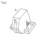
- Reference numeral 9 designates a fixed bead guide for guiding the bead between the planing blade 1 and a rotary bead chopper 3.
- the principal portion of the present invention relates to combination of the guide shoe B and bead guide 9, in which reference numeral 10 designates a stationary blade so that the weld bead C is chopped into small pieces between the stationary blade 10 and the bead chopper 3.
- the bead guide 9, stationary blade 10 and rotary bead chopper 3 are supported to a block 11.
- the block 11 is inserted into a stand 12 and movable up and down for positional adjustment when a pipe diameter is changed.
- Reference numeral 14 designates a drive motor for vertically moving the block 11, the block 11 being moved up and down by a gear 15 and a screw mechanism, 13 designates a pneumatic cylinder operated when the planing blade 1 is required to escape in emergency because the vertically movable drive motor 14 is not enough to be in time, and the block 11 being further provided with a guide cover 27 for preventing the dropped weld beads from scattering on all sides, and for collecting them into a waste bucket or a waste discharge conveyor (not shown).
- a cushion plate 16 Between the stand 12 and a base plate 24 is inserted a cushion plate 16 for preventing vibrations and impact during the rotation of chopper 3 from being transmitted to other parts.
- Fig. 3 in a detailed view shows that the weld bead C is planed off from the electric seamed steel pipe A by the planing blade 1, guided upwardly forwardly by the guide shoe B fixed to the planing blade holder 2, and guided between the rotary bead chopper 3 and the stationary blade 10 through the bead guide 9, at which time unless an extending distance from the planing blade 1 to the rotary bead chopper 3 is less than 100 mm, a stable movement path of weld bead cannot be ensured, which is obtained from the experiment.
- the planing blade 1 is fixed to the planing blade holder 2 fixedly slant-wise connected to the block 4 through a connecting bolt, the guide shoe B being fixed by the same bolt to the block 4 together with the planing blade 1 and being provided at the lower end with a guide surface slanted to upwardly bend the weld bead C.
- the bead guide 9 is shown, which guides the weld bead C planed, upwardly bent and turned in the direction is further guided toward the rotary bead chopper 3 and stationary blade 10 along a guide groove 9a disposed just behind the guide shoe B, the rotary bead chopper 3 and stationary blade 10 being disposed outside the outlet of guide groove 9a.
- the present invention constructed as the above-mentioned has the following effect.
- the weld bead C is planed from the steel pipe A by the planing blade 1, upwardly forwardly guided by the guide shoe B fixedly provided at the planing blade holder 2, and automatically guided between the stationary blade 10 and the bead chopper 3 rotatable through the short guide 9, so that there is no need for the operator to manually guide the weld bead, thereby not causing the danger to occur labor accident.
- each rotary bead chopper 3 is chopped into small pieces and continuously discharged through the guide cover 27 into the waste bucket or the waste discharge conveyor disposed below, whereby it is never hindered that the electric-seamed steel pipe manufacturing equipment is operated continuously for a long time.
- the present invention is recognized to be technique of demonstrating an extremely useful effect.
Landscapes
- Engineering & Computer Science (AREA)
- Mechanical Engineering (AREA)
- Milling, Broaching, Filing, Reaming, And Others (AREA)
Claims (3)
- Schweißwulst-Schneidvorrichtung für eine Anlage zum Herstellen eines elektronahtgeschweißten Stahlrohrs (A) durch kontinuierliches Rundformen von Metallblechmaterial und Schweißen einer Naht, umfassend:eine Schweißwulst-Schneideinheit mit einem Hobelmesser (1) zum kontinuierlichen Abhobeln eines von einer Nahtschweißzone vorstehenden Schweißwulsts (C),einen Dreh-Wulstzerhacker (3) zum kontinuierlichen Zerhacken des vom Hobelmesser (1) abgehobelten Schweißwulstes (C) in kleine Stücke, undeine zwischen dem Hobelmesser (1) und dem Dreh-Wulstzerhacker (3) vorgesehene Wulstführung (9),
dadurch gekennzeichnet, daß die Wulstführung (9) mit einer Führungsnut bzw. -rille (9a) versehen ist, entlang der der abgehobelte Schweißwulst (C) geführt wird. - Schweißwulst-Schneidvorrichtung nach Anspruch 1, dadurch gekennzeichnet, daß ein Führungsschuh (B) feststehend zwischen dem Hobelmesser (1) und der Wulstführung (9) zum Führen des abgehobelten Schweißwulstes (C) nach oben und nach vorne vorgesehen ist.
- Schweißwulst-Schneidvorrichtung nach Anspruch 1, dadurch gekennzeichnet, daß eine Länge des Schweißwulstes (C) zwischen dem Hobelmesser (1) und dem Wulstzerhacker (3) weniger als 100 mm beträgt.
Applications Claiming Priority (2)
| Application Number | Priority Date | Filing Date | Title |
|---|---|---|---|
| JP317666/92 | 1992-11-27 | ||
| JP4317666A JPH06155134A (ja) | 1992-11-27 | 1992-11-27 | 溶接ビードカッター機構 |
Publications (2)
| Publication Number | Publication Date |
|---|---|
| EP0600394A1 EP0600394A1 (de) | 1994-06-08 |
| EP0600394B1 true EP0600394B1 (de) | 1999-01-27 |
Family
ID=18090678
Family Applications (1)
| Application Number | Title | Priority Date | Filing Date |
|---|---|---|---|
| EP93119124A Expired - Lifetime EP0600394B1 (de) | 1992-11-27 | 1993-11-26 | Schweisswulstschneidvorrichtung |
Country Status (4)
| Country | Link |
|---|---|
| US (1) | US5368218A (de) |
| EP (1) | EP0600394B1 (de) |
| JP (1) | JPH06155134A (de) |
| DE (2) | DE600394T1 (de) |
Families Citing this family (11)
| Publication number | Priority date | Publication date | Assignee | Title |
|---|---|---|---|---|
| DE19728435C2 (de) * | 1997-07-03 | 1999-11-18 | Dreistern Werk Maschinenbau Gm | Vorrichtung zum Abtragen einer Schweißnahtüberhöhung |
| US6158646A (en) * | 1998-12-11 | 2000-12-12 | Empire Precision Tooling Inc. | Weld bead chopper |
| DE10112294A1 (de) * | 2001-03-08 | 2002-09-19 | Sms Meer Gmbh | Vorrichtung zum Abführen und Zerkleinern des in einer Rohrschweißanlage von der äußeren Rohroberfläche abgetragenen Spanes |
| US7695224B2 (en) | 2008-01-31 | 2010-04-13 | Lumco Manufacturing Company | Deburring welded pipe |
| US7988029B2 (en) * | 2008-12-11 | 2011-08-02 | Lumco Manufacturing Company | External deburring of welded pipe |
| US20130098220A1 (en) * | 2011-10-21 | 2013-04-25 | John Seminew | External bead scarfer and chopper for pipes and tubes |
| US9713831B2 (en) * | 2013-08-29 | 2017-07-25 | Quartz Matrix, LLC | Chopper and external weld bead removal system including same |
| DE102014011002B3 (de) * | 2014-07-29 | 2015-12-24 | Sms Meer Gmbh | Vorrichtung und Verfahren zum Abführen und Zerkleinern eines Spans |
| CN106564032B (zh) * | 2016-10-29 | 2018-03-30 | 安徽旭虹机械设备有限公司 | 一种桶柄装配用装配器 |
| CN108942238A (zh) * | 2018-08-24 | 2018-12-07 | 无锡苏嘉宇正自动化设备科技有限公司 | 焊管外毛刺自动切断机 |
| CN117548728A (zh) * | 2022-08-05 | 2024-02-13 | 山东华舜重工集团有限公司 | 一种焊管刮疤装置及刮疤方法 |
Family Cites Families (14)
| Publication number | Priority date | Publication date | Assignee | Title |
|---|---|---|---|---|
| US3148647A (en) * | 1962-01-25 | 1964-09-15 | Tex Tube Inc | Tube-forming machine |
| JPS50154890A (de) * | 1974-06-05 | 1975-12-13 | ||
| JPS5295389A (en) * | 1976-02-07 | 1977-08-10 | Nippon Steel Corp | Device for cutting beads on the inner surface of the tube |
| JPS5344449A (en) * | 1976-10-04 | 1978-04-21 | Sumitomo Metal Ind | Process for fabricating steel tubes by high frequency welding |
| SU649196A1 (ru) * | 1976-11-15 | 1981-02-28 | Предприятие П/Я В-2869 | Устройство дл сн ти грата |
| AT372321B (de) * | 1980-08-04 | 1983-09-26 | Voest Alpine Ag | Verfahren und vorrichtung zum abtragen des aussenschweissgrates laengsgeschweisster rohre |
| JPS6037215A (ja) * | 1983-08-08 | 1985-02-26 | Sumitomo Metal Ind Ltd | 電縫鋼管の連続製造方法とその装置 |
| DE3405479A1 (de) * | 1984-02-16 | 1985-08-22 | Stolberger Metallwerke GmbH & Co KG von Asten, Lynen & Schleicher, 5190 Stolberg | Verfahren zur kontinuierlichen herstellung profilierter metallbaender |
| JPS61147989A (ja) * | 1984-12-21 | 1986-07-05 | Nisshin Steel Co Ltd | 金属被覆鋼管のビ−ドカツト溶射部補修方法 |
| JPS61209811A (ja) * | 1985-03-13 | 1986-09-18 | Sumitomo Metal Ind Ltd | 鋼管内部の切粉屑処理装置 |
| JPS62236647A (ja) * | 1986-03-31 | 1987-10-16 | Kobe Steel Ltd | チツプ処理装置 |
| JPH0677774B2 (ja) * | 1986-04-18 | 1994-10-05 | 日新製鋼株式会社 | 溶接ビ−ド切削部が補修されたアルミニウム系被覆電縫鋼管の製造方法 |
| JPS62277213A (ja) * | 1986-05-26 | 1987-12-02 | Nippon Steel Corp | 電縫鋼管外面ビ−ド連続処理装置 |
| US5216792A (en) * | 1990-06-30 | 1993-06-08 | Hoesch Aktiengesellschaft | Method of and device for obtaining short shavings trimmed from the seams inside longitudinally welded pipes |
-
1992
- 1992-11-27 JP JP4317666A patent/JPH06155134A/ja active Pending
-
1993
- 1993-07-01 US US08/084,478 patent/US5368218A/en not_active Expired - Lifetime
- 1993-11-26 DE DE0600394T patent/DE600394T1/de active Pending
- 1993-11-26 EP EP93119124A patent/EP0600394B1/de not_active Expired - Lifetime
- 1993-11-26 DE DE69323277T patent/DE69323277T2/de not_active Expired - Lifetime
Also Published As
| Publication number | Publication date |
|---|---|
| JPH06155134A (ja) | 1994-06-03 |
| EP0600394A1 (de) | 1994-06-08 |
| US5368218A (en) | 1994-11-29 |
| DE69323277D1 (de) | 1999-03-11 |
| DE600394T1 (de) | 1995-04-20 |
| DE69323277T2 (de) | 1999-07-08 |
Similar Documents
| Publication | Publication Date | Title |
|---|---|---|
| EP1142787B1 (de) | Verfahren und Vorrichtung zum Umhüllen von Gegenständen | |
| EP0600394B1 (de) | Schweisswulstschneidvorrichtung | |
| CN114803616B (zh) | 起头处理装置及换卷设备 | |
| US3377687A (en) | Debanding device for rolled coils | |
| US3246553A (en) | Scrap chopper | |
| CN115464397A (zh) | 一种金属管套卷圆焊接装置 | |
| US6158646A (en) | Weld bead chopper | |
| KR100544428B1 (ko) | 코일밴드 자동 제거장치 | |
| US4266989A (en) | Cutting tool guiding system for metal cutting machines | |
| CN223704604U (zh) | 一种纺织带切断机 | |
| KR100544471B1 (ko) | 코일 외권의 밴드 자동제거장치 | |
| JP3648257B2 (ja) | マニピュレータ及び帯材の操作方法 | |
| GB2046147A (en) | Coil Band Severing and Disposal Apparatus | |
| JPH07156099A (ja) | 紙管切断機 | |
| US5890645A (en) | Continuous feed wire uncoiler | |
| JPH07101641A (ja) | テープ巻き付け装置 | |
| JPH0761586B2 (ja) | 板金加工機 | |
| CN219839272U (zh) | 切割设备 | |
| JP2001150189A (ja) | 電縫管の外面ビード切屑の切断方法及び外面ビード切屑切断装置 | |
| KR200173984Y1 (ko) | 코일 절단장치 | |
| KR100822973B1 (ko) | 선행강판과 후행강판의 접속 폭 차 감소장치 | |
| CN214187358U (zh) | 一种用于塑料薄膜生产的纸筒自动分切装置 | |
| KR200206001Y1 (ko) | 보호판 절단장치 | |
| CN220547720U (zh) | 一种定长自定卷料机 | |
| CN114864272B (zh) | 绕线机 |
Legal Events
| Date | Code | Title | Description |
|---|---|---|---|
| PUAI | Public reference made under article 153(3) epc to a published international application that has entered the european phase |
Free format text: ORIGINAL CODE: 0009012 |
|
| AK | Designated contracting states |
Kind code of ref document: A1 Designated state(s): DE |
|
| 17P | Request for examination filed |
Effective date: 19941128 |
|
| DET | De: translation of patent claims | ||
| 17Q | First examination report despatched |
Effective date: 19970304 |
|
| GRAG | Despatch of communication of intention to grant |
Free format text: ORIGINAL CODE: EPIDOS AGRA |
|
| GRAG | Despatch of communication of intention to grant |
Free format text: ORIGINAL CODE: EPIDOS AGRA |
|
| GRAH | Despatch of communication of intention to grant a patent |
Free format text: ORIGINAL CODE: EPIDOS IGRA |
|
| GRAH | Despatch of communication of intention to grant a patent |
Free format text: ORIGINAL CODE: EPIDOS IGRA |
|
| GRAA | (expected) grant |
Free format text: ORIGINAL CODE: 0009210 |
|
| AK | Designated contracting states |
Kind code of ref document: B1 Designated state(s): DE |
|
| REF | Corresponds to: |
Ref document number: 69323277 Country of ref document: DE Date of ref document: 19990311 |
|
| PLBE | No opposition filed within time limit |
Free format text: ORIGINAL CODE: 0009261 |
|
| STAA | Information on the status of an ep patent application or granted ep patent |
Free format text: STATUS: NO OPPOSITION FILED WITHIN TIME LIMIT |
|
| 26N | No opposition filed | ||
| PGFP | Annual fee paid to national office [announced via postgrant information from national office to epo] |
Ref country code: DE Payment date: 20100129 Year of fee payment: 17 |
|
| REG | Reference to a national code |
Ref country code: DE Ref legal event code: R119 Ref document number: 69323277 Country of ref document: DE Effective date: 20110601 Ref country code: DE Ref legal event code: R119 Ref document number: 69323277 Country of ref document: DE Effective date: 20110531 |
|
| PG25 | Lapsed in a contracting state [announced via postgrant information from national office to epo] |
Ref country code: DE Free format text: LAPSE BECAUSE OF NON-PAYMENT OF DUE FEES Effective date: 20110531 |