EP0600409B1 - Unité de disques magnétiques - Google Patents
Unité de disques magnétiques Download PDFInfo
- Publication number
- EP0600409B1 EP0600409B1 EP93119204A EP93119204A EP0600409B1 EP 0600409 B1 EP0600409 B1 EP 0600409B1 EP 93119204 A EP93119204 A EP 93119204A EP 93119204 A EP93119204 A EP 93119204A EP 0600409 B1 EP0600409 B1 EP 0600409B1
- Authority
- EP
- European Patent Office
- Prior art keywords
- arm holder
- bearings
- sleeve
- magnetic disk
- disk unit
- Prior art date
- Legal status (The legal status is an assumption and is not a legal conclusion. Google has not performed a legal analysis and makes no representation as to the accuracy of the status listed.)
- Expired - Lifetime
Links
- 239000000463 material Substances 0.000 claims description 15
- 101000606504 Drosophila melanogaster Tyrosine-protein kinase-like otk Proteins 0.000 description 17
- XAGFODPZIPBFFR-UHFFFAOYSA-N aluminium Chemical compound [Al] XAGFODPZIPBFFR-UHFFFAOYSA-N 0.000 description 10
- 239000010935 stainless steel Substances 0.000 description 10
- 229910001220 stainless steel Inorganic materials 0.000 description 10
- 229910000861 Mg alloy Inorganic materials 0.000 description 6
- 229910000831 Steel Inorganic materials 0.000 description 6
- 229910052782 aluminium Inorganic materials 0.000 description 6
- 239000010959 steel Substances 0.000 description 6
- 238000000034 method Methods 0.000 description 5
- 229910000838 Al alloy Inorganic materials 0.000 description 3
- 229910045601 alloy Inorganic materials 0.000 description 3
- 239000000956 alloy Substances 0.000 description 3
- 230000001965 increasing effect Effects 0.000 description 3
- 230000035882 stress Effects 0.000 description 3
- 230000008646 thermal stress Effects 0.000 description 3
- FYYHWMGAXLPEAU-UHFFFAOYSA-N Magnesium Chemical compound [Mg] FYYHWMGAXLPEAU-UHFFFAOYSA-N 0.000 description 2
- 239000011777 magnesium Substances 0.000 description 2
- 229910052749 magnesium Inorganic materials 0.000 description 2
- 229910000734 martensite Inorganic materials 0.000 description 2
- 238000005259 measurement Methods 0.000 description 2
- XUIMIQQOPSSXEZ-UHFFFAOYSA-N Silicon Chemical compound [Si] XUIMIQQOPSSXEZ-UHFFFAOYSA-N 0.000 description 1
- 230000001133 acceleration Effects 0.000 description 1
- 238000007792 addition Methods 0.000 description 1
- 230000015572 biosynthetic process Effects 0.000 description 1
- 238000006073 displacement reaction Methods 0.000 description 1
- 230000002708 enhancing effect Effects 0.000 description 1
- 230000005484 gravity Effects 0.000 description 1
- 238000012986 modification Methods 0.000 description 1
- 230000004048 modification Effects 0.000 description 1
- 229910052710 silicon Inorganic materials 0.000 description 1
- 239000010703 silicon Substances 0.000 description 1
- 238000004088 simulation Methods 0.000 description 1
Images



Classifications
-
- G—PHYSICS
- G11—INFORMATION STORAGE
- G11B—INFORMATION STORAGE BASED ON RELATIVE MOVEMENT BETWEEN RECORD CARRIER AND TRANSDUCER
- G11B5/00—Recording by magnetisation or demagnetisation of a record carrier; Reproducing by magnetic means; Record carriers therefor
- G11B5/48—Disposition or mounting of heads or head supports relative to record carriers ; arrangements of heads, e.g. for scanning the record carrier to increase the relative speed
- G11B5/54—Disposition or mounting of heads or head supports relative to record carriers ; arrangements of heads, e.g. for scanning the record carrier to increase the relative speed with provision for moving the head into or out of its operative position or across tracks
- G11B5/55—Track change, selection or acquisition by displacement of the head
- G11B5/5521—Track change, selection or acquisition by displacement of the head across disk tracks
- G11B5/5565—Track change, selection or acquisition by displacement of the head across disk tracks system adaptation for compensation of variations of physical parameters, e.g. temperature
-
- G—PHYSICS
- G11—INFORMATION STORAGE
- G11B—INFORMATION STORAGE BASED ON RELATIVE MOVEMENT BETWEEN RECORD CARRIER AND TRANSDUCER
- G11B25/00—Apparatus characterised by the shape of record carrier employed but not specific to the method of recording or reproducing, e.g. dictating apparatus; Combinations of such apparatus
- G11B25/04—Apparatus characterised by the shape of record carrier employed but not specific to the method of recording or reproducing, e.g. dictating apparatus; Combinations of such apparatus using flat record carriers, e.g. disc, card
- G11B25/043—Apparatus characterised by the shape of record carrier employed but not specific to the method of recording or reproducing, e.g. dictating apparatus; Combinations of such apparatus using flat record carriers, e.g. disc, card using rotating discs
-
- G—PHYSICS
- G11—INFORMATION STORAGE
- G11B—INFORMATION STORAGE BASED ON RELATIVE MOVEMENT BETWEEN RECORD CARRIER AND TRANSDUCER
- G11B33/00—Constructional parts, details or accessories not provided for in the other groups of this subclass
- G11B33/14—Reducing influence of physical parameters, e.g. temperature change, moisture, dust
- G11B33/1493—Electro-Magnetic Interference [EMI] or Radio Frequency Interference [RFI] shielding; grounding of static charges
Definitions
- This invention relates to a magnetic disk unit, and particularly to a magnetic disk unit capable of making high precision reading and writing by magnetic heads with a thermal offtrack minimized.
- This type of magnetic disk unit generally has a magnetic head mounted on a rotary carriage and floats the magnetic head from the surface of a magnetic disk by an air pressure generated by the magnetic disk revolving at a high speed to read or write magnetic record from or to the magnetic disk.
- a carriage of the magnetic disk unit is designed to read a positioning pattern written in the surface of a magnetic disk with a servo head and to form a servo loop for positioning.
- Such a magnetic disk unit has been improved to enhance recording density.
- Methods for enhancing the recording density includes a method to increase the track bit density and a method to increase the track density by reducing the track width. In recent years, the track width has been reduced to about 10 micrometers.
- Fig. 4 shows an example of a conventional magnetic disk unit.
- magnetic disks are rotatably supported on a base 43 with both ends of a disk rotating shaft 42 via a spindle hub 44 and bearings 45a, 45b.
- a plurality of magnetic heads 49 which are disposed to face the magnetic disks 41 are supported by an arm holder 52.
- the arm holder 52 is fixed to bearings 54a, 54b and rotatably supported by a head rotating shaft 53 via the bearings 54a, 54b.
- the magnetic heads 49 can be driven to rotate by a torque generated by a magnetic circuit 57.
- the magnetic heads 49 consist of servo heads 48 used for positioning and data heads 47 for reading and writing data.
- the arm holder 52 has a plurality of arms 50 which support the data heads 47 and the servo heads 48.
- the servo head 48 faces a disk surface 41a set with a positioning track having a positioning data written. Data other than the positioning data is not written in the positioning track of the disk surface 41a.
- the bottom face of the third disk from the top is used as the disk surface 41a for setting the positioning track. It is optional wherever the positioning track is set and, the position of the servo head 48 is fixed accordingly.
- the causes of the offtrack are considered to be as follows.
- a material for the arm holder 52 supporting the servo head 48 and the data head 47 is aluminum or magnesium which is inexpensive and light, and has suitable strength.
- a material for the outer ring of the bearings 54a, 54b ball-bearing steel or martensite-based stainless steel is used to enhance accuracy.
- the inner diameter size of the arm holder 52 and the outer diameter size of the outer ring of the bearings 54a, 54b are increased due to thermal expansion when the temperature of the environment in which the magnetic disk unit is installed increases.
- the ball-bearing steel or martensite-based stainless steel which is the material for the outer ring of the bearings 54a, 54b has a coefficient of linear expansion which is about half of that of the aluminum or magnesium which is the material for the arm holder 52, so that the thermal deformation of the bearings 54a, 54b is not as large as that of the arm holder 52 is.
- the arm holder 52 is pulled in a direction (inward in the radial direction of the bearings 54a, 54b) that expansion is prevented by the bearings 54a, 54b, at a position that the bearings 54a, 54b are fixed.
- the arm holder 52 is deformed as a whole because distortion is applied in the same direction as the radial direction of the bearings 54a, 54b.
- the arm 50 which is at a position where the arm holder 52 is in contact with the bearings 54a, 54b, is particularly largely deformed in the radial direction of the bearings 54a, 54b, i.e., in a direction causing an offtrack, as compared with the arm 50 at another position. Therefore, as shown in the thermal offtrack characteristics of Fig. 5, the data head 47, which is mounted on the arm 50 at a position to contact with the bearings 54a, 54b, is largely displaced, resulting in causing an offtrack.
- US-A-4,754,353 discloses a hard disk read positioner according to the preamble of claim 1.
- An object of this invention is to provide a magnetic disk unit which is free from the aforementioned existing drawbacks and can remedy the thermal offtrack by, in case of thermal expansion of an arm holder and bearings, absorbing distortion caused by the thermal expansion, to make the deformation of the arm holder equal to those of a servo arm and a data arm so as to minimize a relative position change of the servo head and the data head.
- Fig. 1 is a longitudinal sectional view showing a magnetic disk unit according to the first embodiment of this invention.
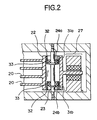
- Fig. 2 is a longitudinal sectional view showing a magnetic disk unit according to the second embodiment of this invention.
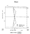
- Fig. 3 is a chart showing thermal offtrack characteristics of this invention.
- Fig. 4 is a longitudinal sectional view showing a conventional magnetic disk unit.
- Fig. 5 is a chart showing thermal offtrack characteristics of a conventional magnetic disk unit.
- Fig. 1 shows a magnetic disk unit of the first embodiment of this invention.
- magnetic disks 11 are rotatably supported on a base 13 with both ends of a disk rotating shaft 12 via a spindle hub 14 and bearings 15a, 15b. Further, a plurality of magnetic heads 19, which are disposed to face the magnetic disks 11, are supported by an arm holder 22.
- the arm holder 22 is rotatably supported by a head rotating shaft 23 via a pair of bearings 24a, 24b disposed in a vertical relation. Further, the magnetic heads 19 can be driven for rotation by a torque generated by a magnetic circuit 27.
- the magnetic heads 19 consist of servo heads 18 used for positioning and data heads 17 for data reading and writing.
- the arm holder 22 has a plurality of arms 20 to support the data heads 17 and the servo heads 18.
- the servo head 18 faces a disk surface 11a among the disk 11 set with a positioning track having a positioning data written. Data other than the positioning data is not written in the positioning track of the disk surface lla.
- the bottom face of the third disk from the top is used as the disk surface lla for setting the positioning track.
- a pipe sleeve 28 is disposed fixed to the arm holder 22 by shrink fitting or bonding.
- the sleeve 28 has thick wall parts 28a, 28b having a specified width which are formed by increasing the wall thickness of its top and bottom ends. Therefore, a portion between the thick wall parts 28a, 28b of the sleeve 28 is formed to have a wall thickness smaller than the thick wall parts 28a, 28b.
- the outer periphery sections of the thick wall parts 28a, 28b are fixed to the inner periphery of the arm holder 22. Also, the outer periphery sections of the bearings 24a, 24b are fixed to the inner periphery of the sleeve 28.
- the wall thickness of the sleeve 28 is desirably formed to have an inevitable minimum size to bear a stress generated by distortion due to a difference of expansion according to a temperature change in the sleeve 28 and the bearings 24a, 24b and a stress generated during seeking by an actuator.
- distortion of the arm holder 22 can be minimized.
- Disposition of the thus shaped sleeve 28 permits formation of a gap 30 along the entire outer periphery between the sleeve 28 and the arm holder 22 due to the difference of the wall thickness between the thick wall parts 28a, 28b and the thin wall part therebetween excepting the portions of the thick wall parts 28a, 28b.
- This gap 30 extends to sections where the sleeve 28 contacts the bearings 24a, 24b. In other words, the gap 30 is positioned at the outer periphery of the parts where the sleeve 28 contacts the bearings 24a, 24b.
- the sleeve 28 itself is affected by the thermal distortion of the bearings 24a, 24b, the relative positional displacement of the servo heads 18 and the data heads 17, or the offtrack, which is caused due to the thermal distortion of the arm holder 22, can be directly reduced relatively easily by analyzing the material, size and shape of the sleeve 28 and its contact part with the arm holder 22 by the finite element method so as to optimize them.
- the disposition of the sleeve 28 may result in a bimetal action which is generated by a difference of thermal distortion between the sleeve 28 and the arm holder 22 and a difference of thermal distortion in the axial direction between these members to deform the arm holder 22. Therefore, it is necessary to remove this disadvantage effectively.
- the gap 30 is disposed not only at sections contacting to the bearings 24a, 24b but also along almost the entire area in the axial direction of the sleeve 28 as shown in Fig. 1, and aluminum (Al) is used to form the arm holder 22 and the sleeve 28 and ball-bearing steel is used to form the bearings 24a, 24b.
- magnesium alloy may be used for the arm holder 22, stainless steel for the bearings 24a, 24b, and magnesium alloy or stainless steel for the sleeve 28.
- the magnesium alloy is easily rusted but the specific gravity is small, and has the same specific strength as aluminum, so that it is useful for speeding up of the actuator.
- Stainless steel has such characteristics that it is hardly rusted as compared with the ball-bearing steel and has higher strength than aluminum and magnesium alloy.
- Table 1 shows setting examples of the materials for the arm holder 22, the bearings 24a, 24b and the sleeve 28 in detail.
- Setting example 1 Arm holder Bearing Sleeve Material Aluminum Ball-bearing steel Stainless steel Coefficient of linear expansion (10 -6 mm/°C) 23.4 11.9 17.3
- Setting example 2 Arm holder Bearing Sleeve Material Magnesium alloy Stainless steel Aluminum powder alloy Coefficient of linear expansion (10 -6 mm/°C) 27.0 10.1 13 - 18
- aluminum having a coefficient of linear expansion of 23.4x10 -6 mm/°C is used for the arm holder 22, ball-bearing steel having a coefficient of linear expansion of 11.9x10 -6 mm/°C for the bearings 24a, 24b, and stainless steel having a coefficient of linear expansion of 17.3x10 -6 mm/°C for the sleeve 28.
- magnesium alloy having a coefficient of linear expansion of 27.0x10 -6 mm/°C is used for the arm holder 22, stainless steel having a coefficient of linear expansion of 10.1x10 -6 mm/°C for the bearings 24a, 24b, and aluminum powder alloy for the sleeve 28.
- the aluminum powder alloy for the sleeve 28 used in the second setting example has its silicon content adjusted suitably to vary its coefficient of linear expansion in the range of from 13.0x10 -6 mm/°C to 18.0x10 -6 mm/°C.
- the materials for the sleeve 28 are not limited to those shown in Table 1.
- any material having the same coefficient of linear expansion with that of the arm holder 22 may be selected. In this case, good thermal offtrack characteristics can also be obtained.
- Fig. 3 shows a measured example of thermal offtrack characteristics obtained when the embodiment constructed as described above is applied to a 5.25-inch hard disk drive.
- the arm holder 22 has a wall thickness A of 2.3 mm
- the sleeve 28 has a wall thickness B of 0.6 mm which is to form the gap 30, and the gap 30 has a width C of 0.1 mm as shown in Fig. 1.
- the arm holder 22 is made of aluminum alloy having a coefficient of linear expansion of 23.4x10 -6 mm/°C
- the bearings 24a, 24b are made of stainless steel having a coefficient of linear expansion of 11.9x10 -6 mm/°C
- the sleeve 28 is made of aluminum alloy having a coefficient of linear expansion of 23.6x10 -6 mm/°C.
- a thermal stress applied to the sleeve 28 owing to a temperature change is 25.48 kg/mm at -40 °C and 10.66 kg/mm at 80 °C obtained by calculating by the finite element method. Therefore, the thermal stress applied to the sleeve 28 is below the tensile strength of the sleeve 28 and is a value not causing any problem. Also, a stress, which is applied to the sleeve 28 owing to acceleration at a time of seeking, is very small as compared with the above thermal stress due to a temperature change. Therefore, it can be neglected.
- Data was written immediately after starting (at a low temperature) the magnetic disk unit at an environment temperature of 5 °C, and data was read when continuously operating (at a high temperature) at an environment temperature of 50 °C.
- Fig. 3 was compared with Fig. 5 showing offtrack errors of a conventional magnetic disk unit.
- the offtrack errors were lowered from about 5 ⁇ m of prior art to 1 ⁇ m. Thus, quite good results were obtained.
- Fig. 2 shows a magnetic disk unit according to the second embodiment of this invention.
- this embodiment has two sleeves 31a, 31b disposed corresponding to bearings 24a, 24b, respectively.
- the sleeves 31a, 31b each have the shape of a pipe and a length in the axial direction about two times of the bearings 24a, 24b, and also have a thick wall part 32 which is formed by partly increasing the thickness.
- the outer periphery part of the thick wall part 32 is fixed to the inner periphery of an arm holder 22.
- a gap 33 is formed along the entire outer periphery areas of the sleeves 31a, 31b excepting the areas of the thick wall parts 32 of the sleeves 31a, 31b.
- the outer peripheries of the bearings 24a, 24b are fixed to the inner peripheries of the sleeves 31a, 31b at the parts that the gaps 33 are formed.
- the sleeves 31a, 31b are designed as independent plural parts and corresponded to the respective bearings 24a, 24b, so that a difference of thermal distortion in the radial direction of the arm holder 22 and the bearings 24a, 24b generated owing to a temperature change is absorbed by the gaps 33 of the sleeves 31a, 31b. Also, since the sleeves 31a, 31b are independent parts, thermal distortion generated in the axial direction due to a temperature change depending on a difference of coefficient of linear expansion between the arm holder 22 and the sleeves 31a, 31b becomes very small. In other words, deformation due to the bimetal action is substantially nil, and better thermal offtrack characteristics than in the first embodiment can be obtained.
Landscapes
- Moving Of Heads (AREA)
Claims (8)
- Unité de disques magnétiques, comprenant :caractérisée par :des disques magnétiques (11) montés rotatifs sur un axe (12) de rotation de disques,un support de bras (22) sensiblement cylindrique, ayant des bras (20) de positionnement de têtes correspondant auxdits disques magnétiques dans la direction axiale et qui est supporté, de manière à tourner autour d'un axe, par un axe (23) de rotation de têtes disposé en parallèle avec ledit axe de rotation de disques avec une pluralité de coussinets (24a, 24b) disposés entre eux, etdes têtes magnétiques (19) montées sur des bras dudit support de bras (22) et disposées pour faire face aux surfaces desdits disques magnétiques (11),un manchon cylindrique (28, 31a, 31b) disposé entre lesdits coussinets (24a, 24b) et ledit support de bras (22) et ayant des parties de paroi d'épaisseurs différentes pour former un vide (30) entre la périphérie extérieure du manchon et la périphérie intérieure dudit support de bras, ledit vide (30) s'étendant à des sections où le manchon est en contact avec les coussinets, pour absorber une différence de distorsions thermiques dans la direction radiale dudit support de bras et desdits coussinets.
- Unité de disques magnétiques selon la revendication 1, dans laquelle ledit manchon (28, 31a, 31b) a des parties épaisses (28a, 28b, 32) de paroi destinées à être fixées à la périphérie intérieure dudit support de bras (22) et une partie mince de paroi pour former un vide (30) avec la périphérie intérieure dudit support de bras, et les périphéries extérieures desdits coussinets (24a, 24b) sont fixées à ladite partie mince de la paroi.
- Unité de disques magnétiques selon la revendication 1 ou 2, dans laquelle ledit manchon (28) présente une forme cylindrique unique ayant sensiblement la même longueur dans la direction axiale que ledit support de bras (22) et a des parties épaisses (28a, 28b) de paroi à ses extrémités supérieure et inférieure destinées à être fixées à la périphérie intérieure dudit support de bras (22) et une partie mince de paroi pour former un vide (30) avec la périphérie intérieure dudit support de bras, et les périphéries extérieures desdits coussinets (24a, 24b) sont fixées à ladite partie mince de la paroi.
- Unité de disques magnétiques selon la revendication 1, 2 ou 3, dans laquelle une pluralité desdits manchons (31a, 31b) présente une forme cylindrique avec une longueur dans la direction axiale plus courte que celle dudit support de bras (22) et disposée entre lesdits coussinets (24a, 24b) et ledit support de bras (22) correspondant à ladite pluralité de coussinets respectifs, et a des parties épaisses (32) de paroi destinées à être fixées à la périphérie intérieure dudit support de bras (22) et des parties minces de paroi pour former un vide (30) avec la périphérie intérieure dudit support de bras, et les périphéries extérieures desdits coussinets sont fixées auxdites parties minces de paroi.
- Unité de disques magnétiques selon la revendication 2, dans laquelle ledit manchon (28) présente une forme cylindrique unique ayant sensiblement la même longueur dans la direction axiale que ledit support de bras (22) et ayant ses deux extrémités formées dans ladite partie épaisse de paroi et sa partie moyenne formée dans ladite partie mince de paroi.
- Unité de disques magnétiques selon l'une quelconque des revendications 1 à 5, dans laquelle ledit manchon (28) est en un matériau dont le coefficient de dilatation linéique a une valeur comprise entre celles dudit support de bras (22) et desdits coussinets (24a, 24b).
- Unité de disques magnétiques selon l'une quelconque des revendications 1 à 6, dans laquelle ledit manchon (28) est en un matériau ayant le même coefficient de dilatation linéique que ledit support de bras (22).
- Unité de disques magnétiques selon l'une quelconque des revendications 1 à 7, dans laquelle ledit manchon (28) a une épaisseur de paroi de grandeur minimale inévitable suffisante pour résister à une contrainte produite par une déformation due à une différence de dilatation provoquée par un changement de température dans ledit manchon et lesdits coussinets (24a, 24b) et à une contrainte produite pendant un positionnement.
Applications Claiming Priority (2)
| Application Number | Priority Date | Filing Date | Title |
|---|---|---|---|
| JP4343446A JP2671738B2 (ja) | 1992-11-30 | 1992-11-30 | 磁気ディスク装置 |
| JP343446/92 | 1992-11-30 |
Publications (3)
| Publication Number | Publication Date |
|---|---|
| EP0600409A2 EP0600409A2 (fr) | 1994-06-08 |
| EP0600409A3 EP0600409A3 (en) | 1994-09-21 |
| EP0600409B1 true EP0600409B1 (fr) | 1998-10-07 |
Family
ID=18361580
Family Applications (1)
| Application Number | Title | Priority Date | Filing Date |
|---|---|---|---|
| EP93119204A Expired - Lifetime EP0600409B1 (fr) | 1992-11-30 | 1993-11-29 | Unité de disques magnétiques |
Country Status (4)
| Country | Link |
|---|---|
| US (1) | US5463515A (fr) |
| EP (1) | EP0600409B1 (fr) |
| JP (1) | JP2671738B2 (fr) |
| DE (1) | DE69321442T2 (fr) |
Families Citing this family (4)
| Publication number | Priority date | Publication date | Assignee | Title |
|---|---|---|---|---|
| US5805385A (en) * | 1993-05-28 | 1998-09-08 | Nec Corporation | Magnetic disk device |
| JP3032151B2 (ja) * | 1996-03-18 | 2000-04-10 | 株式会社東芝 | 軸受ユニット、これを備えたキャリッジアッセンブリ、および磁気ディスク装置 |
| JP3758757B2 (ja) * | 1996-09-06 | 2006-03-22 | ヒタチグローバルストレージテクノロジーズネザーランドビーブイ | ディスク装置 |
| US20260112389A1 (en) * | 2024-10-23 | 2026-04-23 | Western Digital Technologies, Inc. | Bearing span reduction with coil thickness increase for improved actuator structural dynamics in hard disk drive |
Family Cites Families (12)
| Publication number | Priority date | Publication date | Assignee | Title |
|---|---|---|---|---|
| DE3404223A1 (de) * | 1984-02-07 | 1985-08-08 | Siemens AG, 1000 Berlin und 8000 München | Gehaeuse fuer einen magnetplattenspeicher mit beidseitig gelagertem plattenstapel |
| DE3404241A1 (de) * | 1984-02-07 | 1985-08-08 | Siemens AG, 1000 Berlin und 8000 München | Geteiltes gehaeuse fuer einen magnetplattenspeicher mit umlaufendem dichtungsring |
| JPS60205873A (ja) * | 1984-03-30 | 1985-10-17 | インタ−ナショナル ビジネス マシ−ンズ コ−ポレ−ション | 磁気デイスク装置の磁気ヘツド位置温度補償機構 |
| JPS6148179A (ja) * | 1984-08-10 | 1986-03-08 | Fujitsu Ltd | 磁気ヘツドアクチユエ−タ |
| US4754353A (en) * | 1986-12-19 | 1988-06-28 | Micropolis Corporation | Hard disk head positioner assembly |
| US5109310A (en) * | 1989-03-07 | 1992-04-28 | Alps Electric Co., Ltd. | Disk drive device with unified actuator assembly |
| JPH03254472A (ja) * | 1990-03-05 | 1991-11-13 | Fujitsu Ltd | ディスク装置のヘッドアクチュエータ構造 |
| US5146450A (en) * | 1990-06-01 | 1992-09-08 | International Business Machines Corporation | Method and apparatus for bearing to comb attachment |
| JPH04134676A (ja) * | 1990-09-25 | 1992-05-08 | Hitachi Ltd | 磁気ディスク装置のキャリッジ構造 |
| US5301078A (en) * | 1990-06-15 | 1994-04-05 | Hitachi, Ltd. | Magnetic disk unit and manufacturing method of carriage structure thereof |
| US5315465A (en) * | 1991-07-12 | 1994-05-24 | Seagate Technology, Inc. | Compliant pivot mechanism for a rotary actuator |
| US5251085A (en) * | 1991-07-17 | 1993-10-05 | Maxtor Corporation | Pivotable arm assembly with reduced thermal distortion |
-
1992
- 1992-11-30 JP JP4343446A patent/JP2671738B2/ja not_active Expired - Lifetime
-
1993
- 1993-11-29 EP EP93119204A patent/EP0600409B1/fr not_active Expired - Lifetime
- 1993-11-29 DE DE69321442T patent/DE69321442T2/de not_active Expired - Fee Related
- 1993-11-30 US US08/159,225 patent/US5463515A/en not_active Expired - Lifetime
Also Published As
| Publication number | Publication date |
|---|---|
| DE69321442D1 (de) | 1998-11-12 |
| EP0600409A3 (en) | 1994-09-21 |
| US5463515A (en) | 1995-10-31 |
| JP2671738B2 (ja) | 1997-10-29 |
| EP0600409A2 (fr) | 1994-06-08 |
| JPH06176511A (ja) | 1994-06-24 |
| DE69321442T2 (de) | 1999-04-29 |
Similar Documents
| Publication | Publication Date | Title |
|---|---|---|
| US5396386A (en) | Roll insensitive air bearing slider | |
| US6208486B1 (en) | Spindle motor flange land portion | |
| US5377060A (en) | Ultra slim data storage module utilizing plural flexible disks | |
| EP0522717B1 (fr) | Mécanisme de pivot pour actionneur rotatif de tête | |
| JP3240935B2 (ja) | 磁気ディスク装置 | |
| EP0736859A2 (fr) | Dispositif porteur de patin de vol pour un appareil à disque magnétique | |
| US7643245B2 (en) | Magnetic disc unit with gap between magnetic disc and shroud | |
| EP0441557B1 (fr) | Support rotatif dans un dispositif d'enregistrement de disques | |
| US5463515A (en) | Magnetic head supporting structure with a bearing fixed to a radially thin wall part of a sleeve located between an arm holder and the bearing | |
| US6049442A (en) | Multiply-written servo burst patterns for minimizing position error in servo disk drives | |
| KR100416616B1 (ko) | 디스크 로킹 장치를 구비한 하드 디스크 드라이브 | |
| JP3167702B2 (ja) | 磁気ディスク装置 | |
| KR910003797B1 (ko) | 자기 디스크장치의 캐리지 기구 | |
| US6552872B2 (en) | Magnetic disk drive capable of preventing stiction of magnetic head | |
| JPH10262355A (ja) | ディスク記憶装置用スピンドルモータの製造方法 | |
| JP2000268485A (ja) | 情報記録再生装置 | |
| US6947245B2 (en) | Incorporating repeatable run-out during self-writing of servo patterns in a rotatable media data storage device | |
| JP2500452B2 (ja) | 磁気ディスク装置 | |
| JPH06338126A (ja) | 磁気ディスク装置 | |
| JP2004348860A (ja) | 磁気ディスク装置 | |
| JPS63311675A (ja) | 情報記録再生装置用ロ−タリ−アクチュエ−タ | |
| JPH04210745A (ja) | スピンドルモータ | |
| JPH0559508B2 (fr) | ||
| JPH05205426A (ja) | ディスクドライブ装置 | |
| CN1989557A (zh) | 盘装置 |
Legal Events
| Date | Code | Title | Description |
|---|---|---|---|
| PUAI | Public reference made under article 153(3) epc to a published international application that has entered the european phase |
Free format text: ORIGINAL CODE: 0009012 |
|
| AK | Designated contracting states |
Kind code of ref document: A2 Designated state(s): DE FR GB |
|
| PUAL | Search report despatched |
Free format text: ORIGINAL CODE: 0009013 |
|
| AK | Designated contracting states |
Kind code of ref document: A3 Designated state(s): DE FR GB |
|
| 17P | Request for examination filed |
Effective date: 19940811 |
|
| 17Q | First examination report despatched |
Effective date: 19970121 |
|
| GRAG | Despatch of communication of intention to grant |
Free format text: ORIGINAL CODE: EPIDOS AGRA |
|
| GRAG | Despatch of communication of intention to grant |
Free format text: ORIGINAL CODE: EPIDOS AGRA |
|
| GRAG | Despatch of communication of intention to grant |
Free format text: ORIGINAL CODE: EPIDOS AGRA |
|
| GRAH | Despatch of communication of intention to grant a patent |
Free format text: ORIGINAL CODE: EPIDOS IGRA |
|
| GRAH | Despatch of communication of intention to grant a patent |
Free format text: ORIGINAL CODE: EPIDOS IGRA |
|
| GRAA | (expected) grant |
Free format text: ORIGINAL CODE: 0009210 |
|
| AK | Designated contracting states |
Kind code of ref document: B1 Designated state(s): DE FR GB |
|
| REF | Corresponds to: |
Ref document number: 69321442 Country of ref document: DE Date of ref document: 19981112 |
|
| ET | Fr: translation filed | ||
| PLBE | No opposition filed within time limit |
Free format text: ORIGINAL CODE: 0009261 |
|
| STAA | Information on the status of an ep patent application or granted ep patent |
Free format text: STATUS: NO OPPOSITION FILED WITHIN TIME LIMIT |
|
| 26N | No opposition filed | ||
| PGFP | Annual fee paid to national office [announced via postgrant information from national office to epo] |
Ref country code: FR Payment date: 20001110 Year of fee payment: 8 |
|
| PGFP | Annual fee paid to national office [announced via postgrant information from national office to epo] |
Ref country code: DE Payment date: 20001120 Year of fee payment: 8 |
|
| PGFP | Annual fee paid to national office [announced via postgrant information from national office to epo] |
Ref country code: GB Payment date: 20001129 Year of fee payment: 8 |
|
| PG25 | Lapsed in a contracting state [announced via postgrant information from national office to epo] |
Ref country code: GB Free format text: LAPSE BECAUSE OF NON-PAYMENT OF DUE FEES Effective date: 20011129 |
|
| REG | Reference to a national code |
Ref country code: GB Ref legal event code: IF02 |
|
| PG25 | Lapsed in a contracting state [announced via postgrant information from national office to epo] |
Ref country code: DE Free format text: LAPSE BECAUSE OF NON-PAYMENT OF DUE FEES Effective date: 20020702 |
|
| GBPC | Gb: european patent ceased through non-payment of renewal fee |
Effective date: 20011129 |
|
| PG25 | Lapsed in a contracting state [announced via postgrant information from national office to epo] |
Ref country code: FR Free format text: LAPSE BECAUSE OF NON-PAYMENT OF DUE FEES Effective date: 20020730 |
|
| REG | Reference to a national code |
Ref country code: FR Ref legal event code: ST |
|
| REG | Reference to a national code |
Ref country code: FR Ref legal event code: ST |