EP0600418B1 - Connecteur électrique ayant un dispositif de suppression - Google Patents
Connecteur électrique ayant un dispositif de suppression Download PDFInfo
- Publication number
- EP0600418B1 EP0600418B1 EP93119221A EP93119221A EP0600418B1 EP 0600418 B1 EP0600418 B1 EP 0600418B1 EP 93119221 A EP93119221 A EP 93119221A EP 93119221 A EP93119221 A EP 93119221A EP 0600418 B1 EP0600418 B1 EP 0600418B1
- Authority
- EP
- European Patent Office
- Prior art keywords
- terminal
- section
- suppression device
- leads
- electrical connector
- Prior art date
- Legal status (The legal status is an assumption and is not a legal conclusion. Google has not performed a legal analysis and makes no representation as to the accuracy of the status listed.)
- Expired - Lifetime
Links
- 230000001629 suppression Effects 0.000 title claims description 32
- 230000013011 mating Effects 0.000 claims description 15
- 239000003990 capacitor Substances 0.000 description 2
- 239000004020 conductor Substances 0.000 description 2
- 230000001419 dependent effect Effects 0.000 description 1
- 238000006073 displacement reaction Methods 0.000 description 1
- 238000009413 insulation Methods 0.000 description 1
- 230000014759 maintenance of location Effects 0.000 description 1
- 238000004519 manufacturing process Methods 0.000 description 1
- 230000001681 protective effect Effects 0.000 description 1
- 230000001012 protector Effects 0.000 description 1
Images





Classifications
-
- H—ELECTRICITY
- H01—ELECTRIC ELEMENTS
- H01R—ELECTRICALLY-CONDUCTIVE CONNECTIONS; STRUCTURAL ASSOCIATIONS OF A PLURALITY OF MUTUALLY-INSULATED ELECTRICAL CONNECTING ELEMENTS; COUPLING DEVICES; CURRENT COLLECTORS
- H01R13/00—Details of coupling devices of the kinds covered by groups H01R12/70 or H01R24/00 - H01R33/00
- H01R13/66—Structural association with built-in electrical component
- H01R13/70—Structural association with built-in electrical component with built-in switch
- H01R13/703—Structural association with built-in electrical component with built-in switch operated by engagement or disengagement of coupling parts, e.g. dual-continuity coupling part
- H01R13/7031—Shorting, shunting or bussing of different terminals interrupted or effected on engagement of coupling part, e.g. for ESD protection, line continuity
- H01R13/7032—Shorting, shunting or bussing of different terminals interrupted or effected on engagement of coupling part, e.g. for ESD protection, line continuity making use of a separate bridging element directly cooperating with the terminals
-
- H—ELECTRICITY
- H01—ELECTRIC ELEMENTS
- H01R—ELECTRICALLY-CONDUCTIVE CONNECTIONS; STRUCTURAL ASSOCIATIONS OF A PLURALITY OF MUTUALLY-INSULATED ELECTRICAL CONNECTING ELEMENTS; COUPLING DEVICES; CURRENT COLLECTORS
- H01R13/00—Details of coupling devices of the kinds covered by groups H01R12/70 or H01R24/00 - H01R33/00
- H01R13/66—Structural association with built-in electrical component
- H01R13/6608—Structural association with built-in electrical component with built-in single component
- H01R13/6616—Structural association with built-in electrical component with built-in single component with resistor
-
- H—ELECTRICITY
- H01—ELECTRIC ELEMENTS
- H01R—ELECTRICALLY-CONDUCTIVE CONNECTIONS; STRUCTURAL ASSOCIATIONS OF A PLURALITY OF MUTUALLY-INSULATED ELECTRICAL CONNECTING ELEMENTS; COUPLING DEVICES; CURRENT COLLECTORS
- H01R13/00—Details of coupling devices of the kinds covered by groups H01R12/70 or H01R24/00 - H01R33/00
- H01R13/66—Structural association with built-in electrical component
- H01R13/6608—Structural association with built-in electrical component with built-in single component
- H01R13/6625—Structural association with built-in electrical component with built-in single component with capacitive component
-
- H—ELECTRICITY
- H01—ELECTRIC ELEMENTS
- H01R—ELECTRICALLY-CONDUCTIVE CONNECTIONS; STRUCTURAL ASSOCIATIONS OF A PLURALITY OF MUTUALLY-INSULATED ELECTRICAL CONNECTING ELEMENTS; COUPLING DEVICES; CURRENT COLLECTORS
- H01R13/00—Details of coupling devices of the kinds covered by groups H01R12/70 or H01R24/00 - H01R33/00
- H01R13/66—Structural association with built-in electrical component
- H01R13/665—Structural association with built-in electrical component with built-in electronic circuit
- H01R13/6666—Structural association with built-in electrical component with built-in electronic circuit with built-in overvoltage protection
-
- H—ELECTRICITY
- H01—ELECTRIC ELEMENTS
- H01R—ELECTRICALLY-CONDUCTIVE CONNECTIONS; STRUCTURAL ASSOCIATIONS OF A PLURALITY OF MUTUALLY-INSULATED ELECTRICAL CONNECTING ELEMENTS; COUPLING DEVICES; CURRENT COLLECTORS
- H01R13/00—Details of coupling devices of the kinds covered by groups H01R12/70 or H01R24/00 - H01R33/00
- H01R13/02—Contact members
- H01R13/10—Sockets for co-operation with pins or blades
- H01R13/11—Resilient sockets
- H01R13/111—Resilient sockets co-operating with pins having a circular transverse section
-
- H—ELECTRICITY
- H01—ELECTRIC ELEMENTS
- H01R—ELECTRICALLY-CONDUCTIVE CONNECTIONS; STRUCTURAL ASSOCIATIONS OF A PLURALITY OF MUTUALLY-INSULATED ELECTRICAL CONNECTING ELEMENTS; COUPLING DEVICES; CURRENT COLLECTORS
- H01R13/00—Details of coupling devices of the kinds covered by groups H01R12/70 or H01R24/00 - H01R33/00
- H01R13/56—Means for preventing chafing or fracture of flexible leads at outlet from coupling part
- H01R13/567—Traverse cable outlet or wire connection
-
- H—ELECTRICITY
- H01—ELECTRIC ELEMENTS
- H01R—ELECTRICALLY-CONDUCTIVE CONNECTIONS; STRUCTURAL ASSOCIATIONS OF A PLURALITY OF MUTUALLY-INSULATED ELECTRICAL CONNECTING ELEMENTS; COUPLING DEVICES; CURRENT COLLECTORS
- H01R13/00—Details of coupling devices of the kinds covered by groups H01R12/70 or H01R24/00 - H01R33/00
- H01R13/66—Structural association with built-in electrical component
- H01R13/70—Structural association with built-in electrical component with built-in switch
- H01R13/703—Structural association with built-in electrical component with built-in switch operated by engagement or disengagement of coupling parts, e.g. dual-continuity coupling part
-
- H—ELECTRICITY
- H01—ELECTRIC ELEMENTS
- H01R—ELECTRICALLY-CONDUCTIVE CONNECTIONS; STRUCTURAL ASSOCIATIONS OF A PLURALITY OF MUTUALLY-INSULATED ELECTRICAL CONNECTING ELEMENTS; COUPLING DEVICES; CURRENT COLLECTORS
- H01R2201/00—Connectors or connections adapted for particular applications
- H01R2201/26—Connectors or connections adapted for particular applications for vehicles
-
- H—ELECTRICITY
- H01—ELECTRIC ELEMENTS
- H01R—ELECTRICALLY-CONDUCTIVE CONNECTIONS; STRUCTURAL ASSOCIATIONS OF A PLURALITY OF MUTUALLY-INSULATED ELECTRICAL CONNECTING ELEMENTS; COUPLING DEVICES; CURRENT COLLECTORS
- H01R4/00—Electrically-conductive connections between two or more conductive members in direct contact, i.e. touching one another; Means for effecting or maintaining such contact; Electrically-conductive connections having two or more spaced connecting locations for conductors and using contact members penetrating insulation
- H01R4/24—Connections using contact members penetrating or cutting insulation or cable strands
- H01R4/2416—Connections using contact members penetrating or cutting insulation or cable strands the contact members having insulation-cutting edges, e.g. of tuning fork type
- H01R4/2445—Connections using contact members penetrating or cutting insulation or cable strands the contact members having insulation-cutting edges, e.g. of tuning fork type the contact members having additional means acting on the insulation or the wire, e.g. additional insulation penetrating means, strain relief means or wire cutting knives
- H01R4/2466—Connections using contact members penetrating or cutting insulation or cable strands the contact members having insulation-cutting edges, e.g. of tuning fork type the contact members having additional means acting on the insulation or the wire, e.g. additional insulation penetrating means, strain relief means or wire cutting knives the contact members having a channel-shaped part, the opposite sidewalls of which comprise insulation-cutting means
-
- H—ELECTRICITY
- H01—ELECTRIC ELEMENTS
- H01R—ELECTRICALLY-CONDUCTIVE CONNECTIONS; STRUCTURAL ASSOCIATIONS OF A PLURALITY OF MUTUALLY-INSULATED ELECTRICAL CONNECTING ELEMENTS; COUPLING DEVICES; CURRENT COLLECTORS
- H01R4/00—Electrically-conductive connections between two or more conductive members in direct contact, i.e. touching one another; Means for effecting or maintaining such contact; Electrically-conductive connections having two or more spaced connecting locations for conductors and using contact members penetrating insulation
- H01R4/26—Connections in which at least one of the connecting parts has projections which bite into or engage the other connecting part in order to improve the contact
Definitions
- This invention relates to an electrical connector for use with an airbag igniter system, in accordance with the preamble of claims 1, 8 and 9.
- the device includes a two-piece dielectric body composed of substantially identical sections which is designed to accept an electrical component associated with spaced contacts adapted to accept a variety of predetermined spacings of the terminals through end ports in the body.
- the device can serve as a surge protector in telephonic circuits dependent upon the type of electrical component utilized and is readily installed by finger pressure while maintaining a low profile to prevent accidental dislodgment.
- an electrical connector for the connection of two electrical conductors, for example electrical leads, with means for the interposition between the conductors of an electrical suppression device, for example a resistor, or a capacitor.
- an electrical suppression device for example a resistor, or a capacitor.
- a suppression device is sometimes placed between adjacent terminals to suppress the signal of the igniter.
- these igniters include a suppression device which is soldered between adjacent contacts which increases the cost of the manufacturing of the product, as well as the reliability of the connection.
- such connections also include a shunting feature, which shunts between adjacent contacts when in a disconnected mode, whereby the connection of the two connectors breaks the shunt allowing the connection with the igniter.
- an electrical airbag connector includes a housing member 100 carrying terminals 2, and a housing portion 150 which surrounds the igniter pins 142.
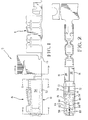
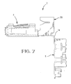
- the electrical terminal is shown generally at 2 including a front contacting section 4 and a wire terminating section 6.
- the inner contact section is shown as a box shaped receptacle at 8 having an overlying outer spring 10 (Figure 1) in surrounding relationship.
- the inner terminal includes a lower base section 12 which runs the substantial length of the terminal having a hinge section at 13 which carries the wire connection section 6.
- the wire connecting section 6 is shown as an insulation displacement type slot, although a wire terminating section such as an F-crimp or similar connection could also be incorporated.
- Two side walls 14 and 16 upstanding from the base portion 12, as best shown in Figure 5.
- a top wall portion 18 extends from the side wall portion 16 and is bent at a right angle relative to the side wall portion to form a substantially closed box.
- Each of the wall portions 12, and 14-18 extend forwardly and are constricted at 20 to form contact sections 22-28 respectively.
- a wire receiving slot section is shown at 30 which is profiled to receive a suppression device in the slot 32.
- This section 30 is profiled by upstanding wall sections 34 and 36 extending upwardly integral with respective wall sections 14 and 16.
- This section 30 also includes top cover portions 38 and 40, extending from respective extended wall portions 34 and 36 as best shown in Figures 2 and 6.
- lead-in openings 48 for the slots 32 are located along the front edges 42 and 44 of respective wall portions 34 and 36.
- the outer spring 10 comprises a lower base portion at 52 which lies substantially adjacent to lower base 12 of the inner contact portion and has side wall portions 54 and 56 which lie substantially adjacent to respective side wall portions 14 and 16 of the inner contact.
- the outer spring member 10 further includes top wall portions 58 and 60 ( Figure 2) adjacent to the front end of the terminal which are folded over to lie substantially adjacent to the top wall portion 18 of the inner contact.
- These top wall cover portions 58 and 60 include integral tabs 62 and 64 which extend from longitudinal seams 66 and 68, respectively. These tab portions 62 and 64 extend upwardly as shown in Figures 1 and 4 and are either welded or soldered together to fix the top wall portions 58 and 60 to hold them in a closed condition.
- the outer spring member 10 further includes rear top wall portions 70 and 72 which further include upstanding tab portions at 74 and 76.
- the top wall sections 78 and 80 which are intermediate the top wall portions 58, 70; 60 and 72 respectively are separated from the side walls and along a rear edge thereby forming two discrete rearwardly facing locking lances, as best shown in Figures 2 and 5.
- the tab portions 62 and 64 define a central polarizing rib where the locking lances 78 and 80 are positioned on opposite sides of the rib.
- the outer spring is also held to the contact member by way of tab portions 90 and 92 being clinched to the side walls 14 and 16 over an edge 94 formed in an opening 96 ( Figure 3).
- the terminal 2 is rotatable about the hinge web 14, to position the terminal into a right angle configuration.
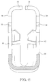
- the airbag connector is shown generally at 100 having a cover 102 where the connector 100 is generally comprised of an insulating housing 104, a plurality of the electrical terminals 2, a suppression device at 106, such as a resistor or capacitor, and electrical cable at 108.
- the terminal 2 can be positioned in the housing 104 with the front mating portion 4 positioned in a front cavity section 110 of the housing, having a pin receiving opening 112 leading into the contact section 4.
- the housing 104 also includes a nest at 116 for receiving the suppression device 106.
- the device 106 includes electrical leads 118a, 118b which are electrically connected to the slots 32 on two of the electrical terminals 2.
- the housing 104 further includes wire locating slots 119a, 119b for locating the leads 118a, 118b of the suppression device 106, as shown in Figure 9.
- the housing 104 includes a rear section 113 which can receive the box shaped section 130, which is in communication with the slots 119a and 119b.
- a housing portion 120 extends from one side of the housing 104 for receiving the wire connecting sections 6 of the electrical terminals 2.
- the housing is somewhat T-shaped in a cross section having oppositely directed parallel arm portions 117 and 120, and a perpendicular section 110.
- the cover 102 has an upper cover plate at 124 and latching arms such as 126, 128, and retention arms at 130 for maintaining the suppression device in place, having a circular surface 132 for engaging against the cylindrical suppression device 106.
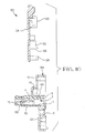
- an igniter for an airbag is shown generally at 140 which includes pin terminals at 142.
- a mating housing portion is shown at 150 including an outer shroud 152 for receiving the connector housing 104 and includes apertures at 154 for mating with latching arms 156 ( Figure 9) on the main housing.
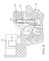
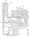
- the housing 150 includes a cavity at 160 for holding a shunt spring 162 where the shunt spring 162 includes a base portion 164, a contact arm 166 having a cantilever spring beam 168 for contact against the pins 142 when in the unmated condition.
- the housing 150 further includes a cavity 170 for receiving the connector 100, and as shown in Figure 12 the connector 100 begins to mate with the housing portion 150, but where the shunt member 162 is still in engagement with the pin portions 142. It should be noted that a front edge 165 of the housing engages the cantilever spring portion 168 in Figure 10, and as shown in Figure 13 has moved the shunt spring away from the pin terminals 142 when in the fully mated condition. When in the fully mated condition, the latch arms 156 carrying latching elements 157 towards the ends, are positioned in the apertures 154 ( Figure 11 maintaining the two in a fully mated condition).
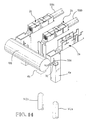
- the electrical connector 100 includes three terminals 2a, 2b, and 2c where the suppression device 106 has a lead 118a terminated to the slot 32 of terminal 2a.
- the opposite lead 118c is terminated to the slot 32 of the terminal 2c.
- the terminal 2a is not terminated to a lead, such as 108b or 108c, whereas the terminal 2c has no mating contact section.
- the serial signal connection is from pin 142a to contact 4a, through the suppression device 106, to the lead 108c, to the lead 108b, and back to the igniter pin 142b.
- the suppression device may be positioned within the corresponding nest 116 with the leads 118a, 118b in the corresponding slots 119a, 119b, and the terminals 2 can be pushed into their housing 104, such that the leads are then terminated in the corresponding slots 32.
- the suppression device 106 With the cover 102 in place, the suppression device 106 is held in place by the members 130 on the cover 102, while the leads are held in their corresponding slots 32 by a projection 113 on the housing 104.
Landscapes
- Engineering & Computer Science (AREA)
- Microelectronics & Electronic Packaging (AREA)
- Details Of Connecting Devices For Male And Female Coupling (AREA)
- Air Bags (AREA)
Claims (9)
- Assemblage de connecteur électrique comprenant un connecteur électrique (100), comportant un dispositif de suppression (106), connecté électriquement entre une paire de bornes (2a, 2c) dans un boítier (104), ledit boítier (104) comportant une section de réception (116) du dispositif de suppression (106), ledit dispositif de suppression (106) comportant une paire de conducteurs (118a, 118b), s'étendant à partir de celui-ci, caractérisé en ce que les bornes électriques (2a, 2c) connectant les conducteurs (118a, 118b) dudit dispositif de suppression (106) comportent:une section de contact (4), destinée à s'engager dans une borne (142a, 142b) d'un dispositif d'accouplement,une section de terminaison de fil (6), destinée à s'engager électriquement dans un fil conducteur (108c, 108b), etune fente de réception des fils (32), où sont connectés les conducteurs (118a, 118b) du dispositif de suppression (106),et en ce que une troisième borne (2b) fait partie du connecteur et comporte une section de contact (4b) et une section de terminaison de fil (6), un fil conducteur (108b, 108c) étant connecté électriquement à ladite troisième borne (2b), un autre fil conducteur (108b, 108c) étant connecté électriquement à l'une (2c) des première et deuxième bornes (2a, 2c), une première borne (142b) dudit dispositif d'accouplement étant connectée à la section de contact (4b) de la troisième borne (2b), et une deuxième borne (142a) dudit dispositif d'accouplement étant connectée à la section de contact (4a) de l'autre (2a) desdites première et deuxième bornes (2a, 2c).
- Assemblage de connecteur électrique selon la revendication 1, caractérisé en ce que la fente de réception des fils (32) est positionnée entre ladite section de contact (4) et ladite section de terminaison de fil (6).
- Assemblage de connecteur électrique selon les revendications 1 ou 2, caractérisé en ce que les bornes (2) sont agencées à angle droit et sont repliées derrière la fente de réception de fils additionnelle (32).
- Assemblage de connecteur électrique selon l'une quelconque des revendications précédentes, caractérisé en ce que la fente de réception des fils additionnelle (32) est agencée dans une section en forme de boíte (30) de la borne, à l'arrière de la section de contact avant (4).
- Assemblage de connecteur électrique selon la revendication 3, caractérisé en ce que ledit boítier (104) a une section transversale en forme de T et est composée d'éléments de bras (117, 120) avec un élément perpendiculaire (110), les passage de réception des bornes (112) étant agencés dans l'élément perpendiculaire (110).
- Assemblage de connecteur électrique selon la revendication 5, caractérisé en ce que la section de terminaison de fil (6) est agencée à angle droit derrière ladite fente de réception des fils additionnelle (32), lesdites sections de terminaison des fils (6) étant agencées sur une base de l'un desdits éléments de bras (120).
- Assemblage de connecteur électrique selon l'une quelconque des revendications précédentes, caractérisé en ce que l'élément de bras opposé (117) du boítier (104) englobe un logement de réception (116) d'un dispositif de suppression.
- Assemblage de connecteur électrique comprenant un connecteur électrique (100), comportant un dispositif de suppression (106), connecté électriquement entre une paire de bornes (2a, 2c) dans un boítier (104), ledit boítier (104) comportant une section de réception (116) du dispositif de suppression (106) et ledit dispositif de suppression (106) comportant une paire de conducteurs (118a, 118b) s'étendant à partir de celui-ci, le connecteur (100) étant caractérisé par:une première borne électrique (2a) comportant une section de contact (4a), destinée à s'engager dans une borne (142a) du dispositif d'accouplement, et une fente de réception de fils (32), destinée à s'engager électriquement dans l'un des conducteurs (118a) du dispositif de suppression (106),une deuxième borne électrique (2b) comportant une section de terminaison de fil destinée à s'engager dans un fil conducteur (108c) et une section de contact (4b), destinée à s'engager dans une borne additionnelle (142c) d'un dispositif d'accouplement, etune troisième borne électrique (2c) comportant une section de terminaison de fil, destinée à s'engager dans un fil conducteur additionnel (108c) et une fente de réception de fils, destinée à s'engager électriquement dans l'autre des conducteurs (118a) du dispositif de suppression (106), un fil conducteur (108c, 108b) étant connecté électriquement à ladite troisième borne (2c), un autre fil conducteur (108c, 108b) étant connecté électriquement à ladite deuxième borne (2b), une première borne (142b) dudit dispositif d'accouplement pouvant être connectée à la section de contact (4b) de la deuxième borne (2b), et une deuxième borne (142a) dudit dispositif d'accouplement pouvant être connectée à la section de contact (4a) de l'autre (2a) desdites première et deuxième bornes (2a, 2b).
- Assemblage de connecteur électrique comprenant un connecteur électrique (100) pour une connexion en série de signaux et comportant un dispositif de suppression (106), connecté électriquement entre une paire de bornes (2) dans un boítier (104), ledit boítier (104) comportant une section de réception (116) du dispositif de suppression (106), ledit dispositif de suppression (106) comportant une paire de conducteurs (118a, 118b), s'étendant à partir de celui-ci, le connecteur (100) étant caractérisé en ce que les bornes électriques (2a, 2c) connectant les conducteurs (118a, 118b) dudit dispositif de suppression (106) comportent:caractérisé en outre en ce qu'il comporte une troisième borne électrique (2b) avec une section de contact (4b) et une section de terminaison de fil, la connexion en série de signaux passant de la première borne (142a) du dispositif d'accouplement vers la section de contact (4a) de la première borne électrique (2a), à travers le dispositif de suppression (106) vers la deuxième borne (2c) et vers un premier des fils conducteurs (108c), vers un deuxième des fils conducteurs (108b), vers la troisième borne (2b) et vers la deuxième borne (142b) du dispositif d'accouplement.une section de contact (4a), destinée à s'engager dans une borne (142a, 142b) d'un dispositif d'accouplement,une section de terminaison de fil (6), destinée à s'engager électriquement dans un fil conducteur (108c, 108b), etune fente de réception des fils additionnelle (32) où sont connectés les conducteurs (118a, 118b) du dispositif de suppression (106),
Applications Claiming Priority (2)
| Application Number | Priority Date | Filing Date | Title |
|---|---|---|---|
| GB9225118 | 1992-12-01 | ||
| GB929225118A GB9225118D0 (en) | 1992-12-01 | 1992-12-01 | Shunted airbag connector |
Publications (2)
| Publication Number | Publication Date |
|---|---|
| EP0600418A1 EP0600418A1 (fr) | 1994-06-08 |
| EP0600418B1 true EP0600418B1 (fr) | 1998-03-04 |
Family
ID=10725947
Family Applications (1)
| Application Number | Title | Priority Date | Filing Date |
|---|---|---|---|
| EP93119221A Expired - Lifetime EP0600418B1 (fr) | 1992-12-01 | 1993-11-29 | Connecteur électrique ayant un dispositif de suppression |
Country Status (4)
| Country | Link |
|---|---|
| US (1) | US5435754A (fr) |
| EP (1) | EP0600418B1 (fr) |
| DE (1) | DE69317219T2 (fr) |
| GB (1) | GB9225118D0 (fr) |
Cited By (2)
| Publication number | Priority date | Publication date | Assignee | Title |
|---|---|---|---|---|
| DE102005007066B3 (de) * | 2005-02-16 | 2006-10-05 | Tyco Electronics Amp Gmbh | Miniaturisierte elektrische Steckereinheit mit verbesserter Crimpbarkeit |
| DE102005043903B3 (de) * | 2005-09-14 | 2007-03-01 | Tyco Electronics Amp Gmbh | Stecker |
Families Citing this family (38)
| Publication number | Priority date | Publication date | Assignee | Title |
|---|---|---|---|---|
| DE9314667U1 (de) * | 1993-09-28 | 1994-03-17 | Siemens AG, 80333 München | Steckverbinder-Kupplung |
| DE4339347C2 (de) * | 1993-11-18 | 2002-06-27 | Takata Petri Ag | Stecker für Gasgeneratoren von Gassack-Aufprall-Schutzeinrichtungen |
| GB9417215D0 (en) * | 1994-08-25 | 1994-10-12 | Amp Great Britain | Electrical harness having an ectrical connector with an electrical component therin and a method of making |
| US5685743A (en) * | 1994-11-07 | 1997-11-11 | Grote & Hartmann Gmbh & Co. Kg | Connector housing for an air bag connector and a method for contacting a connector housing |
| JPH08163813A (ja) * | 1994-12-07 | 1996-06-21 | Sumitomo Wiring Syst Ltd | コネクタ |
| JPH08163812A (ja) * | 1994-12-07 | 1996-06-21 | Sumitomo Wiring Syst Ltd | 電気接続構造 |
| GB9500782D0 (en) * | 1995-01-16 | 1995-03-08 | Amp Gmbh | Insulation displacement contact for multiple wire sizes |
| JP3579130B2 (ja) * | 1995-06-21 | 2004-10-20 | タイコエレクトロニクスアンプ株式会社 | 電気コネクタ |
| US5616045A (en) * | 1995-07-14 | 1997-04-01 | Augat Inc. | Squib connector for automotive air bag assembly |
| DE19531126C1 (de) * | 1995-08-24 | 1996-12-12 | Delphi Automotive Systems Gmbh | Verfahren zur Herstellung eines elektrischen Verbinders |
| US5609498A (en) * | 1995-09-19 | 1997-03-11 | Itt Corporation | Secure connector system |
| JP3315313B2 (ja) * | 1996-05-17 | 2002-08-19 | 矢崎総業株式会社 | コネクタ構造 |
| WO1998009486A1 (fr) * | 1996-08-27 | 1998-03-05 | Siemens Aktiengesellschaft | Dispositif pourvu d'un circuit electrique pour commander les moyens de retenue dans un vehicule |
| US5882224A (en) * | 1996-08-28 | 1999-03-16 | Thomas & Betts International, Inc. | Squib connector socker assembly having shorting clip for automotive air bags |
| JPH1092541A (ja) * | 1996-09-13 | 1998-04-10 | Furukawa Electric Co Ltd:The | 回転コネクタ |
| AU5241698A (en) * | 1996-10-29 | 1998-05-22 | Whitaker Corporation, The | Contact with latch for contact retention and housing therefor |
| DE19648710C1 (de) * | 1996-11-25 | 1998-02-19 | Bosch Gmbh Robert | Vielpoliger Steckverbinder |
| DE19712314A1 (de) * | 1997-03-24 | 1998-10-01 | Thomas & Betts Gmbh | Verbindung für die Zündeinrichtung von Airbag-Systemen in Kraftfahrzeugen |
| US6220890B1 (en) | 1999-03-25 | 2001-04-24 | Illinois Tool Works Inc. | Electrical switch connector assembly |
| US6139345A (en) * | 1999-10-18 | 2000-10-31 | Itt Manufacturing Enterprises, Inc. | Clip for coupling component to connector contacts |
| US6398590B2 (en) | 2000-07-11 | 2002-06-04 | Tyco Electronics Corporation | Nonpolarized electrical connector assembly especially for use as automotive squib connector |
| TW504054U (en) * | 2000-12-30 | 2002-09-21 | Hon Hai Prec Ind Co Ltd | Electrical connector |
| JP2003249308A (ja) * | 2002-02-25 | 2003-09-05 | Tyco Electronics Amp Kk | 電気コネクタ組立体 |
| US20040043652A1 (en) * | 2002-08-30 | 2004-03-04 | Special Devices, Inc. | Initiator having integral features for orienting and holding an insertable electrical shunt |
| US6997750B2 (en) | 2003-07-23 | 2006-02-14 | Fci Americas Technology, Inc. | Electrical connector contact |
| JP2005251395A (ja) * | 2004-03-01 | 2005-09-15 | Jst Mfg Co Ltd | 電気的接続装置 |
| JP4473042B2 (ja) | 2004-05-26 | 2010-06-02 | 株式会社ジェイテクト | トルク検出装置、ワイヤーハーネス、電動パワーステアリング装置及び端子ホルダ |
| US7307495B2 (en) * | 2004-06-17 | 2007-12-11 | Fci Americas Technology, Inc. | Electrical filter assembly having IDC connection |
| US7162388B2 (en) * | 2004-06-17 | 2007-01-09 | Fci Americas Technology, Inc. | Vehicle air bag electrical system |
| DE202005021651U1 (de) * | 2005-02-02 | 2009-02-19 | Amphenol-Tuchel Electronics Gmbh | Stecker mit Störschutzvorrichtung für Leitungssätze |
| US7645151B2 (en) * | 2007-03-22 | 2010-01-12 | Tyco Electronics Corporation | Shunted electrical connector and shunt therefore |
| DE102007059932B3 (de) * | 2007-12-12 | 2009-07-09 | Tyco Electronics Amp Gmbh | Unterbrecher für eine elektrische Leitung |
| ES2389887T3 (es) * | 2008-09-10 | 2012-11-02 | Fci Automotive Holding | Contacto eléctrico , conjunto de contacto eléctrico, producto y conjunto que comprenden dicho contacto eléctrico, su procedimiento de fabricación y procedimiento de conexión eléctrica |
| US8202124B1 (en) * | 2011-03-11 | 2012-06-19 | Lear Corporation | Contact and receptacle assembly for a vehicle charging inlet |
| US10615547B2 (en) * | 2016-09-08 | 2020-04-07 | Raytheon Company | Electrical device with shunt, and receptacle |
| JP7014139B2 (ja) * | 2018-11-27 | 2022-02-01 | 住友電装株式会社 | コネクタ |
| CN110277691B (zh) * | 2019-06-22 | 2020-12-25 | 阜阳正林新能源科技有限公司 | 一种电源接线端子 |
| FR3102314B1 (fr) | 2019-10-22 | 2023-05-12 | Aptiv Tech Ltd | Ensemble de connexion pour dispositif de sécurité passive, protégé contre les décharges électrostatiques |
Family Cites Families (16)
| Publication number | Priority date | Publication date | Assignee | Title |
|---|---|---|---|---|
| US3636495A (en) * | 1970-04-09 | 1972-01-18 | Jack A Frost | Floor plug |
| US4113340A (en) * | 1977-06-27 | 1978-09-12 | Illinois Tool Works Inc. | Protective electrical device |
| US4116524A (en) * | 1977-06-29 | 1978-09-26 | Illinois Tool Works | Terminal bridging assembly |
| US4113341A (en) * | 1977-08-12 | 1978-09-12 | Amp Incorporated | Electrical connector having provision for circuit components |
| US4447105A (en) * | 1982-05-10 | 1984-05-08 | Illinois Tool Works Inc. | Terminal bridging adapter |
| US4778405A (en) * | 1984-10-05 | 1988-10-18 | Amp Incorporated | T-tap electrical connector having opening for test probe |
| US4679885A (en) * | 1986-08-01 | 1987-07-14 | General Motors Corporation | Electrical component packaging assembly |
| DE3814016A1 (de) * | 1988-04-26 | 1989-11-09 | Telefonbau & Normalzeit Gmbh | Stecker mit elektrischen bauelementen |
| US4952169A (en) * | 1989-06-27 | 1990-08-28 | Amp Incorporated | Sealed electrical connector employing insulation displacement terminals |
| CH681873A5 (fr) * | 1990-04-09 | 1993-06-15 | Bobst Sa | |
| DE59108070D1 (de) * | 1990-09-28 | 1996-09-19 | Siemens Ag | Kontaktbauelement |
| GB2250645B (en) * | 1990-12-06 | 1994-10-12 | Amp Inc | An electrical connector and an electrical terminal therefor |
| GB9103902D0 (en) * | 1991-02-25 | 1991-04-10 | Raychem Sa Nv | Electrically-protected connector |
| DE4217205C2 (de) * | 1992-05-23 | 1994-09-08 | Amphenol Tuchel Elect | Steckverbinder |
| US5288242A (en) * | 1992-07-20 | 1994-02-22 | Itt Corporation | Ring lock connector |
| US5314345A (en) * | 1992-10-09 | 1994-05-24 | Trw Inc. | Electrical connection system with interlock |
-
1992
- 1992-12-01 GB GB929225118A patent/GB9225118D0/en active Pending
-
1993
- 1993-11-29 EP EP93119221A patent/EP0600418B1/fr not_active Expired - Lifetime
- 1993-11-29 DE DE69317219T patent/DE69317219T2/de not_active Expired - Fee Related
-
1994
- 1994-11-09 US US08/336,885 patent/US5435754A/en not_active Expired - Fee Related
Cited By (3)
| Publication number | Priority date | Publication date | Assignee | Title |
|---|---|---|---|---|
| DE102005007066B3 (de) * | 2005-02-16 | 2006-10-05 | Tyco Electronics Amp Gmbh | Miniaturisierte elektrische Steckereinheit mit verbesserter Crimpbarkeit |
| US7125284B2 (en) | 2005-02-16 | 2006-10-24 | Tyco Electronics Amp Gmbh | Miniaturized electrical connector with improved crimpability |
| DE102005043903B3 (de) * | 2005-09-14 | 2007-03-01 | Tyco Electronics Amp Gmbh | Stecker |
Also Published As
| Publication number | Publication date |
|---|---|
| DE69317219D1 (de) | 1998-04-09 |
| GB9225118D0 (en) | 1993-01-20 |
| DE69317219T2 (de) | 1998-08-06 |
| EP0600418A1 (fr) | 1994-06-08 |
| US5435754A (en) | 1995-07-25 |
Similar Documents
| Publication | Publication Date | Title |
|---|---|---|
| US5435754A (en) | Shunted airbag connector | |
| US5096442A (en) | Compact electrical connector | |
| EP0600419B1 (fr) | Douille terminale électrique | |
| US4451099A (en) | Electrical connector having commoning member | |
| US4428636A (en) | Multi-contact connectors for closely spaced conductors | |
| KR970004154B1 (ko) | 차폐 모듈 잭 | |
| US5310362A (en) | Pin-and-socket connector | |
| US4341428A (en) | Interconnection system for shielded electrical cable | |
| US5913690A (en) | Electrical grounding shroud | |
| US5908322A (en) | Joint connector | |
| US4491381A (en) | Electrical panelboard connector | |
| US4345813A (en) | Keyable connector-header assemblies for multiple conductor cables | |
| US20040102097A1 (en) | Telecommunications jack assembly | |
| EP1009070B1 (fr) | Connecteur électrique filtré avec multiples éléments de ferrite | |
| US5286222A (en) | Shielded floating electric connector | |
| US4732568A (en) | Electrical connector with integral ground strap for shielded cable | |
| US5611711A (en) | Electrical connector assembly | |
| US6488520B1 (en) | Electrical connector assembly with shorting members | |
| US6299476B1 (en) | Electrical connector with a flexible circuit and rigidizer subassembly and a spring | |
| US3958852A (en) | Electrical connector | |
| GB2276283A (en) | Electrical connector with short-circuiting facility | |
| US4874333A (en) | Shunted modular electrical connector | |
| US4737888A (en) | Receptacle assembly and mounting bracket for circuit board connections | |
| US4738638A (en) | Electrical connector with improved integral ground strap for shielded cable | |
| EP1166400B1 (fr) | Connecteur electrique |
Legal Events
| Date | Code | Title | Description |
|---|---|---|---|
| PUAI | Public reference made under article 153(3) epc to a published international application that has entered the european phase |
Free format text: ORIGINAL CODE: 0009012 |
|
| AK | Designated contracting states |
Kind code of ref document: A1 Designated state(s): DE FR GB IT |
|
| 17P | Request for examination filed |
Effective date: 19941207 |
|
| 17Q | First examination report despatched |
Effective date: 19960418 |
|
| GRAG | Despatch of communication of intention to grant |
Free format text: ORIGINAL CODE: EPIDOS AGRA |
|
| GRAG | Despatch of communication of intention to grant |
Free format text: ORIGINAL CODE: EPIDOS AGRA |
|
| GRAG | Despatch of communication of intention to grant |
Free format text: ORIGINAL CODE: EPIDOS AGRA |
|
| GRAH | Despatch of communication of intention to grant a patent |
Free format text: ORIGINAL CODE: EPIDOS IGRA |
|
| GRAH | Despatch of communication of intention to grant a patent |
Free format text: ORIGINAL CODE: EPIDOS IGRA |
|
| GRAA | (expected) grant |
Free format text: ORIGINAL CODE: 0009210 |
|
| AK | Designated contracting states |
Kind code of ref document: B1 Designated state(s): DE FR GB IT |
|
| PG25 | Lapsed in a contracting state [announced via postgrant information from national office to epo] |
Ref country code: IT Free format text: LAPSE BECAUSE OF FAILURE TO SUBMIT A TRANSLATION OF THE DESCRIPTION OR TO PAY THE FEE WITHIN THE PRESCRIBED TIME-LIMIT;WARNING: LAPSES OF ITALIAN PATENTS WITH EFFECTIVE DATE BEFORE 2007 MAY HAVE OCCURRED AT ANY TIME BEFORE 2007. THE CORRECT EFFECTIVE DATE MAY BE DIFFERENT FROM THE ONE RECORDED. Effective date: 19980304 |
|
| REF | Corresponds to: |
Ref document number: 69317219 Country of ref document: DE Date of ref document: 19980409 |
|
| ET | Fr: translation filed | ||
| PLBE | No opposition filed within time limit |
Free format text: ORIGINAL CODE: 0009261 |
|
| STAA | Information on the status of an ep patent application or granted ep patent |
Free format text: STATUS: NO OPPOSITION FILED WITHIN TIME LIMIT |
|
| 26N | No opposition filed | ||
| REG | Reference to a national code |
Ref country code: GB Ref legal event code: IF02 |
|
| PGFP | Annual fee paid to national office [announced via postgrant information from national office to epo] |
Ref country code: GB Payment date: 20041004 Year of fee payment: 12 |
|
| PGFP | Annual fee paid to national office [announced via postgrant information from national office to epo] |
Ref country code: FR Payment date: 20041105 Year of fee payment: 12 |
|
| PG25 | Lapsed in a contracting state [announced via postgrant information from national office to epo] |
Ref country code: GB Free format text: LAPSE BECAUSE OF NON-PAYMENT OF DUE FEES Effective date: 20051129 |
|
| GBPC | Gb: european patent ceased through non-payment of renewal fee |
Effective date: 20051129 |
|
| PG25 | Lapsed in a contracting state [announced via postgrant information from national office to epo] |
Ref country code: FR Free format text: LAPSE BECAUSE OF NON-PAYMENT OF DUE FEES Effective date: 20060731 |
|
| REG | Reference to a national code |
Ref country code: FR Ref legal event code: ST Effective date: 20060731 |
|
| PGFP | Annual fee paid to national office [announced via postgrant information from national office to epo] |
Ref country code: DE Payment date: 20070102 Year of fee payment: 14 |
|
| PG25 | Lapsed in a contracting state [announced via postgrant information from national office to epo] |
Ref country code: DE Free format text: LAPSE BECAUSE OF NON-PAYMENT OF DUE FEES Effective date: 20080603 |