EP0600547A1 - Système de transmission en diversité par sous-bandes - Google Patents
Système de transmission en diversité par sous-bandes Download PDFInfo
- Publication number
- EP0600547A1 EP0600547A1 EP93203310A EP93203310A EP0600547A1 EP 0600547 A1 EP0600547 A1 EP 0600547A1 EP 93203310 A EP93203310 A EP 93203310A EP 93203310 A EP93203310 A EP 93203310A EP 0600547 A1 EP0600547 A1 EP 0600547A1
- Authority
- EP
- European Patent Office
- Prior art keywords
- sub
- band
- signal
- signals
- combining
- Prior art date
- Legal status (The legal status is an assumption and is not a legal conclusion. Google has not performed a legal analysis and makes no representation as to the accuracy of the status listed.)
- Granted
Links
Images


Classifications
-
- H—ELECTRICITY
- H04—ELECTRIC COMMUNICATION TECHNIQUE
- H04L—TRANSMISSION OF DIGITAL INFORMATION, e.g. TELEGRAPHIC COMMUNICATION
- H04L1/00—Arrangements for detecting or preventing errors in the information received
- H04L1/02—Arrangements for detecting or preventing errors in the information received by diversity reception
- H04L1/06—Arrangements for detecting or preventing errors in the information received by diversity reception using space diversity
-
- H—ELECTRICITY
- H04—ELECTRIC COMMUNICATION TECHNIQUE
- H04B—TRANSMISSION
- H04B7/00—Radio transmission systems, i.e. using radiation field
- H04B7/02—Diversity systems; Multi-antenna system, i.e. transmission or reception using multiple antennas
- H04B7/04—Diversity systems; Multi-antenna system, i.e. transmission or reception using multiple antennas using two or more spaced independent antennas
- H04B7/08—Diversity systems; Multi-antenna system, i.e. transmission or reception using multiple antennas using two or more spaced independent antennas at the receiving station
- H04B7/0837—Diversity systems; Multi-antenna system, i.e. transmission or reception using multiple antennas using two or more spaced independent antennas at the receiving station using pre-detection combining
- H04B7/0842—Weighted combining
- H04B7/0865—Independent weighting, i.e. weights based on own antenna reception parameters
-
- H—ELECTRICITY
- H04—ELECTRIC COMMUNICATION TECHNIQUE
- H04L—TRANSMISSION OF DIGITAL INFORMATION, e.g. TELEGRAPHIC COMMUNICATION
- H04L27/00—Modulated-carrier systems
- H04L27/26—Systems using multi-frequency codes
- H04L27/2601—Multicarrier modulation systems
- H04L27/2647—Arrangements specific to the receiver only
-
- H—ELECTRICITY
- H04—ELECTRIC COMMUNICATION TECHNIQUE
- H04B—TRANSMISSION
- H04B7/00—Radio transmission systems, i.e. using radiation field
- H04B7/02—Diversity systems; Multi-antenna system, i.e. transmission or reception using multiple antennas
- H04B7/04—Diversity systems; Multi-antenna system, i.e. transmission or reception using multiple antennas using two or more spaced independent antennas
- H04B7/08—Diversity systems; Multi-antenna system, i.e. transmission or reception using multiple antennas using two or more spaced independent antennas at the receiving station
- H04B7/0837—Diversity systems; Multi-antenna system, i.e. transmission or reception using multiple antennas using two or more spaced independent antennas at the receiving station using pre-detection combining
- H04B7/084—Equal gain combining, only phase adjustments
Definitions
- the invention is related to a diversity transmission system comprising a transmitter, being coupled to a receiver via various channels, which receiver comprises combining means for combining the output signals of the channels.
- the invention is also related to a receiver for use in such a system.
- Diversity transmission systems are used for transmission of information via channels which can have various degrees of transmission quality, which even can be time dependent. To prevent a degraded transmission quality a number of such channels are used in parallel, and the output signals of such channels are combined. This combination can be performed in many ways, for example by simply adding the output signals of the channels, selecting the best channel or determining a weighted sum of the output signals of the channels. Also the weighting factor can be determined in various ways.
- the object of the invention is to provide a diversity transmission system according to the preamble having an improved performance when the quality of the transmission channels is unsatisfactory.
- the diversity transmission system is characterised in that the combining means comprise separating means for separating the output signal of each channel into a number of sub-band signals and in that the combining means comprises sub-band combining means for combining corresponding sub- band signals from different channels into combined sub-band signals.
- the invention is based on the insight that in certain circumstances the transmission quality of only a part of the total transmission frequency band is unsatisfactory, and that this part is different for different channels.
- An embodiment of the invention is characterised in that the receiver comprises a number of antennas at different positions for obtaining the output signal of a corresponding channel.
- each channel comprises the radio link between a transmitter and the corresponding antenna.
- a further embodiment of the invention is characterised in that the receiver comprises a number of antennas having different polarisation states for obtaining the output signal of a corresponding channel.
- the polarisation states can comprise different linear polarisation directions, but they can also comprise left hand or right hand rotating circular or elliptical polarisation. Also combinations of linear and circular/elliptical polarisation are conceivable.
- a further possibility is the use of antennas receiving signals from different directions.
- a further embodiment of the invention is characterised in that the output signal of a channel comprises a Frequency Division Multiplexed signal, and in that a sub-band comprises at least one component of the frequency division multiplexed signal.By choosing the sub-bands in correspondence to the frequency division multiplexed parts of the received signal, the separating means are simultaneously used for separating the received signals into sub-bands for the diversity reception, and for demultiplexing the received (frequency division multiplexed) signal.
- a further embodiment of the invention is characterised in that the output signal of a channel comprises an Orthogonally Frequency Division Multiplexed signal.
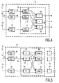
- an output of a signal source 2 is connected to an input of transmitters 4, 6 and 8.
- An output of the transmitter 4 is coupled to a first input of a receiver 16 via a channel 10.
- An output of the transmitter 6 is coupled to a second input of the receiver 16 via a channel 12 and an output of the transmitter 8 is coupled to a third input of the receiver 16 via a channel 14.
- a destination signal is available at the output of the receiver 16 .
- the source signal is transmitted via three separate channels 10,12 and 14 by means of the transmitters 4, 6 and 8.
- the receiver 16 derives from the three input signals the destination signal for further processing by combining the input signals in a suitable manner.
- a signal source 2 is coupled to a single transmitter 4 which is in turn coupled to a transmitting antenna 5.
- Three inputs of the receiver 16 are coupled to a corresponding receiving antenna 9, 11 or 13.
- the channel comprises now the three radio links 10, 11 and 12 between the common transmitting antenna and the different receiving antennas 9, 11 and 13. It is evident that the number of channels in the transmission systems according to Fig. 1 and 2 can have any arbitrary value N larger than one.
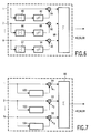
- the antennas 20, 22 ⁇ ⁇ ⁇ 24 can have different positions or different polarisation states, or a combination thereof.
- each input of the combining means is connected to separating means 34,36 ⁇ ⁇ ⁇ 38 for separating the broadband signal in a number of sub-band signals.
- Outputs of the separating means 34, 36 ⁇ ⁇ ⁇ 38 carrying sub-band signals in the same sub-band, are connected to inputs of sub-band combining means 40, 42 ⁇ ⁇ ⁇ 44.
- the number of sub-bands is assumed to have a value L.
- Outputs of the sub-band combining means 40, 42 ⁇ ⁇ ⁇ 44 are connected to final combining means to obtain a combined broad band signal, for example by simple adding. It is also possible to equalize the power of the output signals of the sub-band combining means before combining. This results in a flat frequency response of the combination of channels for the wide-band signals.
- the separating means 34, 36 ⁇ ⁇ ⁇ 38 can comprise a filter bank comprising L band pass filters having adjacent pass bands for obtaining the L sub-band signals.
- the diversity receiver according to Fig. 4 for reception of a PAL TV signal can be derived from the receiver according to Fig. 3 by replacing the filter banks 34, 36 ⁇ ⁇ ⁇ 38 by PAL demultiplexers 50, 52 ⁇ ⁇ ⁇ 54 and by omitting the final combining means 46.
- the PAL demultiplexers 50, 52 ⁇ ⁇ ⁇ 54 comprise three filters for separating the luminance signal, the chrominance signal and the sound signal from the IF signal applied to its input by the corresponding front end. For separating the luminance signal from the IF signal from the front end a band-pass having a band width of approximately 5 MHz can be used.
- a band pass filter having a band width of approximately 2 Mhz has to be used, and for separating the sound signal a band pass filter and bandwidth of 200-300 kHz is necessary.
- the centre frequency of these filters is determined by the frequency of the IF signal delivered by the front ends 26,28 ⁇ ⁇ ⁇ 30.
- the three components (sub-bands) of the video signal delivered by the different front ends 26, 28 ⁇ ⁇ ⁇ 30 are combined component wise by the sub-band combining means 56, 58 ⁇ ⁇ ⁇ 60 to combined sub-band signals, being a combined luminance signal, a combined chrominance signal and a combined sound signal. Further combination is not needed because these signals can be directly processed by a video display system.
- the receiver according to Fig. 5 for reception of digitally modulated OFDM signals can be derived from the receiver according to Fig. 3 by replacing the filter banks 34, 36 ⁇ ⁇ ⁇ 38 (separating means) by FFT (Fast Fourier Transform) units 62,64 ⁇ ⁇ ⁇ 66 and by introducing analog to digital conversion means into the front ends 26, 28 ⁇ ⁇ ⁇ 30.
- the final combining means 46 (Fig. 3) can be dispensed with.
- Orthogonal Frequency Division Multiplexing is a technique to combine many narrow-band signals into one wide-band signal using a Fast Fourier Transform (FFT).
- FFT Fast Fourier Transform
- a suitable OFDM signal for TV transmission has a band width of 8.192 MHz , containing 1024 subchannels each having a band width of 8 kHz.
- OFDM is very well suited for transmission over multipath fading channels as the terrestrial VHF/UHF channel. Due to multipath reception, the multipath fading channels have the property of frequency selectivity.
- the information in each subchannel will display a different effective signal-to-noise ratio.
- the minimum frequency between narrow-band signals with mutually independent signal-to-noise ratio's is called the coherence bandwidth B c . From measurements with indoor reception, it appears that the fading characteristics in the frequency domain heavily depend of the location of the receiving antenna (spatial fading). Due to this dependence the invention can advantageously be used in combination with OFDM and spatial antenna diversity.
- Each of the front ends 26,28 ⁇ ⁇ ⁇ 30 deliver a digital signal to its corresponding FFT unit 62,64 ⁇ ⁇ ⁇ 66.
- the FFT units 62,64 ⁇ ⁇ ⁇ 66 calculate a 1024 points FFT from 1024 consecutive samples of the output signals of the front end.
- the calculation of an FFT is functionally equivalent to splitting the input signal into 1024 sub-bands.
- Corresponding sub-bands from different FFT units are combined by the sub-band combining means 62,64 ⁇ ⁇ ⁇ 66 to a combined sub-band signal.
- the combined sub-band signals are available for further processing.
- the output signals of the front-ends 26,28 ⁇ ⁇ ⁇ 30 are splitted in less than 1024 sub-bands, for example 64 sub-bands. After combination to combined sub-band signals by the sub-band combining means, these sub-band signals have to be separated by the sub-band separating means 74,76 ⁇ ⁇ ⁇ 78 into 16 separate signals, to obtain the 1024 subchannels.
- a suitable way of combining the sub-band channels is to select one of these channels, by means of a selection switch.
- This switch can be controlled to select the sub-band having the largest power. It is also possible to control the selection switch according to a measured symbol error rate and to choose the sub-band which results in the smallest symbol error rate.
- Another possibility is the use of a second selection switch in addition to the first selection switch which scans the sub-bands periodically. Then the first selection switch is set to the position of the second selection switch which gives the best reception quality.
- the N sub-band signals to be combined are applied to a first input of a corresponding multiplier 84, 90 ⁇ ⁇ ⁇ 96, and to an input of means 80,86 ⁇ ⁇ ⁇ 92 for determining the modulus of the sub-band signal.
- the output of the means 80 (86) [92] is connected to an input of a low pass filter 82 (88) [94].
- the output of the low pass filter 82 (88) [94] is connected to a second input of the multiplier 84 (94) [96].
- the output of the multipliers 84,90 ⁇ ⁇ ⁇ 96 are connected to inputs of an adder 98. At the output of the adder the combined sub-band signal is available.
- r i ⁇ i ⁇ S +n i (1)
- r i is the i th sub-band signal of N sub-band signals to be combined
- ⁇ i is the complex attenuation factor of the i th channel of the transmission system
- n i the noise in the i th sub-band channel
- S is the signal to be transmitted in the sub-band.
- the combiner according to Fig. 6 determines the value: The most favourable situation occurs when the argument of all values ⁇ i is the same. Then (2) can be written as: In which ⁇ is the argument of ⁇ i .
- the sub-band combining means according to Fig. 7 can be derived from that according to Fig. 6 by replacing the combination of the means for determining the modulus of the sub-band signal and the low pass filter by a channel state estimator which makes an estimation of the complex attenuation factor of a sub-band in a certain channel.
- the multipliers 84,90 ⁇ ⁇ ⁇ 96 are used for multiplying the sub-band signal with the complex conjugate of the estimate of the complex attenuation factor of the sub-band.
- ⁇ can be done in various ways known in the art.
- digital signals use can be made of the vast amount of methods for determining the transfer functions of a channel used in adaptive pass band equalisation. A number of these methods are for example described in the book “Digital Communication” by Lee and Messerschmitt, 1990 , ISBN 0-89838-274-2, Chapter 9.5, pp. 309-402.
- a method which can also be used for analog signals is disclosed in the book “Microwave Mobile Communications", By Jakes, 1974, Wiley, Chapter 6.3, Fig. 6.3-3.
- the only modification that has to be performed is the omitting of the limiting operation described at page 426, however it is also possible to obtain a usefull combining operation when the limiting operation is used .
- the channel state estimator is replaced by a delay element having a delay time T.
- This type of sub-band combining means can be used for differential coded digital transmission.
- r ij S j ⁇ i +n ij (9)
- r i,j is the input signal at the i th input of the sub-band combining means at instant jT
- S j is the transmitted signal at instant jT
- n i,j is the noise signal at the i th input of the sub-band combining means at instant jT.
- the output signal of the i th multiplier can be derived: At a large signal to noise ratio the cross product of the noise terms can be neglected.
- the output signal of the sub-band combining means 40 can be written: Assuming differential coding at the transmitter, for example Differential Phase Shift Keying, and assuming statistical independence of the noise signals, leads to the following expression for the signal to noise ratio: From (12) can be seen that always a near optimal (3dB loss) combining of the sub-band signals is obtained, without the need of a carrier recovery system as was needed for the sub band combining means 40 according to Fig. 7.
- Fig. 9a and Fig. 9b show plots of the power spectrum of an (originally white) OFDM signal, having a carrier frequency of 762 MHz and a bandwidth of 3.5 MHz, received in a building from a transmitter outside the building. These two power spectra were measured at two receiving antenna positions at a distance of 1 meter. It can be seen that the location of fades is strongly dependent of the antenna position. From these figures also can be seen that it is possible to obtain a signal without fades by using the combining technique according to the invention.
Landscapes
- Engineering & Computer Science (AREA)
- Computer Networks & Wireless Communication (AREA)
- Signal Processing (AREA)
- Radio Transmission System (AREA)
Priority Applications (1)
| Application Number | Priority Date | Filing Date | Title |
|---|---|---|---|
| EP93203310A EP0600547B1 (fr) | 1992-12-01 | 1993-11-26 | Système de transmission en diversité par sous-bandes |
Applications Claiming Priority (3)
| Application Number | Priority Date | Filing Date | Title |
|---|---|---|---|
| EP92120487 | 1992-12-01 | ||
| EP92120487 | 1992-12-01 | ||
| EP93203310A EP0600547B1 (fr) | 1992-12-01 | 1993-11-26 | Système de transmission en diversité par sous-bandes |
Publications (2)
| Publication Number | Publication Date |
|---|---|
| EP0600547A1 true EP0600547A1 (fr) | 1994-06-08 |
| EP0600547B1 EP0600547B1 (fr) | 2000-02-09 |
Family
ID=26131187
Family Applications (1)
| Application Number | Title | Priority Date | Filing Date |
|---|---|---|---|
| EP93203310A Expired - Lifetime EP0600547B1 (fr) | 1992-12-01 | 1993-11-26 | Système de transmission en diversité par sous-bandes |
Country Status (1)
| Country | Link |
|---|---|
| EP (1) | EP0600547B1 (fr) |
Cited By (11)
| Publication number | Priority date | Publication date | Assignee | Title |
|---|---|---|---|---|
| WO1998053560A1 (fr) * | 1997-05-21 | 1998-11-26 | Telefonaktiebolaget Lm Ericsson | Combinaison de diversite selective |
| WO1998051048A3 (fr) * | 1997-05-02 | 1999-05-14 | Motorola Ltd | Systeme de communication presentant une diversite dans un environnement de multiplexage par repartition en frequence orthogonal et un procede de fonctionnement pour ce dernier |
| WO1999031820A1 (fr) * | 1997-12-17 | 1999-06-24 | Telefonaktiebolaget Lm Ericsson (Publ) | Station mobile possedant plusieurs elements d'antenne et une suppression d'interferences |
| EP0831627A3 (fr) * | 1996-09-24 | 2000-01-19 | AT&T Corp. | Attribution de sous-porteuses à un réseau d'antennes, dans un émetteur multiporteur |
| WO2000025446A1 (fr) * | 1998-10-26 | 2000-05-04 | Rohde & Schwarz Gmbh & Co. Kg | Procede de traitement de signaux ofdm reçus simultanement via un systeme d'antennes multiples |
| WO2000028687A1 (fr) * | 1998-11-06 | 2000-05-18 | Matsushita Electric Industrial Co., Ltd. | Dispositif emetteur/recepteur a multiplexage frequentiel optique et procede correspondant |
| EP0766419A3 (fr) * | 1995-09-27 | 2000-05-24 | Denso Corporation | Modulateur et multiplexeur réconfigurable et dynamique de fréquences |
| EP1396947A1 (fr) * | 2002-09-05 | 2004-03-10 | Thomson Licensing S.A. | Méthode pour sélectionner un canal de transmission et récepteur des signaux avec la diversité d'antennes |
| EP1437842A1 (fr) * | 2003-01-10 | 2004-07-14 | Siemens Aktiengesellschaft | Transmission multiporteuse à diversité d'émission |
| EP0971486B1 (fr) * | 1998-07-06 | 2005-10-19 | Société Française du Radiotéléphone-SFR | Terminal mobile de radiocommunication comprenant au moins deux antennes présentant une diversité de polarisations pour la réception de signaux |
| EP1792426A4 (fr) * | 2004-09-23 | 2009-04-01 | Univ California | Architecture en diversit à s lection de sous-porteuses multiples et proc d de multiplexage ofdm sans fil |
Citations (1)
| Publication number | Priority date | Publication date | Assignee | Title |
|---|---|---|---|---|
| EP0459000A1 (fr) * | 1990-05-31 | 1991-12-04 | Siemens Aktiengesellschaft | Circuit de combinaison pour la réception à diversité d'espace |
-
1993
- 1993-11-26 EP EP93203310A patent/EP0600547B1/fr not_active Expired - Lifetime
Patent Citations (1)
| Publication number | Priority date | Publication date | Assignee | Title |
|---|---|---|---|---|
| EP0459000A1 (fr) * | 1990-05-31 | 1991-12-04 | Siemens Aktiengesellschaft | Circuit de combinaison pour la réception à diversité d'espace |
Non-Patent Citations (1)
| Title |
|---|
| H.ICHIKAWA & T.MURASE: "FREQUENCY DIVERSITY EFFECTS IN MULTICARRIER DIGITAL RADIO SYSTEMS", ELECTRONICS & COMMUNICATIONS IN JAPAN, PART I - COMMUNICATIONS, vol. 74, no. 8, August 1990 (1990-08-01), NEW YORK US, pages 70 - 78, XP000287497 * |
Cited By (23)
| Publication number | Priority date | Publication date | Assignee | Title |
|---|---|---|---|---|
| EP0766419A3 (fr) * | 1995-09-27 | 2000-05-24 | Denso Corporation | Modulateur et multiplexeur réconfigurable et dynamique de fréquences |
| EP0831627A3 (fr) * | 1996-09-24 | 2000-01-19 | AT&T Corp. | Attribution de sous-porteuses à un réseau d'antennes, dans un émetteur multiporteur |
| US6404783B1 (en) | 1996-09-24 | 2002-06-11 | At&T Corp. | Method and apparatus for mobile data communication |
| US6208669B1 (en) | 1996-09-24 | 2001-03-27 | At&T Corp. | Method and apparatus for mobile data communication |
| WO1998051048A3 (fr) * | 1997-05-02 | 1999-05-14 | Motorola Ltd | Systeme de communication presentant une diversite dans un environnement de multiplexage par repartition en frequence orthogonal et un procede de fonctionnement pour ce dernier |
| EP0922350A3 (fr) * | 1997-05-02 | 2004-03-31 | Motorola Limited | Systeme de communication presentant une diversite dans un environnement de multiplexage par repartition en frequence orthogonal et un procede de fonctionnement pour ce dernier |
| AU739043B2 (en) * | 1997-05-21 | 2001-10-04 | Telefonaktiebolaget Lm Ericsson (Publ) | Selective diversity combining |
| US6128355A (en) * | 1997-05-21 | 2000-10-03 | Telefonaktiebolget Lm Ericsson | Selective diversity combining |
| WO1998053560A1 (fr) * | 1997-05-21 | 1998-11-26 | Telefonaktiebolaget Lm Ericsson | Combinaison de diversite selective |
| WO1999031820A1 (fr) * | 1997-12-17 | 1999-06-24 | Telefonaktiebolaget Lm Ericsson (Publ) | Station mobile possedant plusieurs elements d'antenne et une suppression d'interferences |
| US6167039A (en) * | 1997-12-17 | 2000-12-26 | Telefonaktiebolget Lm Ericsson | Mobile station having plural antenna elements and interference suppression |
| EP0971486B1 (fr) * | 1998-07-06 | 2005-10-19 | Société Française du Radiotéléphone-SFR | Terminal mobile de radiocommunication comprenant au moins deux antennes présentant une diversité de polarisations pour la réception de signaux |
| US7039137B1 (en) | 1998-10-26 | 2006-05-02 | Rohde & Schwarz Gmbh & Co. Kg | Method for processing OFDM signals simultaneously received via a multiple antenna system |
| WO2000025446A1 (fr) * | 1998-10-26 | 2000-05-04 | Rohde & Schwarz Gmbh & Co. Kg | Procede de traitement de signaux ofdm reçus simultanement via un systeme d'antennes multiples |
| US6747945B2 (en) | 1998-11-06 | 2004-06-08 | Matsushita Electric Industrial Co., Ltd. | OFDM transmitting and receiving apparatus and OFDM transmitting and receiving method |
| US6345036B1 (en) | 1998-11-06 | 2002-02-05 | Matsushita Electric Industrial Co., Ltd. | OFDM transmitting/receiving device and method |
| WO2000028687A1 (fr) * | 1998-11-06 | 2000-05-18 | Matsushita Electric Industrial Co., Ltd. | Dispositif emetteur/recepteur a multiplexage frequentiel optique et procede correspondant |
| EP1396947A1 (fr) * | 2002-09-05 | 2004-03-10 | Thomson Licensing S.A. | Méthode pour sélectionner un canal de transmission et récepteur des signaux avec la diversité d'antennes |
| FR2844407A1 (fr) * | 2002-09-05 | 2004-03-12 | Thomson Licensing Sa | Procede de selection de canal de transmission et recepteur de signaux a diversite d'antenne |
| US7639752B2 (en) | 2002-09-05 | 2009-12-29 | Thomson Licensing | Process for selecting a transmission channel and receiver of signals with antenna diversity |
| EP1437842A1 (fr) * | 2003-01-10 | 2004-07-14 | Siemens Aktiengesellschaft | Transmission multiporteuse à diversité d'émission |
| EP1792426A4 (fr) * | 2004-09-23 | 2009-04-01 | Univ California | Architecture en diversit à s lection de sous-porteuses multiples et proc d de multiplexage ofdm sans fil |
| US8462868B2 (en) | 2004-09-23 | 2013-06-11 | The Regents Of The University Of California | Multiple sub-carrier selection diversity architecture and method for wireless OFDM |
Also Published As
| Publication number | Publication date |
|---|---|
| EP0600547B1 (fr) | 2000-02-09 |
Similar Documents
| Publication | Publication Date | Title |
|---|---|---|
| US5528581A (en) | Diversity transmission system for sub-band diversity reception | |
| US9154213B2 (en) | Interference reduction for multiple signals | |
| US6628638B1 (en) | Method and apparatus for receiving diversity signals for use in OFDM radio communication system | |
| US7369487B2 (en) | Clustered OFDM with channel estimation | |
| US5973642A (en) | Adaptive antenna arrays for orthogonal frequency division multiplexing systems with co-channel interference | |
| DE60217706T2 (de) | Stfbc-kodierungs-/-dekodierungsvorrichtung und -verfahren in einem ofdm-mobilkommunikationssystem | |
| JP2003522465A (ja) | 偏波ダイバーシティを使用する線形信号分離 | |
| EP0600547B1 (fr) | Système de transmission en diversité par sous-bandes | |
| US6973134B1 (en) | OFDM interference cancellation based on training symbol interference | |
| US6564044B1 (en) | Simultaneous processing of multiple signals by an adaptive antenna | |
| KR100888061B1 (ko) | 다중 입력 다중 출력 직교 주파수 분할 다중화 시스템의비트 오류율 성능 향상을 위한 송신 전력 할당 방법 | |
| US20070147227A1 (en) | Method of coding data, decoding method, transmitter and receiver | |
| KR100511607B1 (ko) | 고속이동채널에서 공간시간 블록부호-직교주파수 분할다중시스템의 수신간섭신호 제거 방법 | |
| Hamazumi et al. | Performance of frequency domain sub‐band diversity combination technique for wide‐band mobile radio reception: An application to OFDM (Orthogonal Frequency Division Multiplexing) reception | |
| Yeo et al. | High capacity and reliability techniques for digital audio broadcasting system | |
| Baek et al. | A design of high-rate DAB system with multiple antennas |
Legal Events
| Date | Code | Title | Description |
|---|---|---|---|
| PUAI | Public reference made under article 153(3) epc to a published international application that has entered the european phase |
Free format text: ORIGINAL CODE: 0009012 |
|
| AK | Designated contracting states |
Kind code of ref document: A1 Designated state(s): DE FR GB IT |
|
| RAP1 | Party data changed (applicant data changed or rights of an application transferred) |
Owner name: N.V. PHILIPS' GLOEILAMPENFABRIEKEN |
|
| 17P | Request for examination filed |
Effective date: 19941208 |
|
| 17Q | First examination report despatched |
Effective date: 19980206 |
|
| RAP3 | Party data changed (applicant data changed or rights of an application transferred) |
Owner name: KONINKLIJKE PHILIPS ELECTRONICS N.V. |
|
| GRAG | Despatch of communication of intention to grant |
Free format text: ORIGINAL CODE: EPIDOS AGRA |
|
| GRAG | Despatch of communication of intention to grant |
Free format text: ORIGINAL CODE: EPIDOS AGRA |
|
| GRAH | Despatch of communication of intention to grant a patent |
Free format text: ORIGINAL CODE: EPIDOS IGRA |
|
| GRAH | Despatch of communication of intention to grant a patent |
Free format text: ORIGINAL CODE: EPIDOS IGRA |
|
| GRAA | (expected) grant |
Free format text: ORIGINAL CODE: 0009210 |
|
| AK | Designated contracting states |
Kind code of ref document: B1 Designated state(s): DE FR GB IT |
|
| PG25 | Lapsed in a contracting state [announced via postgrant information from national office to epo] |
Ref country code: IT Free format text: LAPSE BECAUSE OF FAILURE TO SUBMIT A TRANSLATION OF THE DESCRIPTION OR TO PAY THE FEE WITHIN THE PRESCRIBED TIME-LIMIT;WARNING: LAPSES OF ITALIAN PATENTS WITH EFFECTIVE DATE BEFORE 2007 MAY HAVE OCCURRED AT ANY TIME BEFORE 2007. THE CORRECT EFFECTIVE DATE MAY BE DIFFERENT FROM THE ONE RECORDED. Effective date: 20000209 |
|
| REF | Corresponds to: |
Ref document number: 69327837 Country of ref document: DE Date of ref document: 20000316 |
|
| ET | Fr: translation filed | ||
| PLBE | No opposition filed within time limit |
Free format text: ORIGINAL CODE: 0009261 |
|
| 26N | No opposition filed | ||
| REG | Reference to a national code |
Ref country code: GB Ref legal event code: IF02 |
|
| PGFP | Annual fee paid to national office [announced via postgrant information from national office to epo] |
Ref country code: GB Payment date: 20061127 Year of fee payment: 14 |
|
| PGFP | Annual fee paid to national office [announced via postgrant information from national office to epo] |
Ref country code: FR Payment date: 20061129 Year of fee payment: 14 |
|
| PGFP | Annual fee paid to national office [announced via postgrant information from national office to epo] |
Ref country code: DE Payment date: 20070110 Year of fee payment: 14 |
|
| GBPC | Gb: european patent ceased through non-payment of renewal fee |
Effective date: 20071126 |
|
| PG25 | Lapsed in a contracting state [announced via postgrant information from national office to epo] |
Ref country code: DE Free format text: LAPSE BECAUSE OF NON-PAYMENT OF DUE FEES Effective date: 20080603 |
|
| REG | Reference to a national code |
Ref country code: FR Ref legal event code: ST Effective date: 20080930 |
|
| PG25 | Lapsed in a contracting state [announced via postgrant information from national office to epo] |
Ref country code: GB Free format text: LAPSE BECAUSE OF NON-PAYMENT OF DUE FEES Effective date: 20071126 |
|
| PG25 | Lapsed in a contracting state [announced via postgrant information from national office to epo] |
Ref country code: FR Free format text: LAPSE BECAUSE OF NON-PAYMENT OF DUE FEES Effective date: 20071130 |