EP0600581B1 - Système à multiprocesseur pour transférer des signaux de détection d'anomalies, générés dans des appareils de réseau, de retour au processeur, en parallèle avec la route de transfert des données - Google Patents
Système à multiprocesseur pour transférer des signaux de détection d'anomalies, générés dans des appareils de réseau, de retour au processeur, en parallèle avec la route de transfert des données Download PDFInfo
- Publication number
- EP0600581B1 EP0600581B1 EP93306517A EP93306517A EP0600581B1 EP 0600581 B1 EP0600581 B1 EP 0600581B1 EP 93306517 A EP93306517 A EP 93306517A EP 93306517 A EP93306517 A EP 93306517A EP 0600581 B1 EP0600581 B1 EP 0600581B1
- Authority
- EP
- European Patent Office
- Prior art keywords
- abnormality
- route
- connection request
- signal
- informing
- Prior art date
- Legal status (The legal status is an assumption and is not a legal conclusion. Google has not performed a legal analysis and makes no representation as to the accuracy of the status listed.)
- Expired - Lifetime
Links
Images





Classifications
-
- G—PHYSICS
- G06—COMPUTING OR CALCULATING; COUNTING
- G06F—ELECTRIC DIGITAL DATA PROCESSING
- G06F11/00—Error detection; Error correction; Monitoring
- G06F11/07—Responding to the occurrence of a fault, e.g. fault tolerance
- G06F11/0703—Error or fault processing not based on redundancy, i.e. by taking additional measures to deal with the error or fault not making use of redundancy in operation, in hardware, or in data representation
- G06F11/0766—Error or fault reporting or storing
- G06F11/0772—Means for error signaling, e.g. using interrupts, exception flags, dedicated error registers
-
- G—PHYSICS
- G06—COMPUTING OR CALCULATING; COUNTING
- G06F—ELECTRIC DIGITAL DATA PROCESSING
- G06F11/00—Error detection; Error correction; Monitoring
- G06F11/07—Responding to the occurrence of a fault, e.g. fault tolerance
- G06F11/0703—Error or fault processing not based on redundancy, i.e. by taking additional measures to deal with the error or fault not making use of redundancy in operation, in hardware, or in data representation
- G06F11/0706—Error or fault processing not based on redundancy, i.e. by taking additional measures to deal with the error or fault not making use of redundancy in operation, in hardware, or in data representation the processing taking place on a specific hardware platform or in a specific software environment
- G06F11/0721—Error or fault processing not based on redundancy, i.e. by taking additional measures to deal with the error or fault not making use of redundancy in operation, in hardware, or in data representation the processing taking place on a specific hardware platform or in a specific software environment within a central processing unit [CPU]
- G06F11/0724—Error or fault processing not based on redundancy, i.e. by taking additional measures to deal with the error or fault not making use of redundancy in operation, in hardware, or in data representation the processing taking place on a specific hardware platform or in a specific software environment within a central processing unit [CPU] in a multiprocessor or a multi-core unit
-
- G—PHYSICS
- G06—COMPUTING OR CALCULATING; COUNTING
- G06F—ELECTRIC DIGITAL DATA PROCESSING
- G06F11/00—Error detection; Error correction; Monitoring
- G06F11/22—Detection or location of defective computer hardware by testing during standby operation or during idle time, e.g. start-up testing
-
- G—PHYSICS
- G06—COMPUTING OR CALCULATING; COUNTING
- G06F—ELECTRIC DIGITAL DATA PROCESSING
- G06F11/00—Error detection; Error correction; Monitoring
- G06F11/22—Detection or location of defective computer hardware by testing during standby operation or during idle time, e.g. start-up testing
- G06F11/2205—Detection or location of defective computer hardware by testing during standby operation or during idle time, e.g. start-up testing using arrangements specific to the hardware being tested
Definitions
- the present invention relates to a multiprocessor system containing a plurality of data processing apparatuses and a networking apparatus which establishes physical links between the plurality of data processing apparatuses.
- a networking apparatus for transferring data between the plurality of data processing apparatuses.
- the networking apparatus receives a connection request from one of the plurality of data processing apparatuses, and establishes a physical link between the data processing apparatus which sends the connection request to the networking apparatus, and another of the plurality of data processing apparatuses, which is requested by the connection request.
- Such a networking apparatus comprises a plurality of switch units.
- a counter for detecting data transmission error or failure is provided in a data processing apparatus on a sender side for detecting errors in a data transfer between data processing apparatuses due to a fault in the networking apparatus.
- the counter counts the time elapsed from the start of the data transfer, and it determines the presence of such an error in the networking apparatus when the data transfer is not completed when the counter reaches a predetermined time.
- the data processing apparatus cannot recognize the location of the trouble (the cause of the error). For example, a defective switch unit cannot be recognized by the data processing apparatus. In addition, it takes a long time to detect the error. For example, different values must be set for the above predetermined time, depending on the number of the data processing apparatuses, the structure of the networking apparatus, and the like.
- An object of the present invention is to provide a multiprocessor system wherein a defective route or switch unit can be recognized immediately by a data processing apparatus which uses the networking apparatus.
- Another object of the present invention is to provide a networking apparatus used in a multiprocessor system wherein a route or a switch unit, which contains a problem can be recognized immediately by a data processing apparatus which uses the networking apparatus.
- a multiprocessor system containing a plurality of data processing apparatuses and a networking apparatus for transferring data from one to another of the plurality of data processing apparatuses.
- the networking apparatus contains: a priority control unit, a switch unit, and an abnormality detecting unit.
- the priority control unit receives at least one piece of connection request information which is output from at least one of the plurality of data processing apparatuses; determines, based on a predetermined priority order, at least one route which is requested by the at least one piece of connection request information and which can be concurrently established in the switch unit; outputs at least one connection allowance signal to at least one of the plurality of data processing apparatuses which outputs the piece of connection request information requesting the determined route; and controls the switch unit so that the at least one route is established in the switch unit.
- the switch unit establishes the at least one route determined by the priority control unit under the control of the priority control unit.
- the abnormality detecting unit monitors the operation of the priority control unit; generates an abnormality informing signal when an abnormality is detected in the operation of the priority control unit; and outputs the abnormality informing signal to the data processing apparatus which has output the piece of connection request information.
- Each of the plurality of data processing apparatuses contains a connection request information output unit for generating the piece of connection request information and outputting the piece of connection request information to the priority control unit in the networking apparatus.
- the switch unit comprises a plurality of stages and a plurality of switch circuits where each stage contains at least one of the plurality of switch circuits.
- Each switch circuit has at least one input port and at least one output port, and provides a first partial route which constitutes a portion of the route for the data transfer, in the stage to which the switch circuit belongs.
- Each piece of switch control information contained in each piece of connection request information contains a plurality of pieces of partial switch control information to be used for controlling the switch units in respective stages which are on the route for the data transfer requested by the piece of connection request information.
- the priority control unit contains a plurality of priority control circuits, provided for the respective plurality of switch circuits, each for controlling the corresponding one of the plurality of switch circuits so that the corresponding switch circuit in each stage establishes the first partial route according to a corresponding one of the plurality of pieces of partial switch control information.
- the abnormality detecting unit contains a plurality of abnormality detecting and informing units, provided for each of the plurality of switch circuits. Each abnormality detecting and informing unit contains:
- identification of the stage at which the abnormality detection signal has been generated may be maintained until the abnormality detection signal reaches the data processing apparatus.
- FIG. 1 is a diagram illustrating an outlined construction of a multiprocessor system to which the present invention is applied.
- reference numerals 1 1 ' to 1 n ' each denote a data processing apparatus
- 2' denotes a networking apparatus.
- the networking apparatus 2' receives a connection request containing information on the connection request, from one of a plurality of data processing apparatuses, and establishes a physical link (a route for a data transfer) between the data processing apparatus which sends the connection request to the networking apparatus, and another of the plurality of data processing apparatuses, which is indicated in the above information.
- the data transfer becomes possible between the data processing apparatuses through the above route, in accordance with an arbitrary protocol which is predetermined among the plurality of data processing apparatuses.
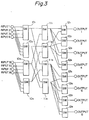
- FIG. 3 is a diagram illustrating an example of an outlined construction of the networking apparatus.
- the networking apparatus of Fig. 3 has three stages of switch units, eight input ports, and eight output ports.
- 10 1 to 10 4 each denote a switch unit in the first stage
- 11 1 to 11 4 each denote a switch unit in the second stage
- 12 1 to 12 4 each denote a switch unit in the final stage.
- Fig. 3 only routes for data transfer are indicated by lines connected between input ports and switch units in the first stage, between the switch units in the adjacent stages, and between the switch units in the final stage and the output ports. The flows of the control signals are explained later with reference to Fig. 4.
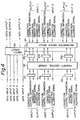
- FIG. 4 is a diagram illustrating an example construction of the switch unit which is used in stages other than the final stage in a networking apparatus having a structure, for example, as indicated in Fig. 1.
- reference numeral 20 denotes a switch circuit
- 21 1 , 21 2 , ⁇ 21 N each denote a register on the request input side
- 22 denotes a priority control circuit
- 23 1 , 23 2 , ⁇ 23 N each denote a register on the allowance output side
- 24 denotes an information switch circuit.
- the switch circuit 20 provides a plurality of routes (paths) for data transfer operations between a plurality of data processing apparatuses. As explained below, the switch circuit 20 is controlled by a group of pieces of partial information to be used for controlling the switch circuit 20, among pieces of connection request information corresponding to connection request signals allowed by the priority control circuit 22.
- the switch circuit 20 in Fig. 4 comprises N data input ports and M data output ports, and can simultaneously establish a route connecting each of the N data input ports with the respectively corresponding one of the M data output ports. For example, in the case wherein the construction of Fig.
- the N data input ports of the switch circuit 20 are respectively connected to a plurality of data output ports (not shown) of a plurality of data processing apparatuses, and the M data output ports are respectively connected to one or more of the data input ports of one of the switch units in the second stage.
- Such a switch circuit can be easily constructed by combining a plurality of selector circuits in a plurality of stages.
- the above control of switch circuit means control of the selector circuits in the switch circuit 20.
- Each of the data processing apparatuses stores in a memory (not shown) provided therein, a list of pieces of connection control information to be supplied to the networking apparatus for establishing routes for transferring data to the other data processing apparatuses, respectively.
- the respective piece of connection control information indicates what control information is to be transferred to the respective switch units in the respective stages of the networking apparatus. For example, in the case wherein the networking apparatus is constituted by three stages as indicated in Fig.
- the connection control information may contain: (a piece of control information to be transferred to the switch circuit 20 in a switch unit in the first stage); (a piece of control information to be transferred to the switch circuit 20 in a switch unit in the second stage); and (a piece of control information to be transferred to the switch circuit 20 in a switch unit in the final stage).
- more than one route may be established from one data processing apparatus to each data processing apparatus, and therefore, more than one piece of such connection control information may be stored for each address (data processing apparatus), in the above memory.
- the data processing apparatus on the sending side reads one piece of the connection control information for a route to the above other data processing apparatus, from the above list, and transfers the set of connection control information together with a connection request signal, through a corresponding one of the data input ports of a switch unit to which the data processing apparatus on the sender side is connected.
- the plurality of registers 21 1 , 21 2 , ... 21 N on the request input side, which are provided on the request input side of the priority control circuit 22, are respectively connected to the output ports for the connection control information and the connection request signals, in the respectively corresponding data processing apparatuses.
- the plurality of plurality of registers 21 1 , 21 2 , ... 21 N on the request input side is provided corresponding to the data input ports of the switch circuit 20.
- the connection control information and the connection request signals from the data processing apparatus (on the sender side) are respectively latched in the plurality of registers 21 1 , 21 2 , ... 21 N on the request input side of the priority control circuit 22, and are applied to the priority control circuit 22.
- more than one data processing apparatus may simultaneously apply a plurality of connection request signals and a plurality of pieces of connection control information accompanying the respective connection request signals, to the plurality of registers 21 1 , 21 2 , ... 21 N on the request input side.
- the priority control circuit 22 receives the above-mentioned pieces of partial information included in the pieces of connection control information accompanying the connection request signals, and simultaneously gives allowances to the connection request signals corresponding to the pieces of connection control information when the above pieces of partial information in the connection control information indicate requests for routes which can be simultaneously established by the switch circuit 20, or gives an allowance to one of the connection request signals corresponding to the pieces of connection control information when the above pieces of partial information in the connection control information indicates requests for routes which cannot be simultaneously established by the switch circuit 20.
- connection request signals is determined based on a predetermined priority order, taking into consideration a condition that an allowance is obtained for the piece of connection control information corresponding to the connection request signal, in a switch unit in all of the following stage(s), as explained later.
- a plurality of registers 23 1 , 23 2 , ... 23 N on the allowance output side are provided corresponding to the plurality of registers on the input side of the priority control circuit 22.
- the connection request signal allowed by the priority control circuit 22 and the accompanying piece of connection control information pass through the priority control circuit 22, and are latched in the corresponding one of the registers 23 1 , 23 2 , ... 23 N on the allowance output side.
- the priority control circuit receives a plurality of connection requests, and outputs an allowance to one of the connection requests in accordance with a predetermined priority order when the plurality of requests conflict. Since various constructions are known for realizing such a priority control circuit, details of the construction of the priority control circuit are not shown here.
- connection request signals and accompanying piece of connection control information are output from the respectively corresponding registers 23 1 , 23 2 , ... 23 N on the allowance output side.
- the above-mentioned pieces of partial information to be used for controlling the switch circuit 20, included in the pieces of connection control information, are branched, and are applied to the control input terminals of the switch circuit 20.
- the switch circuit 20 can be controlled by the control information allowed by the priority control circuit 22 so that the routes according to the control information allowed by the priority control circuit 22 are established in the switch circuit 20.
- the above pieces of partial information applied to the switch circuit 20, are also applied to the information switch circuit 24 for controlling the information switch circuit 24.
- the information switch circuit 24 has a construction similar to the construction of the switch circuit 20.
- the switch circuit 20 is provided for providing the routes for transferring data, while the information switch circuit 24 is provided for transferring connection request signals and pieces of connection control information used for establishing the routes for the data transfer in the switch circuit 20, located along the respectively corresponding routes for the data transfer in the same directions as those of the corresponding data transfer operations, and for transferring connection allowance signals which are returned from the switch unit in the following stages, along the above routes in the directions opposite to those of the corresponding data transfer operations. Therefore, switching in the switch circuit 20 and the information switch circuit 24 are performed in the same manner and at the same timing.
- each of the registers 23 1 , 23 2 , ... 23 N in the above switch unit is applied to a corresponding input terminal of a register provided on the request input side of a priority control circuit in another switch unit which contains another switch circuit to which the output data of the switch circuit 20 of the above switch unit is applied.
- connection allowance signal indicates whether or not a route is allowed (established) in all of the following stage(s) in response to a corresponding connection request signal and an accompanying piece of connection control information.
- the connection allowance signal is active.
- connection allowance signals returned from a switch unit in the following stage(s) is input from a corresponding input terminal of the priority control circuit 22 through the information switch circuit 24.
- the priority control circuit 22 recognizes whether or not a route is allowed (established) in all of the following stage(s) in response to a corresponding connection request signal and an accompanying piece of connection control information, based on whether or not the connection allowance signal is active.
- a priority control circuit in each of the switch unit in the following stage(s) operates in the same way as the above explained priority control circuit 22 of Fig. 4.
- the priority control circuit 22 In order to determine whether or not a route corresponding to a connection request signal which is allowed in the priority control circuit 22, is allowed (established) in all of the following stage(s) in response to a corresponding connection request signal and an accompanying piece of connection control information, the priority control circuit 22 transfers connection request signals allowed therein and pieces of connection control information accompanying the allowed connection request signals to the switch units in the following stage(s), and receives corresponding connection allowance signals returned from the switch units in the following stage(s). An allowance to a connection request signal corresponding to which an active connection allowance signal is received from the following stage(s), is confirmed.
- connection request signal An allowance to a connection request signal corresponding to which an inactive connection allowance signal is received from the following stage(s), is not confirmed, and then, the priority control circuit 22 stops the output therefrom of the connection request signal which is not confirmed, and a piece of connection control information accompanying the connection request signal.
- the priority control circuit 22 receives one or more other connection request signal which has not been allowed by the priority control circuit 22, the priority control circuit 22 gives an allowance to one of such connection request signals having the highest priority among the connection request signals, according to the predetermined priority order.
- the newly allowed connection request signal and a piece of connection control information accompanying the allowed connection request signal are output from the priority control circuit 22, instead of the above connection request signal which is not confirmed by the connection allowance signal from the following stage(s) and the accompanying piece of connection control information. Then, the confirmation of the allowance by the connection allowance signal from the following stage(s) is performed for the new connection request signal and the accompanying connection control information.
- the priority control circuit 22 When each route is established by the above operations in the priority control circuit 2, the priority control circuit 22 generates a connection allowance signal, and outputs the same from a corresponding connection allowance signal output terminal, which is provided on the request input side of the priority control circuit 22.
- the output of the connection allowance signal is applied to a connection allowance signal input terminal of the information switch circuit 24 in the corresponding switch unit in the preceding stage.
- the output of the connection allowance signal is transferred to the data processing apparatus which outputs the connection request signal corresponding to the connection allowance signal.
- connection allowance signal transferred to the data processing apparatus which outputs the connection request signal corresponding to the connection allowance signal indicates that "a physical link in response to the connection request signal is established in the networking apparatus."
- the data processing apparatus can start the operation of transferring data in accordance with a predetermined protocol when the connection allowance signal is received.
- FIG. 5 is a diagram illustrating an example construction of the switch unit to be used in the final stage in the networking apparatus having a structure, for example, as indicated in Fig. 1. Since there is no transfer operation of connection request signals and the connection control information to the following stage(s), and no receipt of the connection allowance signals in a switch unit in the final stage, the information switch circuit 24 (Fig. 4) is unnecessary. The connection request signals allowed by the priority control circuit 22 in the switch unit of the final stage, are directly applied to the connection allowance signal input terminals of the priority control circuit 22.
- the data outputs of the switch circuit 20 in the switch unit in the final stage are respectively connected to data input ports (not shown) of the corresponding data processing apparatuses which are destinations of the routes established in the networking apparatus.
- a construction (Fig. 6) for generating and transferring an abnormality informing signal in a switch unit in the final stage, two types of constructions (Figs. 7 to 9) for generating and transferring an abnormality informing signal in switch units in the first and second (intermediate) stages, and a construction (Fig. 10) for detecting abnormality in a priority control circuit, are explained.
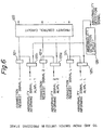
- Figure 6 is a diagram illustrating an example construction of the switch unit to be used in the final stage in the first and second embodiments of the networking apparatus, for detecting and informing of abnormality.
- reference numerals 121 1 to 121 L each denote a register on the request input side, as indicated by 21 1 to 21 N in Fig. 5; 122 denotes a priority control circuit, as indicated by 22 in Fig. 5; 125 1 to 125 L denote a plurality of AND gates respectively provided corresponding to the registers 121 1 to 121 L on the request input side, and 126 denotes an abnormality detection circuit.
- the abnormality detection circuit 126 detects an abnormality in the operation of the priority control circuit 122 in the switch unit.
- the detailed construction of the abnormality detection circuit 126 is explained later with reference to Fig. 10.
- the abnormality detection circuit 126 When the abnormality detection circuit 126 detects an abnormality in the operation of the priority control circuit 122 in the switch unit, the abnormality detection circuit 126 outputs an active abnormality detection signal.
- the output of the abnormality detection circuit 126 is applied to one of input terminals of each of the plurality of AND gates 125 1 to 125 L .
- the above-mentioned connection request signals output from the registers 121 1 to 121 L on the request input side, are applied to the other input terminals of the respective AND gates 125 1 to 125 L .
- ALMfn-N of the plurality of AND gates 125 1 to 125 L are respectively transferred, as abnormality informing signals from the final stage, to switch units in the preceding stage, which supply the corresponding connection request signals to the registers 121 1 to 121 L on the request input side.
- Each of the above abnormality informing signals ALMfn-1, ALMfn-2, ... ALMfn-N is applied to an abnormality informing signal input ports (explained later with reference to Fig. 7) corresponding to an output port in an information switch circuits 24 in a switch unit in the preceding stage, which output port outputs the connection request signal corresponding to the abnormality informing signal. Due to the provision of the plurality of AND gates, each of the abnormality informing signals is not sent to the corresponding switch unit in the preceding stage when a connection request signal corresponding to the abnormality informing signals is not active.
- Figure 7 is a diagram illustrating an example construction of the switch unit to be used in stages other than the final stage in the first embodiment of the networking apparatus, for detecting and informing of abnormality.
- reference numerals 21 1 to 21 N each denote the register on the request input side in Fig. 4; 22 denotes the priority control circuit in Fig. 4; 25 1 to 25 N denote a plurality of AND gates respectively provided corresponding to the registers 21 1 to 21 N on the request input side, and 39 denotes an OR gate.
- ALMi-J denote abnormality informing signals which are transferred from switch units in the following stage(s), where J is an integer equal to the number of the data output ports of the switch circuit 20 (which is indicated in Fig. 4 and not indicated in Fig. 7) in the switch unit explained here with reference to Fig. 7.
- abnormality informing signal input ports are provided in each switch unit in stages other than the final stage, for inputting the above abnormality informing signals ALMi-1, ALMi-2 ... ALMi-J, corresponding to the output ports for outputting the allowed connection request signals in the information switch circuit 24.
- the abnormality informing signals are transferred from the switch units in the following stage(s) along the routes of the corresponding connection request signals (and the pieces of connection control information) in directions opposite to the respective connection request signals, and are applied through the above abnormality informing signal input ports to a plurality of input terminals of the OR gate 39.
- the output of the abnormality detection circuit 26 is applied to the other input terminal of the OR gate 39.
- the output of the OR gate 39 is active when abnormality is detected in a priority control circuit in at least one of the switch units in the following stage(s) to which the connection request signals from the subject switch unit have been transferred, or when abnormality in the priority control circuit 22 in the subject switch unit is detected by the abnormality detection circuit 26.
- the output of the OR gate 39 is applied to one of input terminals of each of the plurality of AND gates 25 1 to 25 N .
- the connection request signals output from the registers 21 1 to 21 N on the request input side, are applied to the other input terminals of the respective AND gates 25 1 to 25 N .
- ALM(i-1)-N of the plurality of AND gates 25 1 to 25 N are respectively transferred, as abnormality informing signals, to switch units in the preceding stage (when the subject switch unit is not in the first stage) or to data processing apparatuses (when the subject switch unit is in the first stage), which supply the corresponding connection request signals to the registers 121 1 to 121 L on the request input side.
- each of the abnormality informing signals is not sent to the corresponding switch unit in the preceding stage when a connection request signal corresponding to the abnormality informing signals is not active.
- each of the above abnormality informing signals ALM(i-1)-1, ALM(i-1)-2, ⁇ ALM(i-1)-N is applied to an abnormality informing signal input ports (explained later with reference to Fig. 7) corresponding to an output port in an information switch circuits 24 in a switch unit in the preceding stage, which output port outputs the connection request signal corresponding to the abnormality informing signal.
- an abnormality informing signal input ports explained later with reference to Fig. 7
- each data processing apparatus can recognize whether or not trouble has occurred in any of switch units located along the route of data transfer which the data processing apparatus requests to establish.
- the data processing apparatus can transfer another request for requesting the estabitablishnt of a different route, to the networking apparatus.
- Figure 8 is a diagram illustrating an example construction of the switch unit to be used in intermediate stages other than the first and final stages in the second embodiment of the networking apparatus, for detecting and informing of abnormality.
- the following explanations of the second embodiments are made based on a switch unit of three stages for ease of explanation, it is easy to construct a switch unit of n stages, where n is an integer other than three, based on the following explanations.
- Fig. 8 reference numerals 221 1 to 221 T each denote a register on the request input side, as indicated by 21 1 to 21 N in Fig. 4; 222 denotes a priority control circuit, as indicated by 22 in Fig. 4; 227 1 to 227 T denote a plurality of AND gates respectively provided corresponding to the registers 221 1 to 221 T on the request input side, 226 denotes an abnormality detection circuit, and 41 denotes an abnormality informing signal switch circuit.
- ALMi-1, ALMi-2 ⁇ ALMi-S denote abnormality informing signals which are transferred from switch units in the following stage(s), where S is an integer equal to the number of the data output ports of the switch circuit 20 (which is indicated in Fig. 4 and not indicated in Fig. 8) in the subject switch unit explained here with reference to Fig. 8.
- the abnormality informing signal switch circuit 41 has abnormality informing signal input ports, for inputting the above abnormality informing signals ALMi-1, ALMi-2 ⁇ ALMi-S, corresponding to the output ports for outputting the allowed connection request signals in the information switch circuit 24.
- the abnormality informing signal switch circuit 41 also has a plurality of output ports for outputting signals C1, C2, ⁇ CT.
- the above abnormality informing signals ALMi-1, ALMi-2 ⁇ ALMi-S input from the abnormality informing signal input ports of the abnormality informing signal switch circuit 41 are connected to the output ports thereof in the same manner as the connections of the connection allowance signals in the information switch circuit 24 (Fig. 4) in the same switch unit. These connections are realized by applying the aforementioned group of pieces of partial information to be used for controlling the switch circuit 20, to the abnormality informing signal switch circuit 41 as control information at the same time as the timing of applying the same to the information switch circuit 24 in Fig. 4.
- the above abnormality informing signals ALMi-1, ALMi-2 ⁇ ALMi-S are arranged in the order of the corresponding connection request signals.
- Each of the outputs C1, C2, ⁇ CT (the ordered abnormality informing signals ALMi-1, ALMi-2 ⁇ ALMi-S) are applied to one of two input terminals of a corresponding one of the gate circuits 227 1 , 227 2 , ⁇ 227 T .
- the abnormality detection circuit 226 detects an abnormality in the priority control circuit 222 to output abnormality detection signal.
- the abnormality detection signal output from the abnormality detection circuit 226 is applied to the other of the input terminals of the gate circuits 227 1 , 227 2 , ⁇ 227 T .
- Each of the gate circuits 227 1 , 227 2 , ⁇ 227 T receives at a control input terminal thereof the output (the corresponding connection request signal) of a corresponding one of the registers 221 1 , 221 2 , ⁇ 221 T , as a gate control signal.
- the output signal ALM3-k' corresponds to a corresponding one of the above ordered abnormality informing signal ALMi-1, ALMi-2 ⁇ ALMi-S, and the output signal ALM2-k corresponds to the abnormality detection signal generated within the same switch unit.
- the above output signals ALM3-k' and ALM2-k from each gate circuit 227 k are transferred to a switch unit in the preceding stage on the route of the corresponding connection request signal.
- Figure 9 is a diagram illustrating an example construction of the switch unit to be used in the first stage in the second embodiment of the networking apparatus, for detecting and informing of an abnormality.
- reference numerals 321 1 to 321 p denote registers on the request input side, corresponding to the registers 21 1 to 21 N on the request input side in Fig. 4;
- 322 denotes a priority control circuit corresponding to the priority control circuit 22 in Fig. 4;
- 326 denotes an abnormality detection circuit;
- 42 denotes an abnormality informing signal switch circuit.
- the abnormality informing signal switch circuit 42 receives the above-mentioned output signals ALM3-k' and ALM2-k output from each gate circuit 227 k of Fig. 8 for each route of the connection request signal passing through the subject switch unit from a corresponding one of the switch units in the following stages.
- the abnormality detection circuit 326 detects and abnormality in the priority control circuit 322 and output an abnormality detection signal.
- the abnormality detection signal output from the abnormality detection circuit 326 is applied to the other of the input terminals of the gate circuits 327 1 , 327 2 , ⁇ 327 P .
- Each of the gate circuits 327 1 , 327 2 , ⁇ 327 P receives at a control input terminal thereof the output (the corresponding connection request signal) of a corresponding one of the registers 321 1 , 321 2 , ⁇ 321 P , as a gate control signal.
- the output signal ALM3-m'' corresponds to an abnormality informing signal generated in the third stage on the route of a corresponding connection request signal
- the output signal ALM2-m' corresponds to an abnormality informing signal generated in the second stage on the route of the corresponding connection request signal
- the output signal ALM1-m corresponds to the abnormality detection signal generated within the same switch unit.
- the abnormality informing signal switch circuit 41 in a switch unit which is used in the i-th stage (i is an integer) where n is an integer can be constructed so that the abnormality informing signal switch circuit receives (n-i) abnormality informing signals in parallel for each route of the connection request signal, and the parallel abnormality informing signals are switched in the same manner as the abnormality informing signals input into the abnormality informing signal switch circuit 41 explained above, to be applied to a corresponding gate circuit which has (n-i) +1 input terminals, instead of the above two or three input terminals in the gate circuit 227 k in Fig. 8 or 327 k in Fig. 9.
- each data processing apparatus which has output a connection request signal can receive in parallel the abnormality informing signals corresponding to the respective stages on the route of the connection request signal. Namely, each data processing apparatus which has output a connection request signal to the networking apparatus, can recognize where an abnormality occurs on the route which the connection request signal is requesting to establish in the networking apparatus. Therefore, each data processing apparatus can select another piece of connection control information among the aforementioned more than one piece of connection control information so that a route requested by the selected piece of connection control information does not pass through the switch unit in which the abnormality is detected, and can resend a connection request signal accompanied by another piece of connection control information among the aforementioned more than one piece of connection control information.
- This operation can be performed in accordance with a program which is installed in each data processing apparatus in advance of the operation of the multiprocessor system.
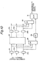
- Figure 10 is a diagram illustrating an example construction of the abnormality detecting circuit to be used in the first and second embodiments of the present invention.
- reference numerals 21 1 , 21 2 , ⁇ 21 N each denote the register on the request input side of Fig. 4, 22 denotes the priority control circuit of Fig. 4, 23 1 , 23 2 , ⁇ 23 N each denote the register on the allowance output side of Fig. 4, 28 and 30 each denote an OR gate, 29 denotes a flip flop circuit, and 31 denotes an exclusive OR (EOR) gate.
- EOR exclusive OR
- the OR gate 28 outputs an active signal when at least one of the plurality of registers 21 1 , 21 2 , ⁇ 21 N on the request input side, outputs an active connection request signal.
- the output of the OR gate 28 is applied to the flip flop circuit 29, and is latched therein.
- the OR gate 30 outputs an active signal when at least one of the plurality of registers 23 1 , 23 2 , ⁇ 23 N on the allowance output side, outputs an active connection request signal.
- the outputs of the OR gate 30 and the flip flop circuit 29 are applied to the exclusive OR (EOR) gate 31.
- the exclusive OR (EOR) gate 31 outputs an active signal when only one of the OR gates 28 and 30 outputs an active signal.
- the priority control circuit 22 Since at least one active connection request signal is applied to the priority control circuit 22, the priority control circuit 22 should pass therethrough at least one of the at least one active connection request signal, and the at least one active connection request signal passed through the priority control circuit 22 should appear as an active output signal of at least one of the registers 23 1 , 23 2 , ⁇ 23 N on the allowance output side, the active output of the exclusive OR (EOR) gate 31 indicates that abnormality occurs in the priority control circuit 22. Therefore, the output of the exclusive OR (EOR) gate 31 is used as the aforementioned abnormality detection signal.
Landscapes
- Engineering & Computer Science (AREA)
- Theoretical Computer Science (AREA)
- Quality & Reliability (AREA)
- Physics & Mathematics (AREA)
- General Engineering & Computer Science (AREA)
- General Physics & Mathematics (AREA)
- Multi Processors (AREA)
- Data Exchanges In Wide-Area Networks (AREA)
- Small-Scale Networks (AREA)
- Debugging And Monitoring (AREA)
- Bus Control (AREA)
- Computer And Data Communications (AREA)
- Hardware Redundancy (AREA)
Claims (13)
- Système multiprocesseur comprenant un appareil de gestion de réseau (2) et une pluralité d'appareils de traitement de données (11 à 1n), où des données peuvent être transférées via l'appareil de gestion de réseau (2) depuis un appareil de ladite pluralité d'appareils de traitement de données à un quelconque autre appareil de ladite pluralité d'appareils de traitement de données ; ou :ledit appareil (2) de gestion de réseau comprend :une unité (4) de commande de priorité destinée à recevoir au moins un élément d'information de demande de connexion, qui est délivré depuis au moins un appareil de ladite pluralité d'appareils de traitement de données (11 à 1n); à déterminer, sur la base d'un ordre de priorité prédéterminé, au moins un chemin qui est demandé par ledit au moins un élément d'information de demande de connexion, et qui peut être établi concurremment dans une unité de commutation (3); à délivrer au moins un signal d'autorisation de connexion audit au moins un appareil de la pluralité d'appareils de traitement de données qui délivre l'élément d'information de demande de connexion demandant le chemin déterminé; et à commander l'unité de commutation (3) de façon que ledit au moins un chemin soit établi dans l'unité de commutation (3) ;l'unité de commutation (3) étant destinée à y établir ledit au moins un chemin déterminé par l'unité de commande de priorité (4), sous commande de l'unité de commande de priorité (4) ; etune unité (5) de détection d'anomalie servant à contrôler le fonctionnement de l'unité de commande de priorité (4) ; à produire un signal d'information d'anomalie lorsqu'une anomalie est détectée dans le fonctionnement de l'unité de commande de priorité (4) ; et à délivrer le signal d'information d'anomalie à l'appareil de traitement de données qui a délivré l'élément d'information de demande de connexion ; etchaque appareil de la pluralité d'appareils de traitement de données (11 à 1n) comprenant une unité de délivrance d'information de demande de connexion servant a produire l'élément d'information de demande de connexion et à délivrer l'élément d'information de demande de connexion à l'unité de commande de priorité (4) de l'appareil de gestion de réseau (2).
- Système multiprocesseur selon la revendication 1, où l'élément d'information de demande de connexion comporte un signal de demande de connexion qui indique si l'appareil de traitement de données qui a délivré l'élément d'information de demande de connexion possède une demande pour une connexion, et un élément d'information de commande d'unité de commutation servant à commander l'unité de commutation (3) de façon que l'unité de commutation (3) établisse un chemin qui raccorde l'appareil de traitement de données à une destination demandée en fonction de l'élément d'information de commande d'unité de commutation.
- Système multiprocesseur selon la revendication 2, où chaque appareil de la pluralité d'appareils de traitement de données (11 à 1n) comprend une unité de stockage d'information de commande de commutation servant à stocker au moins un élément d'information de commande de commutation.
- Système multiprocesseur selon la revendication 3, où chaque appareil de la pluralité d'appareils de traitement de données (11 à 1n) comprend une unité servant à lire un élément dudit au moins un élément d'information de commande de commutation dans l'unité de stockage d'information de commande de commutation, afin d'établir le chemin de transfert de données avant l'exécution du transfert de données; et à délivrer l'élément d'information de demande de connexion à l'appareil de gestion de réseau.
- Système multiprocesseur selon la revendication 4, où chaque appareil de la pluralité d'appareils de traitement de données (11 à 1n) comprend une unité de recherche d'information supplémentaire destinée à recevoir le signal d'information d'anomalie en réponse à la délivrance de l'élément d'information de commande de commutation à l'appareil (2) de gestion de réseau, et à déterminer si un deuxième élément d'information de commande de commutation visant à établir un autre chemin conduisant à la même destination que celle du chemin demandé par l'élément d'information de commande de commutation est stocké dans l'unité de stockage d'information de commande de commutation ; etune autre unité de délivrance d'information servant à lire l'élément d'information de commande de commutation, comportant l'élément d'information de commande de commutation dans un deuxième élément d'information de demande de connexion, et à délivrer le deuxième élément d'information de demande de connexion lorsque le deuxième élément d'information de commande de commutation a été trouvé comme étant stocké dans l'unité de stockage d'information de commande de commutation.
- Système multiprocesseur selon l'une quelconque des revendications précédentes, où l'unité (5) de détection d'anomalie détecte au titre de l'anomalie une contradiction entre un signal d'entrée et un signal de sortie de l'unité (4) de commande de priorité.
- Système multiprocesseur selon l'une quelconque des revendications 1 à 5, où l'unité (5) de détection d'anomalie détecte au titre de l'anomalie une première condition contradictoire selon laquelle l'unité de commande de priorité (4) ne délivre pas un signal d'autorisation de connexion lorsque l'unité de commande de priorité (4) reçoit au moins un élément d'information de demande de connexion, ou bien une deuxième condition contradictoire selon laquelle l'unité de commande de priorité (4) délivre un signal d'autorisation de connexion lorsque l'unité de commande de priorité (4) ne reçoit pas un élément d'information de demande de connexion.
- Système multiprocesseur selon l'une quelconque des revendications 2 à 7, où l'unité (5) de détection d'anomalie comprend :une unité (26) de production de signal de détection d'anomalie servant à produire, en réponse à la détection de l'anomalie, un signal de détection d'anomalie indiquant que l'unité de détection d'anomalie (5) a détecté l'anomalie, etune unité de portes (251 à 25N) destinée à recevoir le signal de détection d'anomalie et le signal de demande de connexion, et à délivrer au titre du signal d'information d'anomalie, le signal de détection d'anomalie au seul appareil parmi la pluralité d'appareils de traitement de données qui délivre le signal de demande de connexion.
- Système multiprocesseur selon l'une quelconque des revendications précédentes, où ladite unité de commutation (3) est constituée d'une pluralité d'étages et d'une pluralité de circuits de commutation (20) où chaque étage comprend au moins un circuit de la pluralité de circuits de commutation (20) ;chaque circuit de commutation (20) possède au moins un port, ou accès, d'entrée et au moins un port, ou accès, de sortie, et fournit un premier chemin partiel qui constitue une partie du chemin servant au transfert de données dans l'étage auquel le circuit de commutation (20) appartient ;chaque élément d'information de commande de commutation contenu dans chaque élément d'information de demande de connexion comprend une pluralité d'éléments d'information partielle de commande de commutation à utiliser pour commander les unités de commutation des étages respectifs qui se trouvent sur le chemin du transfert de données demandé par l'élément d'information de demande de connexion ;l'unité de commande de priorité (4) comprend une pluralité de circuits de commande de priorité (22), prévue pour la pluralité respective de circuits de commutation (20), servant chacun à commander le circuit correspondant de la pluralité de circuits de commutation (20), de façon que le circuit de commutation (20) correspondant de chaque étage établisse le premier chemin partiel en fonction d'un élément correspondant de la pluralité d'éléments d'information partielle de commande de commutation ;l'unité (5) de détection d'anomalie comprend une pluralité d'unités de détection et d'information d'anomalie, prévues pour chaque circuit de la pluralité de circuits de commutation (20), chaque unité de détection et d'information d'anomalie comprenant :un circuit de détection d'anomalie (26, 126) servant à détecter une anomalie dans le circuit de commande de priorité correspondant à l'une quelconque ou à chacune des unités de détection et d'information d'anomalie, et à produire un signal de détection d'anomalie ;une unité de transfert de signal de détection d'anomalie servant à transférer le signal de détection d'anomalie le long du chemin destiné au transfert de données passant par le circuit de commutation (20) qui correspond à l'unité de détection et d'information d'anomalie contenant le circuit de détection d'anomalie (26, 126) qui a produit le signal de détection d'anomalie, dans un sens qui est opposé au sens du transfert de données ; etune unité d'information d'anomalie servant à détecter, pour chaque chemin servant au transfert de données, la production d'un signal de détection d'anomalie par l'un quelconque ou l'un correspondant des circuits de détection d'anomalie (26, 126) des étages respectifs placés le long du chemin, à produire un signal d'information d'anomalie, et à délivrer le signal d'information d'anomalie à l'appareil de traitement de données qui délivre l'élément d'information de demande de connexion demandant le chemin.
- Système multiprocesseur selon la revendication 9, où l'appareil (2) de gestion de réseau comprend un circuit (24) de commutation d'information de demande de connexion, prévu pour chacun des circuits de commutation (20) des étages autres que l'étage final, afin de connecter un port d'entrée de celui-ci avec un port de sortie de celui-ci de la même manière que le circuit de commutation (20) correspondant qui connecte son port d'entrée à son port de sortie, afin de former un deuxième chemin partiel permettant le transfert d'un élément de l'information de demande de connexion, de façon que l'élément d'information de demande de connexion puisse être délivré au circuit de commande de priorité (22) qui correspond au circuit de commutation (20) placé le long de chaque chemin, et le signal de demande de connexion peut être fourni à l'unité de détection et d'information d'anomalie qui correspond au circuit de commande de priorité ;l'information de demande de connexion délivrée par l'appareil de traitement de données est fournie au circuit de commande de priorité du premier étage et est ensuite fournie au circuit de commande de priorité correspondant au circuit de commutation de chaque étage placé le long de chaque chemin destiné au transfert de données, via le deuxième chemin partiel fourni par le circuit (24) de commutation d'information de demande de connexion ;le signal de demande de connexion compris dans l'information de demande de connexion délivrée par l'appareil de traitement de données est fourni à l'unité de détection et d'information d'anomalie du premier étage, puis est fourni à l'unité de détection et d'information d'anomalie correspondant au circuit de commutation de chaque étage placé le long de chaque chemin servant au transfert de données, via le circuit de commutation d'information de demande de connexion ;l'appareil (2) de gestion de réseau comprend en outre un circuit (24) de commutation de signal d'autorisation de connexion, prévu pour chaque circuit de commutation d'information de demande de connexion, afin de fournir un troisième chemin partiel dans le sens opposé au sens du deuxième chemin partiel fourni par le circuit (24) de commutation d'information de demande de connexion correspondant, de façon qu'un signal d'autorisation de connexion partiel délivré par un circuit de commande de priorité du ou des étages suivants soit transféré, dans le sens opposé au sens de l'élément d'information de demande de connexion, au circuit de commande de priorité de l'étage précédent, le long du trajet servant à fournir l'élément d'information de demande de connexion au circuit de commande de priorité correspondant au circuit de commutation de chaque étage placé le long de chaque trajet servant au transfert de données ;le circuit (22) de commande de priorité des étages autres que le premier étage et l'étage final reçoit, pour chacun, l'élément d'information de demande de connexion et le signal d'autorisation de connexion partiel que délivre le circuit de commande de priorité (22) de l'étage ou des étages suivants via le circuit de commutation de signal d'autorisation de connexion ; il détermine, au titre du premier chemin partiel du circuit de commutation (20) correspondant au circuit de commande de priorité (22), l'un des candidats pour le premier trajet partiel dans le circuit correspondant au circuit de commande de priorité, lorsque ce candidat pour le premier trajet partiel est demandé par l'information de commande de commutation partielle de l'élément de l'information de demande de connexion, et peut être concurremment établi dans le circuit de commutation (20), et le signal d'autorisation de connexion partiel pour ce candidat au premier chemin partiel est reçu de la part du circuit de commande de priorité de l'étage ou des étages suivants placés le long d'un chemin servant au transfert de données qui contient ce candidat au premier chemin partiel ; il commande le circuit de commutation correspondant, le circuit (24) de commutation de signal de demande de connexion correspondant, et le circuit de commutation de signal d'autorisation de connexion correspondant, de sorte que le premier chemin partiel déterminé est établi dans le circuit de commutation correspondant, le deuxième chemin partiel est établi dans le circuit de commutation de signal de demande de connexion qui correspond au circuit de connutation (20) de la même manière que le premier chemin partiel, et le troisième chemin partiel allant dans le sens opposé au deuxième chemin partiel est établi dans le circuit de commutation de signal d'autorisation de connexion correspondant au circuit de commutation de signal de demande de connexion ; et il délivre le signal d'autorisation de connexion partiel correspondant au premier chemin partiel ;le circuit de commande de priorité (122) de l'étage final reçoit l'élément d'information de demande de connexion ; il détermine, au titre du premier chemin partiel dans le circuit de commutation du premier étage, l'un des candidats au premier chemin partiel du circuit de commutation de l'étage final, lorsque ce candidat au premier trajet partiel peut être établi de façon concurrente dans le circuit de commutation (20) et demandé par l'élément d'information partielle de commande d'unité de commutation servant à commander le circuit de commutation de l'étage final, inclus dans l'élément d'information de demande de connexion ; il commande le circuit de commutation (20) de façon que le candidat au premier chemin partiel soit établi dans le circuit de commutation (22) de l'étage final ; et il délivre le signal d'autorisation de connexion partiel à un circuit de commande de priorité (22) de l'étage précédent placé le long d'un chemin contenant le premier chemin partiel ;le circuit de commande de priorité (22) du premier étage reçoit l'élément d'information de demande de connexion et le signal d'autorisation de connexion partiel que délivre le circuit de commande de priorité (22) de l'étage ou des étages suivants via le circuit de commutation de signal d'autorisation de connexion ; il détermine, au titre du premier chemin partiel du circuit de commutation du premier étage, l'un des candidats au premier chemin partiel du circuit de commutation (20), qui est demandé par l'information partielle de commande d'unité de commutation se trouvant dans l'élément d'information de demande de connexion et peut concurremment être établi dans le circuit de commutation, et le signal d'autorisation de connexion partiel pour ce candidat au premier trajet partiel est reçu de la part du circuit de commande de priorité (22) de l'étage ou des étages suivants placé le long d'un chemin servant au transfert de données qui contient ce candidat au premier chemin partiel ; il commande le circuit de commutation correspondant (20), le circuit de commutation de signal de demande de connexion correspondant, et le circuit de commutation de signal d'autorisation de connexion correspondant, de façon que le premier chemin partiel déterminé soit établi dans le circuit de commutation correspondant (20), que le deuxième chemin partiel soit établi dans le circuit de commutation de signal de demande de connexion correspondant au circuit de commutation (20) de la même manière que le premier chemin partiel, et que le troisième chemin partiel allant dans le sens opposé au deuxième chemin partiel soit établi dans le circuit de commutation de signal d'autorisation de connexion correspondant au circuit de commutation de signal de demande de connexion ; et il délivre le signal d'autorisation de connexion partiel correspondant au premier chemin partiel à celui des appareils de traitement de données qui délivre l'élément d'information de demande de connexion demandant le chemin qui contient le premier chemin partiel déterminé ;chacune des unités de détection et d'information d'anomalie de l'étage final comprend une pluralité de portes d'information d'anomalie (1251 à 125L), chaque porte prévue correspondant à l'un des ports d'entrée du circuit de commutation correspondant à l'unité de détection et d'information d'anomalie ; recevant le signal de demande de connexion inclus dans l'élément d'information de demande de connexion demandant un chemin qui contient le premier chemin partiel partant au niveau du port d'entrée correspondant, et le signal de détection d'anomalie produit par le circuit de détection d'anomalie de l'unité de détection et d'information d'anomalie ; et délivrant, au titre d'un signal d'information d'anomalie partiel, le signal de détection d'anomalie à une unité de détection et d'information d'anomalie de l'étage précédent dans le seul cas où le signal de demande de connexion est actif ; etl'appareil de gestion de réseau comprend, pour chaque étage de chaque chemin du transfert de données, un circuit de commutation de signal d'information d'anomalie prévu en correspondance avec chaque circuit de commutation de signal d'autorisation de connexion, afin d'établir pour un signal ou chaque signal d'information d'anomalie partiel délivré par une unité de détection et d'information d'anomalie un quatrième chemin partiel connectant un port d'entrée avec un port de sortie du circuit de commutation de signal d'information d'anomalie de la même manière que la connexion correspondante faite par le troisième chemin du circuit de commutation de signal d'autorisation de connexion, de façon qu'un signal d'information d'anomalie partiel délivré par une unité de détection et d'information d'anomalie de l'étage ou des étages suivants soit transféré au circuit de commande de priorité (22) correspondant au circuit de commutation (20) établissant le premier chemin partiel de l'étage dans le trajet.
- Système multiprocesseur selon la revendication 10, où :chaque unité de détection et d'information d'anomalie d'étages autres que l'étage final comprend une porte OU (39) destinée à recevoir comme premier signal de détection d'anomalie, le signal de détection d'anomalie produit par le circuit de détection d'anomalie de l'unité de détection et d'information d'anomalie, à recevoir, comme deuxième signal de détection d'anomalie, le signal de détection d'anomalie transféré depuis l'unité de détection et d'information d'anomalie de l'étage ou des étages suivants via le quatrième chemin partiel du circuit de commutation de signal d'information d'anomalie ; et à obtenir et délivrer la somme logique des premier et deuxième signaux de détection d'anomalie ;chaque unité de détection et d'information d'anomalie d'étages autres que le premier étage et l'étage final comprend une pluralité de premières portes de signal d'information d'anomalie (251 à 25N) chaque porte prévue correspondant à l'un des ports d'entrée du circuit de commutation correspondant, afin de recevoir le signal de demande de connexion inclus dans l'élément d'information de demande de connexion demandant le chemin qui part au port d'entrée correspondant et qui contient le premier chemin partiel, et la somme logique délivrée par la porte OU (39); et délivrant, comme autre signal d'information d'anomalie partiel la somme logique à l'unité de détection et d'information d'anomalie de l'étage précédent dans le seul cas où le signal de demande de connexion est actif ; etchacune des unités de détection et d'information d'anomalie du premier étage comprend une pluralité de deuxièmes portes de signaux d'information d'anomalie (251 à 25N), chaque porte prévue correspondant à l'un des ports d'entrée du circuit de commutation correspondant à l'unité de détection d'information d'anomalie; afin de recevoir le signal de demande de connexion inclus dans l'élément d'information de demande de connexion demandant le chemin qui part au port d'entrée correspondant et qui contient le premier chemin partiel, et la somme logique délivrée par la porte OU ; et de délivrer, comme autre signal d'information d'anomalie partiel, la somme logique à celui des appareils de traitement de données qui délivre l'élément d'information de demande de connexion seulement dans le cas où le signal de demande de connexion est actif.
- Système multiprocesseur selon la revendication 9, où l'identification est maintenue de l'étage dans lequel le signal de détection d'anomalie a été produit.
- Système multiprocesseur selon l'une quelconque des revendications 10, 11 et 12, où chaque unité de détection et d'information d'anomalie d'étages autres que le premier étage et l'étage final comprend une deuxième pluralité de portes d'information d'anomalie (2271 à 227T), prévue en correspondance avec un port d'entrée correspondant du circuit de commutation correspondant à l'unité de détection et d'information d'anomalie, afin de recevoir le signal de demande de connexion contenant l'élément d'information de demande de connexion demandant un chemin contenant le premier chemin partiel qui part au port d'entrée, le signal de détection d'anomalie produit par le circuit de détection d'anomalie de chaque unité de détection et d'information d'anomalie et un ou plusieurs signaux d'information d'anomalie partiels délivrés par une unité de détection et d'information d'anomalie de l'étage ou des étages suivants via le quatrième chemin du circuit de commutation de signal d'information d'anomalie ; et à délivrer, sous la forme d'une pluralité de signaux d'information d'anomalie partiels venant de l'unité de détection et d'information d'anomalie, le signal de détection d'anomalie et le ou les signaux d'information d'anomalie en parallèle avec une unité de détection et d'information d'anomalie de l'étage précédent, dans le seul cas où le signal de demande de connexion est actif ; etchacune des unités de détection et d'information d'anomalie du premier étage comprend une troisième pluralité de portes de signaux d'information d'anomalie (3211 à 321p), chaque porte prévue correspondant à l'un des ports d'entrée du circuit de commutation correspondant à l'unité de détection et d'information d'anomalie; afin de recevoir le signal de demande de connexion inclus dans l'élément d'information de demande de connexion demandant le chemin contenant le premier chemin partiel qui part au port d'entrée correspondant, le signal de détection d'anomalie produit par le circuit de détection d'anomalie dans chaque unité de détection et d'information d'anomalie, et un ou plusieurs signaux d'information d'anomalie partiels délivrés par une unité de détection et d'information d'anomalie de l'étage ou des étages suivants via le quatrième chemin du circuit de commutation de signal d'information d'anomalie ; et de délivrer, au titre d'une pluralité de signaux d'information d'anomalie partiels venant de l'unité de détection et d'information d'anomalie, le signal de détection d'anomalie et le ou les signaux d'information d'anomalie en parallèle avec celui des appareils de traitement de données qui délivre l'élément d'information de demande de connexion, dans le seul cas où le signal de demande de connexion est actif.
Applications Claiming Priority (3)
| Application Number | Priority Date | Filing Date | Title |
|---|---|---|---|
| JP32003092 | 1992-11-30 | ||
| JP32003092A JP3461520B2 (ja) | 1992-11-30 | 1992-11-30 | マルチプロセッサシステム |
| JP320030/92 | 1992-11-30 |
Publications (3)
| Publication Number | Publication Date |
|---|---|
| EP0600581A2 EP0600581A2 (fr) | 1994-06-08 |
| EP0600581A3 EP0600581A3 (en) | 1997-03-05 |
| EP0600581B1 true EP0600581B1 (fr) | 2000-10-25 |
Family
ID=18116969
Family Applications (1)
| Application Number | Title | Priority Date | Filing Date |
|---|---|---|---|
| EP93306517A Expired - Lifetime EP0600581B1 (fr) | 1992-11-30 | 1993-08-18 | Système à multiprocesseur pour transférer des signaux de détection d'anomalies, générés dans des appareils de réseau, de retour au processeur, en parallèle avec la route de transfert des données |
Country Status (4)
| Country | Link |
|---|---|
| US (1) | US5572679A (fr) |
| EP (1) | EP0600581B1 (fr) |
| JP (1) | JP3461520B2 (fr) |
| DE (1) | DE69329592T2 (fr) |
Families Citing this family (10)
| Publication number | Priority date | Publication date | Assignee | Title |
|---|---|---|---|---|
| JP3459056B2 (ja) * | 1996-11-08 | 2003-10-20 | 株式会社日立製作所 | データ転送システム |
| WO2000018041A2 (fr) * | 1998-09-18 | 2000-03-30 | Harris Corporation | Mecanisme de liaison reparti pour reseau vhf |
| ES2211753T3 (es) * | 2000-09-29 | 2004-07-16 | Alcatel | Priorizador de tareas en una matriz de interconexion. |
| US20030005154A1 (en) * | 2001-06-29 | 2003-01-02 | Thurman Robert W. | Shared routing in a measurement system |
| US6892321B2 (en) * | 2001-07-17 | 2005-05-10 | International Business Machines Corporation | Transition to switch node adapter diagnostics using adapter device driver |
| US6848062B1 (en) | 2001-12-21 | 2005-01-25 | Ciena Corporation | Mesh protection service in a communications network |
| JP4087179B2 (ja) * | 2002-07-29 | 2008-05-21 | 富士通株式会社 | 加入者線端局装置 |
| GB2398650B (en) * | 2003-02-21 | 2006-09-20 | Picochip Designs Ltd | Communications in a processor array |
| JP2012128697A (ja) * | 2010-12-16 | 2012-07-05 | Hitachi Ltd | 情報処理装置 |
| JP6841362B1 (ja) | 2020-03-17 | 2021-03-10 | 住友大阪セメント株式会社 | リチウムイオン二次電池用正極材料、リチウムイオン二次電池用正極及びリチウムイオン二次電池 |
Family Cites Families (4)
| Publication number | Priority date | Publication date | Assignee | Title |
|---|---|---|---|---|
| US5161156A (en) * | 1990-02-02 | 1992-11-03 | International Business Machines Corporation | Multiprocessing packet switching connection system having provision for error correction and recovery |
| EP0505781B1 (fr) * | 1991-03-29 | 2001-10-17 | International Business Machines Corporation | Adaptateur de commutation de ligne série multi-media pour réseaux parallels et système d'ordinateurs hétérogènes et homologues |
| US5321813A (en) * | 1991-05-01 | 1994-06-14 | Teradata Corporation | Reconfigurable, fault tolerant, multistage interconnect network and protocol |
| US5345229A (en) * | 1992-09-17 | 1994-09-06 | International Business Machines Corporation | Adaptive switching apparatus for multi-stage networks |
-
1992
- 1992-11-30 JP JP32003092A patent/JP3461520B2/ja not_active Expired - Fee Related
-
1993
- 1993-08-12 US US08/105,174 patent/US5572679A/en not_active Expired - Lifetime
- 1993-08-18 DE DE69329592T patent/DE69329592T2/de not_active Expired - Fee Related
- 1993-08-18 EP EP93306517A patent/EP0600581B1/fr not_active Expired - Lifetime
Also Published As
| Publication number | Publication date |
|---|---|
| DE69329592D1 (de) | 2000-11-30 |
| US5572679A (en) | 1996-11-05 |
| EP0600581A2 (fr) | 1994-06-08 |
| DE69329592T2 (de) | 2001-03-15 |
| JPH06168218A (ja) | 1994-06-14 |
| EP0600581A3 (en) | 1997-03-05 |
| JP3461520B2 (ja) | 2003-10-27 |
Similar Documents
| Publication | Publication Date | Title |
|---|---|---|
| US5477536A (en) | Method and system for routing information between nodes in a communication network | |
| JP3709795B2 (ja) | コンピュータシステムと、コンピュータシステム内のモジュール間の通信方法 | |
| EP0430569B1 (fr) | Réseaux d'interconnexion à tolérance de fautes | |
| EP0600581B1 (fr) | Système à multiprocesseur pour transférer des signaux de détection d'anomalies, générés dans des appareils de réseau, de retour au processeur, en parallèle avec la route de transfert des données | |
| JP3574425B2 (ja) | 耐多重障害ネットワーク構造を利用したパケット処理方法 | |
| JPH04234247A (ja) | Atm交換装置による通信セルの受け入れ、伝達方法および回路装置 | |
| US6859430B1 (en) | Protection switching of virtual connections | |
| US5513321A (en) | Multiprocessor system discharging data in networking apparatus in response to off-line information from receiver-side processor | |
| US6940810B1 (en) | Protection switching of virtual connections at the data link layer | |
| US6938187B2 (en) | Tandem connection monitoring | |
| JPS61224750A (ja) | 伝送路障害区間検出通知方式 | |
| JP2004040726A (ja) | 光クロスコネクト装置 | |
| CN101467390B (zh) | 在帧交换网络中的虚链路的路由选择方法 | |
| JP5310735B2 (ja) | パケット転送装置、プロセッサ間通信システム、並列プロセッサシステムおよびパケット転送方法 | |
| JP2881185B2 (ja) | メッセージ切換装置 | |
| JP2009217581A (ja) | 欠陥誤り耐性機能付きクロスバーバス回路 | |
| KR100251702B1 (ko) | 비동기 전송 모드 네트웍에서 특정 디바이스의 고장 진단 방법 | |
| JPH0865329A (ja) | 伝送制御方式 | |
| JPH0222948A (ja) | 最小コストルーテイング制御方式 | |
| JP2730564B2 (ja) | 通信経路制御システム | |
| JPS6360941B2 (fr) | ||
| JPS6160042A (ja) | ノ−ドの配列順序識別方式 | |
| JPH01137747A (ja) | パケット交換方式 | |
| KR920009121A (ko) | 데이타 통신망 및 그제어방법 | |
| JPH01194631A (ja) | 伝送系異常検出方式 |
Legal Events
| Date | Code | Title | Description |
|---|---|---|---|
| PUAI | Public reference made under article 153(3) epc to a published international application that has entered the european phase |
Free format text: ORIGINAL CODE: 0009012 |
|
| AK | Designated contracting states |
Kind code of ref document: A2 Designated state(s): DE |
|
| PUAL | Search report despatched |
Free format text: ORIGINAL CODE: 0009013 |
|
| AK | Designated contracting states |
Kind code of ref document: A3 Designated state(s): DE FR GB |
|
| 17P | Request for examination filed |
Effective date: 19970701 |
|
| GRAG | Despatch of communication of intention to grant |
Free format text: ORIGINAL CODE: EPIDOS AGRA |
|
| 17Q | First examination report despatched |
Effective date: 19991108 |
|
| GRAG | Despatch of communication of intention to grant |
Free format text: ORIGINAL CODE: EPIDOS AGRA |
|
| GRAH | Despatch of communication of intention to grant a patent |
Free format text: ORIGINAL CODE: EPIDOS IGRA |
|
| RBV | Designated contracting states (corrected) |
Designated state(s): DE |
|
| GRAH | Despatch of communication of intention to grant a patent |
Free format text: ORIGINAL CODE: EPIDOS IGRA |
|
| GRAA | (expected) grant |
Free format text: ORIGINAL CODE: 0009210 |
|
| AK | Designated contracting states |
Kind code of ref document: B1 Designated state(s): DE |
|
| REF | Corresponds to: |
Ref document number: 69329592 Country of ref document: DE Date of ref document: 20001130 |
|
| EN | Fr: translation not filed | ||
| PLBE | No opposition filed within time limit |
Free format text: ORIGINAL CODE: 0009261 |
|
| STAA | Information on the status of an ep patent application or granted ep patent |
Free format text: STATUS: NO OPPOSITION FILED WITHIN TIME LIMIT |
|
| 26N | No opposition filed | ||
| PGFP | Annual fee paid to national office [announced via postgrant information from national office to epo] |
Ref country code: DE Payment date: 20080829 Year of fee payment: 16 |
|
| PG25 | Lapsed in a contracting state [announced via postgrant information from national office to epo] |
Ref country code: DE Free format text: LAPSE BECAUSE OF NON-PAYMENT OF DUE FEES Effective date: 20100302 |