EP0600728B1 - Rotateur de polarisation plan applicable à un convertisseur de polarisation et système d'affichage par projection - Google Patents
Rotateur de polarisation plan applicable à un convertisseur de polarisation et système d'affichage par projection Download PDFInfo
- Publication number
- EP0600728B1 EP0600728B1 EP93309618A EP93309618A EP0600728B1 EP 0600728 B1 EP0600728 B1 EP 0600728B1 EP 93309618 A EP93309618 A EP 93309618A EP 93309618 A EP93309618 A EP 93309618A EP 0600728 B1 EP0600728 B1 EP 0600728B1
- Authority
- EP
- European Patent Office
- Prior art keywords
- light
- polarisation
- plane
- polarization
- layer
- Prior art date
- Legal status (The legal status is an assumption and is not a legal conclusion. Google has not performed a legal analysis and makes no representation as to the accuracy of the status listed.)
- Expired - Lifetime
Links
Images







Classifications
-
- H—ELECTRICITY
- H04—ELECTRIC COMMUNICATION TECHNIQUE
- H04N—PICTORIAL COMMUNICATION, e.g. TELEVISION
- H04N9/00—Details of colour television systems
- H04N9/12—Picture reproducers
- H04N9/31—Projection devices for colour picture display, e.g. using electronic spatial light modulators [ESLM]
- H04N9/3141—Constructional details thereof
- H04N9/315—Modulator illumination systems
- H04N9/3152—Modulator illumination systems for shaping the light beam
-
- G—PHYSICS
- G02—OPTICS
- G02B—OPTICAL ELEMENTS, SYSTEMS OR APPARATUS
- G02B27/00—Optical systems or apparatus not provided for by any of the groups G02B1/00 - G02B26/00, G02B30/00
- G02B27/28—Optical systems or apparatus not provided for by any of the groups G02B1/00 - G02B26/00, G02B30/00 for polarising
- G02B27/283—Optical systems or apparatus not provided for by any of the groups G02B1/00 - G02B26/00, G02B30/00 for polarising used for beam splitting or combining
-
- G—PHYSICS
- G02—OPTICS
- G02B—OPTICAL ELEMENTS, SYSTEMS OR APPARATUS
- G02B27/00—Optical systems or apparatus not provided for by any of the groups G02B1/00 - G02B26/00, G02B30/00
- G02B27/28—Optical systems or apparatus not provided for by any of the groups G02B1/00 - G02B26/00, G02B30/00 for polarising
- G02B27/286—Optical systems or apparatus not provided for by any of the groups G02B1/00 - G02B26/00, G02B30/00 for polarising for controlling or changing the state of polarisation, e.g. transforming one polarisation state into another
-
- H—ELECTRICITY
- H04—ELECTRIC COMMUNICATION TECHNIQUE
- H04N—PICTORIAL COMMUNICATION, e.g. TELEVISION
- H04N5/00—Details of television systems
- H04N5/74—Projection arrangements for image reproduction, e.g. using eidophor
- H04N5/7416—Projection arrangements for image reproduction, e.g. using eidophor involving the use of a spatial light modulator, e.g. a light valve, controlled by a video signal
- H04N5/7441—Projection arrangements for image reproduction, e.g. using eidophor involving the use of a spatial light modulator, e.g. a light valve, controlled by a video signal the modulator being an array of liquid crystal cells
-
- H—ELECTRICITY
- H04—ELECTRIC COMMUNICATION TECHNIQUE
- H04N—PICTORIAL COMMUNICATION, e.g. TELEVISION
- H04N9/00—Details of colour television systems
- H04N9/12—Picture reproducers
- H04N9/31—Projection devices for colour picture display, e.g. using electronic spatial light modulators [ESLM]
- H04N9/3141—Constructional details thereof
- H04N9/315—Modulator illumination systems
- H04N9/3167—Modulator illumination systems for polarizing the light beam
Definitions
- the present invention relates to a polarization plane rotator for rotating the plane of polarization of linearly polarized light by an angle of substantially 90 o , to a polarization converter which incorporates such a polarization plane rotator and converts incident natural (i.e. unpolarized) light to substantially entirely linearly polarized light, to a polarized light source which incorporates such a polarization converter and emits light which is substantially entirely linearly polarized, and to a projection display system which incorporates such a polarized light source.
- each panel having an array of liquid crystal cell elements (corresponding to respective picture elements) utilizing TN liquid crystal. Transmission of light through the liquid crystal cell elements is controlled by respective TFTs (thin-film transistors) functioning as individual switching elements.
- TFTs thin-film transistors
- polarization converters which will efficiently convert natural light to linearly polarized light, by utilizing substantially all of the natural light. That can be done by first converting a beam of natural light into two beams of linearly polarized light, which have their respective planes of polarization oriented mutually perpendicular.
- Various devices for executing such conversion are known, i.e. polarizing beam splitters.
- a polarization plane rotator which rotates the plane of polarization by 90 o , and the direction of propagation of the resultant polarized light beam is made identical to that of the other beam of polarized light, then substantially all of the original natural light can be utilized as linearly polarized light.
- a polarization plane rotator it has been general practice to utilize a half-wave plate as a polarization plane rotator.
- a prior art example of such a polarization converter is described by Y. Nagashima in Japanese Patent Laid-open Publication No. SHO 63-168622, in which a polarizing beam splitter is disposed immediately following a light source, to separate the natural light emitted from the light source into two beams of linearly polarized light, having the respective planes of polarization mutually displaced by 90°.
- the plane of polarization of one of these polarized light beams is then rotated by 90° by passage through a TN liquid crystal panel, which functions as a polarization plane rotator, and the direction of propagation of that light is made identical to that of the other (non-rotated) light.
- the combined linearly polarized light thus obtained is then incident on an image-forming liquid crystal panel.
- EP-A-0 421 628 describes a projection type liquid crystal display device using a polarising beam splitter and a polarisation direction converter. It describes examples using a half-wave plate and a quarter-wave plate as the polarisation direction converter.
- a device which provides the function of a half-wave plate is described in US-A-4 948 228, by Keens.
- the device consists of two prisms, separated by a small gap, arranged such that incident polarized light undergoes multiple reflections within one prism, is transmitted to the other prism, and again undergoes multiple reflections before emerging.
- One reflecting surface of each of the prisms has a multi-layer optical thin film formed thereon, and it is stated that a phase shift of 180° is produced between the S and P polarization components as a result of transmission through the device.
- Such a device formed of two complicated prisms which must be held accurately spaced apart, would be relatively expensive to manufacture.
- Fresnel's rhomb M. Born et al., "Principles of Optics", Pergammon Press, p. 50, 1959. If a Fresnel's rhomb is formed of glass, then it will have excellent heat resisting capabilities, while in addition the phase difference exhibits only a small dependency upon wavelength.
- the dimension of the device along the direction of the incident light axis is rather long, while in addition it is rather expensive to manufacture.
- EP-A-0 422 661 describes a polarisation forming optical device using a prism plate as a polarisation plane rotator.
- This polarisation plane rotator comprises a transparent plate having a flat surface and having an opposite surface to the flat surface formed with an array of elongate minute prisms.
- the above principle of the Fresnel's rhomb is applied.
- a linearly polarised light beam which is incident perpendicularly on the flat surface such that direction of polarisation of incident light beam is tilted by 45° to ridge lines of the minute prisms, passes through the flat surface, is reflected by two surfaces of each minute prism by an internal reflection and exits from the flat surface parallel to the incident light beam. Since an electric field of one of an S or P polarisation component is inverted but an electric field of the other polarisation component is the same after two reflections, the direction of the exit light beam is rotated by 90°.
- a TN liquid crystal panel is used as a polarizing plane rotator, it has the disadvantage of a low degree of heat withstanding capability.
- the optical path difference between the two beams of light which are obtained will be so long that it is difficult to combine these in a satisfactory manner.
- irregularity of brightness will occur in the projected image, if such a device is used in a polarization converter for polarizing the projection light.
- a polarization converter within the optical system of a projection display system which utilizes a TN liquid crystal panel or TN liquid crystal panels to modulate the projected light.
- the polarization converter can be positioned immediately following the light source (i.e. projection lamp), immediately before the liquid crystal panel, or at intermediate positions within a color separating optical system (using a plurality of polarization converters) in the case of a projection display system in which the light is separated into three primary color light beams, which are modulated by respective liquid crystal panels. If the polarization converter is positioned immediately before the liquid crystal panel, then the two types of light which are emitted from the polarization converter (i.e.
- the polarization component which has not been rotated, and the polarization component which has been rotated by 90 o ) may not be smoothly combined when they fall on the liquid crystal panel. In that case it is possible that variations in brightness will appear in the projected image. For that reason, in a practical apparatus, there are only two possible positions for the polarization converter, i.e. immediately following the light source or at intermediate positions within the color separating optical system, as described above.
- the position immediately following the light source has the disadvantage that the polarization converter is subjected to high temperatures, so that it is necessary for the polarization converter to be capable of withstanding high temperature operating conditions.
- Optical crystal having a birefringence optical characteristic, or extruded transparent resin film can be utilized to form a half-wave plate for use in implementing a polarization converter.
- Optical crystal has the advantage of excellent resistant to heat, but is expensive.
- Extruded transparent resin film is inexpensive, but presents problems with regard to its capability for withstanding heat.
- both optical crystal and extruded transparent resin film each have the disadvantage that the phase difference between the P and S polarization components of light which is transmitted through a half-wave plate formed from such a material exhibits a substantial degree of variation in accordance with the wavelength of the light.
- color irregularities may occur in the projected image.
- a polarization converter to efficiently convert natural light to linearly polarized light, which will be suitable for application to a projection display system that employ light modulation by means of a TN liquid crystal panel or a plurality of liquid crystal panels in combination.
- the polarization converter should be inexpensive to manufacture, capable of being formed in a compact size, be capable of operation in a high-temperature environment, should emit linearly polarized light in which a first polarization component (which has been directly extracted from natural light from a light source) and a second polarization component (which has been extracted and then rotated in plane of polarization by 90 o ) are closely combined with identical directions of propagation, and should exhibit only a small amount of dependency of phase difference between the P and S components upon wavelength.
- a polarisation plane rotator device comprising means for generating a first beam of substantially linearly polarised incident light, propagating within a gaseous medium along an incident light direction and having a first plane of polarisation, and a polarisation plane rotator (101) disposed within said gaseous medium for converting said first beam to an emitted beam of substantially linearly polarised emitted light propagating along an emitted light direction which is substantially different from said incident light direction, with said beam of emitted light having a plane of polarisation which is rotated by an angle of substantially 90° with respect to said first plane of polarisation, the polarization rotator comprising a transparent prism having a cross-sectional shape in the form of an isosceles triangle and having a first plane surface (102) which connects respective apexes of two equal angles of said triangle, and a second plane surface (103) and a third plane surface (104), said transparent prism being oriented with a reference plane (109) thereof
- the second and third plane surfaces may be mutually identical in size and shape, with an angle of intersection between the second and third plane surfaces being a right angle.
- the refractive index of the k-th layer is preferably lower than that of the transparent prism, and a suitable material for the k-th layer is magnesium fluoride.
- the present invention provides a polarization plane rotator comprising a transparent plate having a flat surface and having an opposite surface to the flat surface formed with a plurality of elongated minute prisms arrayed at regular spacings, each of the minute prisms having a first and a second prism surface, the first and second prism surfaces being inclined at an identical angle of inclination to the flat surface.
- two prism surfaces of each of the minute prisms preferably intersect at an angle of 90 o , and total reflection occurs at these prism surfaces.
- Such a polarization plane rotator preferably further comprises an optical thin film formed on the prism surfaces, the optical thin film having a refractive index which is lower than a refractive index of the transparent plate.
- the present invention provides a polarization converter having a polarization selective mirror for separating a beam of natural light into a first polarized light beam which is substantially close to a condition of linear polarization in a first polarization direction and a second polarization light beam which is substantially close to a condition of linear polarization in a second polarization direction which is rotated by 90° from the first polarization direction, the first and second polarization light beams having respectively different directions of propagation, and having a polarization plane rotator plate positioned for the first polarization light beam to be incident thereon;
- a right angle is formed between an axis of incidence and an axis of reflective emission.
- the polarization selective mirror preferably comprises a multi-layer optical thin film which transmits a major portion of a P polarization component of light that is incident thereon and reflects a major portion of an S polarization component of the incident light, and two transparent triangular prisms having the multi-layer optical thin film sandwiched therebetween.
- the transparent triangular prisms may each be formed of a transparent silicone resin.
- the polarization selective mirror can comprise a multi-layer optical thin film which transmits a major portion of a P polarization component of light that is incident thereon and reflects a major portion of an S polarization component of the incident light, and two transparent plates each having a flat surface and having an opposite surface to the flat surface formed with a plurality of elongated minute prisms arrayed at regular spacings, the multi-layer optical thin film being sandwiched between the flat surfaces of the transparent plates.
- the two transparent plates can be mutually attached by a transparent silicone resin.
- the present invention provides a polarization converter having two polarization selective mirrors which are disposed for separating a beam of natural light into two beams of substantially linearly polarized light, and two polarization plane rotator plates, each of the polarization plane rotator plates being as described above, the two polarization selective mirrors having reflective surfaces thereof disposed in a V-configuration, the polarization plane rotators being disposed respectively parallel to the reflective surfaces of the polarization selective mirror, the polarization selective mirrors being oriented with respect to the beam of natural light such that a first polarization component of the natural light is transmitted through the polarization selective mirrors and a second polarization component of the natural light is reflected by the polarization selective mirrors as first and second beams of polarized light which are incident on respective ones of the polarization plane rotators, whereby each of the first and second beams of polarized light has a plane of polarization thereof rotated by 90° and a direction of propagation thereof altered to
- the polarization selective mirror of such a polarization converter may comprise a multi-layer optical thin film which transmits a major portion of a P polarization component of light that is incident thereon and reflects a major portion of an S polarization component of the incident light, and two transparent plates each having a flat surface and having an opposite surface to the flat surface formed with a plurality of elongated minute prisms arrayed at regular spacings, the multi-layer optical thin film being sandwiched between the flat surfaces of the transparent plates.
- the present invention provides a polarized light source having a light source which emits a beam of natural light, a polarization selective mirror for separating the beam of natural light into a first polarized light beam which is substantially linearly polarized and a second polarized light beam which is substantially linearly polarized with an axis of polarization differing by 90° from an axis of polarization of the first polarized light beam, and a polarization plane rotator plate as described above; wherein the polarization plane rotator plate is oriented in relation to the polarization selective mirror such that the first polarized light beam is incident on the polarization selective mirror, thereby rotating the plane of polarization of the first polarized light beam by 90°, and such that a direction of propagation of the first polarized light beam is altered to become substantially parallel to a direction of propagation of the second polarized light beam.
- Such a polarized light source can be advantageously configured using two such polarization selective mirrors, disposed to reflect non-transmitted polarization components of a incident natural light beam to respectively opposite sides, and two such polarization plane rotators, for respectively acting on the sideward-reflected polarization components.
- the present invention provides a projection display system comprising:
- the present invention provides a projection display system comprising:
- Fig. 1 is an oblique view of a model of such a rotator.
- numeral 10 denotes a transparent prism having three lateral surfaces, which have respective lines of intersection that are mutually parallel, having a cross-sectional shape formed with a right angle and with the remaining two angles mutually equal.
- Such a prism is generally referred to as a right-angle prism.
- the refractive index of the prism 10 will be designated as n o
- the external medium will be assumed to be air (having a refractive index of 1).
- a plane surface of the prism which connects the apexes of the aforementioned two mutually equal angles will be designated as the first surface S1.
- the remaining two lateral surfaces of the prism will be designated as the second surface S2 and third surface S3 respectively.
- a 3-dimensional coordinate system x,y,z is defined such that the y-axis is aligned along the line of intersection of the second surface S2 and third surface S3, the z-axis is a line which passes through the y-axis and is perpendicular to the first surface S1, and the x-axis is perpendicular to both the y-and z-axes.
- the y,z plane will be designated as the reference plane SA.
- a light ray which is incident on the first surface S1 will be refracted at that surface, to then fall on the second surface S2 or on the third surface S3, and is thereby reflected from these surfaces in the sequence S2 - S3, or S3 - S2, to be then refracted at the first surface S1 and emitted from that surface.
- the angle formed between the second surface S2 and third surface S3 is a right angle, then a light ray which is emitted from the first surface S1 after having been reflected in the sequence S2 - S3, and a light ray which is emitted after having been reflected in the sequence S3 - S2, will be mutually parallel.
- That condition is achieved if the relative phase difference for such reflection at a prism surface is 0° or an integral multiple of 180°, i.e. the difference between (phase change between the P polarization components of the incident and reflected light respectively) and (phase change between the S polarization components of the incident and reflected light respectively), is zero or a multiple of 180°.
- that relative phase difference is made close to 0°.
- the phase difference for the prism surface is zero".
- Fig. 2 illustrates the respective polarization conditions of linearly polarized light which is incident on the first surface S1 of the prism of Fig. 1, with the plane of polarization being perpendicular to the reference plane SA.
- the polarization conditions for the first surface S1, the second surface S2, the third surface S3 and the first surface S1 are successively shown in the pairs of diagrams (a), (b), diagrams (c), (d), diagrams (e), (f) and diagrams (g), (h) respectively.
- the left-hand diagram shows the orientation (within the aforementioned x,y z coordinate system) of the plane of polarization of light immediately prior to being reflected or refracted at a surface of the prism
- the corresponding right-hand diagram shows the orientation of the plane of polarization of the light immediately after being reflected or refracted at that surface.
- the direction of the light ray is designated by x ⁇ , to indicate that the light ray is incident perpendicularly to the plane of the paper, directed from the front side to the rear side of the paper.
- the orientation of the plane of polarization can be expressed as the vector sum of two polarization components, i.e.
- S and P components which are respectively parallel to two mutually perpendicular axes, i.e. S and P polarization directions.
- S and P polarization directions are defined with respect to a specific plane and to the direction of propagation of a light ray which is incident on or is reflected or refracted at that plane.
- the S polarization direction is perpendicular to the plane of incidence of the light ray, and perpendicular to the direction of propagation of the light.
- the P polarization direction is parallel to the plane of incidence, and perpendicular to the direction of propagation.
- the S, p axes of a light ray will differ in accordance with the plane which is being considered.
- Diagram (a) of Fig. 2 shows the polarization condition of linearly polarized light that is incident on the first surface S1, with a direction of polarization that is parallel to the reference plane SA of Fig. 1 (i.e. the y, z plane) and having a plane of polarization E that is parallel to the x-axis and perpendicular to the y, z plane.
- the incident light has only an S polarization component, with no P polarization component.
- the resultant diffracted light rays will also contain only the S polarization component (with respect to the plane of S1) and the plane of polarization E is still parallel to the x-axis, as shown in diagram (b).
- ⁇ 1 is the angle of incidence of the light rays on the first surface S1.
- the direction of the plane of polarization E of these light rays (prior to being incident on the second surface S2) is now displaced by an angle of ( ⁇ /2 - ⁇ k ), moving in the counter-clockwise direction, from the direction of the S axis, as shown in diagram (c).
- the plane of polarization E is of course still parallel to the x-axis and perpendicular to the y and z axes.
- the S polarization component of the light rays which have been reflected from the second surface S2 is displaced by the angle ⁇ k in the counter-clockwise direction from the x, y plane. Since the respective amplitudes of the S and P polarization components are not affected by that reflection, but the respective orientations of the S and P polarization directions have changed, the plane of polarization of light rays reflected from the second surface S2 will be rotated from the S axis by the angle ( ⁇ /2 - ⁇ k ), in the clockwise direction.
- the emitted light from the first surface S1 will be linearly polarized and will have a plane of polarization that is parallel to the reference plane SA if all of the following conditions are satisfied:
- the linear polarization component of the resultant light which is emitted from the first surface S1 (that polarization component being parallel to the reference plane SA) will be referred to as the valid emitted component.
- the ratio of the intensity of the valid emitted component to the intensity of the aforementioned incident light expresses a measure of the overall efficiency of the polarization plane rotator, and that ratio (expressed as a percentage) will be designated as the overall efficiency ⁇ .
- T S is the transmittance of the S polarization component at the first surface S1
- T P is the transmittance for the P polarization component at the first surface S1
- ⁇ E is a phase difference merit factor
- ⁇ R is a polarization plane rotation merit factor
- ⁇ is the phase difference for reflection at the second surface S2 and third surface S3, as defined hereinabove.
- the transmittance values T S , T P at the first surface S1 should each be equal to 1
- the phase difference ⁇ at the second surface S2 and at the third surface S3 should be 0°
- the polarization rotation angle ⁇ k should be 22.5°.
- n o becomes equal to 1.71.
- the prism is formed of a material having a value of refractive index which is close to 1.71, then the above condition is achieved, whereby the respective directions of propagation of the incident light and the resultant emitted light differ by 90 o .
- phase difference values resulting from reflections at the second surface S2 and third surface S3 will now be considered.
- phase difference ⁇ takes the value 44.9° if n o equals 1.5, and takes the value 56.6° if n o equals 1.7.
- the corresponding values of the phase difference merit factor ⁇ E obtained from equation (16) above, are 73.0% and 60.2% respectively. These values are rather low. For that reason, with a polarization plane rotator according to the present invention, a multi-layer optical thin film formed of at least one optical layer is preferably formed on each of the second surface S2 and third surface S3, to thereby make the value of phase difference for reflection from each of these surfaces sufficiently small.
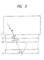
- k layers (where k is an integer) of optical thin film are successively formed on a transparent body T.
- the layers Moving successively outward from the transparent prism T, the layers are respectively designated as the first layer L1, second layer L2,.... . «k-th layer Lk.
- the surface of the j-th layer Lj which is facing the transparent prism T will be designated as the j-th surface
- the boundary surface (i.e. final surface) between the k-th layer Lk and the external air will be designated as the (k+1)-th surface.
- the overall reflectance, from the j-th surface to the final surface, is obtained by replacing the set of reflectances of that set of surfaces by that of a single equivalent surface, which will be referred to as the j-th equivalent surface.
- the following cumulative equations can be established for use in iterative calculations. Firstly, the reflectance of the final surface is obtained, then the reflectance for the k-th equivalent surface, and so on successively, using iterative calculations to sequentially obtain values of reflectance for each of the equivalent surfaces, up to the first equivalent surface.
- the value of reflectance thus obtained for the first equivalent surface is the reflectance for the entire multi-layer optical thin film.
- phase change which occurs in the S polarization component at total reflection from the final surface will be designated as ⁇ k+1,s , and the corresponding phase change of the P polarization component as ⁇ k+1,p .
- S 2 n k 2 sin 2 ⁇ k - 1 n k cos ⁇ k tan ⁇ k+1
- P 2 n k n k 2 sin 2 ⁇ k - 1 cos ⁇ k
- ⁇ j designates the change in phase of light rays which make one return journey between the j-th surface and the (j + 1)-th surface.
- n j the refractive index of the j-th layer
- d j the thickness of each layer
- ⁇ j the refraction angle of light rays which propagate from the j-th surface towards the (j + 1)-th surface
- ⁇ j the wavelength of light waves in air as ⁇
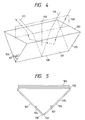
- a polarization plane rotator according to the present invention will now be described, referring to Fig. 4, which is an oblique general view of the embodiment.
- This consists of a prism 101 having the form described above referring to Fig. 1, i.e. having a triangular cross-sectional shape consisting of a right angle with the remaining two angles being mutually equal.
- the lateral surface which connects the apexes of the two equal angles is designated as the first surface 102, and the remaining two lateral surfaces are designated as the second surface 103 and third surface 104.
- the prism 101 is formed of glass, having a refractive index of 1.52, and the external medium is air.
- Fig. 5 is a cross-sectional view of this embodiment, taken in a plane perpendicular to the surfaces 102, 103, 104.
- the first surface 102 has a three-layer optical thin film 105 formed thereon, to reduce reflection of the S and P polarization components of incident light. These layers will be designated as the first layer, second layer and third layer respectively, proceeding successively outward from the surface 102.
- the second surface 103 and third surface 104 have respective single-layer optical thin films 106, 107 formed thereon, for reducing the phase difference ⁇ between the P and S polarization components as described hereinabove.
- the configuration of the multi-layer optical thin film 105 formed on the first surface 102 is shown in Table 1 below, while the configuration of each of the films 106, 107 formed on the second surface 103 and third surface 104 respectively, is shown in the Table 2 below.
- the plane 109 which passes through the line of intersection between the second surface 103 and third surface 104 and is perpendicular to the first surface 102, will be designated as the reference plane.
- Numeral 110 denotes an axis of incident light which is within the reference plane 109
- 111 denotes the axis of the resultant light that is emitted from the first surface 102, which is also within the reference plane 109.
- a light ray which is incident on the first surface 102 and is parallel to the axis 110 is diffracted at the first surface 102, then is incident on the second surface 103 or the third surface 104. If the light ray is incident on the second surface 103, it is then reflected at that surface and is then reflected by the third surface 104, to be again refracted at the first surface 102, with the resultant emitted light ray being parallel to the emitted light axis 111.
- a light ray which is incident on the third surface 104 will be reflected at that surface and then reflected by the second surface 103, to be again refracted at the first surface 102, with the resultant emitted light ray being parallel to the emitted light axis 111. From the above equations (1) and (8), it is found that when such a light ray is incident on the boundary surface 103 between the prism 101 and the optical thin film 106, the angle of incidence is 51.2°.
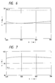
- the wavelength dependency of the relative phase difference ⁇ for the reflections at the surfaces 103, 104 i.e. phase difference between the S and P components of the emitted light from the prism, assuming that the corresponding phase difference of the incident light is 0 o
- the corresponding characteristic for the case in which the optical thin films 106, 107 are not formed on the second surface 103 and third surface 104 is shown by the broken-line curve in Fig. 6.
- phase difference ⁇ is made small, and varies only slightly in accordance with the wavelength of the light.
- the wavelength dependency of the phase difference merit factor ⁇ E is illustrated by the full-line curve in Fig. 7, while the corresponding characteristic for the case in which the optical thin films 106, 107 are not formed on the second surface 103 and third surface 104 is shown by the broken-line curve in Fig. 7.
- Fig. 7 there is a very substantial improvement in the phase difference merit factor ⁇ E as a result of forming the optical thin films 106 and 107, while the degree of wavelength dependency of that merit factor ⁇ E is small.
- the incident light rays on the first surface 102 are parallel to the incident light axis 110 and have a plane of polarization that is perpendicular to the reference plane 109, then due to the successive rotations of the plane of polarization which occur at the two total reflections (at the surfaces 103 and 104), the resultant light rays which are emitted to the exterior from the first surface 102 will have a plane of polarization that is close to being parallel to the reference plane 109.
- the S and P polarization components since one of these components is incident on the first surface 102 and the other component is subsequently emitted from the first surface 102, it is essential to achieve high values of transmittance for each of the polarization components Ts and Tp respectively of the S and P components, at the surface 102. If the first surface 102 is exposed to the air, and the angle of incidence of light falling on that surface is 45°, then since that angle is close to the Brewster's angle (56.7°), Tp will be very high, however Ts will not be high. For that reason a three layer optical thin film 105 is formed on the surface 102, by evaporative deposition, as an anti-reflection coating. Fig.
- the polarization plane rotator can convert linearly polarized light having a plane of polarization that is parallel to the reference plane 109 into linearly polarized light in which the plane of polarization is close to being perpendicular to the reference plane 109.
- the prism 101 and each of the optical thin films 105, 106, 107 should preferably each be capable of withstanding high temperatures, so that the the polarization plane rotator will be capable of high-temperature operation. In that case, the polarization plane rotator can be positioned closely adjacent to a powerful source of light.
- the apex angle between the second surface 103 and third surface 104 will differ slightly from 90 o .
- the light emitted from the prism 101 will consist of two different beams of light. If the angle is greater than 90 o , then these two beams will gradually diverge as they propagate through the air, whereas if the apex angle is less than 90 o then the two beams will mutually overlap, after having propagated through a certain distance.
- Fig. 10 is an oblique view of a second embodiment of a polarization plane rotator according to the present invention.
- This is formed of a transparent plate 121 and plurality of small, narrow elongated triangular transparent prism elements 122 which are arrayed mutually parallel at regular spacings on one surface of the transparent plate 121.
- the transparent plate 121 and the prism elements 122 are each formed of optical glass, and are mutually attached by a transparent adhesive material 123.
- Each of the prism elements 122 has a similar configuration to the prism 101 of the first embodiment, with the two inclined surfaces 126, 127 of each prism element 122 having identical areas and intersecting at a right angle, and sloping at identical angles of inclination to the surface of the transparent plate 121 on which they are mounted.
- the transparent plate 121 and each of the prism elements 122 has a refractive index that is close to 1.52.
- a three layer optical thin film 125 is formed as an anti-reflection coating, by evaporative deposition, on the surface 124 of the transparent plate 121 which is on the opposite side of that plate from the prism elements 122.
- double-layer optical thin films 128 are formed by evaporative deposition on the external surfaces 126, 127 of each of the prism elements 122, to ensure that the phase difference between polarization components of light reflected internally at these surfaces will be sufficiently small, as described hereinabove.
- the configuration of the optical thin film 125 is identical to that shown in Table 1 above, while the configuration of the optical thin film 128 is shown in the Table 3 below.
- ⁇ 2 51.2° Item Material Refractive Index Thickness (nm) Prism Glass 1.52 -- first layer SiO 1.70 102.5 second layer MgF 2 1.39 171.9 External medium Air 1.00 --
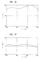
- the wavelength dependency of the phase difference ⁇ for the surfaces 126, 127 of each of the prism elements 122 is shown in Fig. 12, while the wavelength dependency of the phase difference merit factor ⁇ E is shown in Fig. 13.
- Fig. 12 The wavelength dependency of the phase difference ⁇ for the surfaces 126, 127 of each of the prism elements 122 is shown in Fig. 12, while the wavelength dependency of the phase difference merit factor ⁇ E is shown in Fig. 13.
- the action performed by the embodiment of Fig. 10 is identical to that of the embodiment of Fig. 4 described hereinabove.
- the external dimensions of the array of prism elements 122 is 30 mm (vertical) by 60 mm (horizontal), and the pitch of the prism elements 122 is 7 mm. It can thus be understood that the configuration of this embodiment enables the polarization plane rotator to be made thinner and lighter than is possible with that of Fig. 4, while in addition the internal optical path along which a light ray propagates within the polarization plane rotator can be made substantially shorter than in the case of the embodiment of Fig. 4.
- the transparent adhesive material 123 for example the KE1051 material manufactured by the Shin-Etsu Chemical Co., Ltd.
- the KE1051 material is supplied as two separate liquid materials, which when mixed, harden as a gel, if left at room temperature or if heated.
- the maximum usable temperature of such an adhesive material is 200° C.
- Fig. 14 shows the configuration of a third embodiment of a polarization plane rotator according to the present invention.
- This embodiment is basically similar to that of Fig. 10 described above, and for that reason is shown only in partial cross-sectional view in Fig. 14.
- This embodiment differs from that of Fig. 10 in that the polarization plane rotator is formed integrally from a single plate of glass, which will be referred to as the prism plate 131.
- the prism plate 131 is formed with a plane front surface 134 having an optical film 132 deposited thereon, and has the opposite surface formed with an array of small elongated triangular prism elements 135, disposed mutually parallel at regular spacings.
- the surfaces 137 of these prism elements 135 have deposited thereon an optical thin film 133.
- the glass of the prism plate of this embodiment has a refractive index of 1.52.
- the prism plate 131 can be formed to the required shape by using a mold having internal surfaces shaped with a suitable zig-zag contour, and pressing a thermally softened glass plate or glass block into the mold. If any surface irregularities such as small dents are left on the plane surface 134 after such a molding operation, these are removed by polishing, to form a flat surface.
- the optical thin film 132 is formed by evaporative deposition on the plane surface 134 as an anti-reflection coating, and has the configuration shown in the Table 1 above.
- the optical thin films 133, formed on the plane surfaces 137 of the prism elements 135 to reduce the internal reflection phase difference at these surfaces as described hereinabove, is a three-layer optical thin film formed by evaporative deposition, and has the configuration shown in the Table 4 below.
- ⁇ 2 51.2° Item Material Refractive Index Thickness (nm) Prism Glass 1.52 -- First layer Y 2 O 3 1.78 86.6 Second layer ZrTiO 4 2.10 66.1
- the wavelength dependency of the phase difference ⁇ for the surfaces 137 is shown in Fig. 15, while the wavelength dependency of the phase difference merit factor ⁇ E is shown in the graph of Fig. 16. Comparing Figs. 16 and 13, it can be seen that the wavelength dependency of the phase difference merit factor ⁇ E is made more flat when a three-layer optical thin film is formed on the surfaces of the prism elements, than when a double-layer optical thin film is used.
- a fourth embodiment of a polarization plane rotator according to the present invention will be described, which has an identical configuration to the embodiment of Fig. 14, and differs from the embodiment of Fig. 14 only with respect to the optical thin film 133.
- the configuration of the optical thin film 133 of the fourth embodiment is shown in the Table 5 below.
- the value of ⁇ 2 at the main wavelength is 2 ⁇ for the second layer.
- incorporation of such an intermediate layer, between other layers each having a thickness equivalent to ⁇ enables the wavelength dependency of the phase difference ⁇ to be reduced.
- ⁇ 2 51.2° Item Material Refractive Index Thickness (nm) Prism Glass 1.52 -- First layer Y 2 O 3 1.78 101.4 Second layer ZrTiO 4 2.10 144.2 Third layer MgF 2 1.39 171.9 External medium Air 1.00 --
- a fifth embodiment of a polarization plane rotator according to the present invention will be described, which has a similar configuration to that shown in Fig. 14, but differs in the configurations of the optical thin films 132, 133, and in that the prism plate 131 of the fifth embodiment is formed of glass which has a refractive index of 1.71.
- the configurations of the optical thin films 132 and 133 of this embodiment are shown in the Table 6 and Table 7 below, respectively.
- Fig. 19 shows the incident angle dependency of the polarisation plane rotation merit factor ⁇ R for this embodiment. As shown, that factor ⁇ R reaches its maximum value of 1 when the angle of incidence ⁇ 1 is 45 o .
- Fig. 20 shows the wavelength dependency of the internal reflection phase difference ⁇ for the prism surfaces 137, and the wavelength dependency of the phase difference merit factor ⁇ E is shown in Fig. 21. Comparing Figs. 21 and 16, it can be seen that if the refractive index of the prism plate 131 is high, as is the case with the fifth embodiment, then even if the optical thin film formed on the surfaces of the prism elements 135 consists of only two identical layers, the phase difference merit factor ⁇ E will be high.
- Fig. 22 shows the respective forms of wavelength dependency of the transmittance Ts of the S polarization component, the transmittance Tp of the P polarization component, and the product (Ts Tp) of these transmittances, for the front surface 134 of the prism plate 131 of the fifth embodiment. It can be understood from Fig. 22 that the transmittance of the front surface 134 can made substantially high.
- the prism plate 131 can be shaped by compression forming. If the maximum operating temperature of the polarization plane rotator will be no higher than 80 o C, then acrylic resin material is suitable. If the prism plate 131 is shaped by a molding process alone, there could be problems with regard to the accuracy of flatness of the surfaces of the prism elements 135. However since the intended applications of such a polarization plane rotator do not include image formation, the requirements for accuracy of the prism elements 135 are not very severe, so that in practice no problems would arise.
- a transparent resin for example acrylic resin, polycarbonate resin, etc.
- the plane surface 134 of the prism plate 131 it is possible for the plane surface 134 of the prism plate 131 to be joined to another transparent prism. If that is done, then the necessary value of angle between the incident and emitted light can be changed.
- FIG. 23 This is an oblique view of the embodiment, which consists of a polarizing beam splitter 141 and a pair of polarization plane rotators 142 and 143.
- the polarizing beam splitter 141 is a combination of three right-angle optical prisms, i.e. a central prism 144 and two outer prisms 145, 146, and two multi-layer optical thin films 147, 148 which are respectively formed by evaporative deposition on respective surfaces of the prism 144, 146.
- the prisms 144, 145 and 146 are arranged such that the optical thin films 147, 148 are sandwiched between opposing surfaces of the central prism 144 and the outer prisms 145, 146.
- Each of the prisms 144, 145, 146 is formed of glass, having a refractive index of 1.52.
- ⁇ G 45.0° Item Material Refractive Index Thickness (nm) Prism Glass 1.52 -- 1st layer MgF 2 1.39 56.7 2nd layer Y 2 O 3 1.78 88.5 3d layer MgF 2 1.39 113.3 4th layer Y 2 O 3 1.78 88.5 5th layer MgF 2 1.39 113.3 6th layer Y 2 O 3 1.78 88.5 7th layer MgF 2 1.39 113.3 8th layer Y 2 O 3 1.78 88.5 9th layer MgF 2 1.39 113.3 10th layer Y 2 O 3 1.78 88.5 11th layer MgF 2 1.39 113.3 12th layer Y 2 O 3 1.78 88.5 13th layer MgF 2 1.39 113.3 14th layer Y 2 O 3 1.78 123.9 15th layer MgF 2 1.39 158.6 16th layer Y 2 O 3 1.78 123.9 17th layer MgF 2 1.39 158.6 18th layer Y 2 O 3 1.78 123.9 19th layer MgF 2 1.39 158.6 20th layer
- each of the multi-layer optical thin films 147, 148 is formed as a succession of alternating layers of magnesium fluoride (having a refractive index of 1.39) and yttrium trioxide (having a refractive index of 1.78).
- Such an optical thin film has the property of transmitting the P polarization component of light which is incident thereon, and reflecting the S polarization component of that light.
- the surfaces of the polarizing beam splitter 141 which are exposed to the air i.e. the surfaces 149, 150, 151, 152 and 153, each have an anti-reflection coating formed thereon by evaporative deposition, consisting of an optical thin film having the configuration shown in the Table 9 below.
- ⁇ 1 0.0 o Item Material Refractive Index Thickness (nm) Prism Glass 1.52 -- First layer Al 2 O 3 1.62 78.7 Second layer ZrTiO 4 2.10 121.4 Third layer MgF 2 1.39 91.7 External medium Air 1.00 --
- Fig. 24 shows the wavelength dependency of the respective transmittances of the S and P polarization components, for the polarizing beam splitter 141.
- the transmittance for the P polarization component and the reflectance for the S polarization component do not attain respective ideal maximum values of 100%, however as can be understood from Fig. 24, they are close to the maximum values throughout the range of wavelengths shown.
- Each of the polarization plane rotators 142, 143 has the same configuration as that shown in Fig. 14.
- the respective surfaces 155, 156 of these polarization plane rotators which are on the side facing the polarizing beam splitter 141 are flat planes, while the other side of each of the polarization plane rotators 142, 143 is formed with an array of small prism elements 157, 158.
- the flat surfaces 155, 156 are oriented respectively parallel to the optical thin films 147, 148 of the polarizing beam splitter 141.
- Fig. 25 is a plan view of a second embodiment of a polarization converter according to the present invention.
- This embodiment consists of a two polarizing beam splitters 161, 162, and two polarization plane rotators 163, 164.
- the polarizing beam splitters 161, 162 are mutually identical, and so only the configuration of the polarizing beam splitter 161 will be described.
- This consists of two transparent plates 165, 166 and a multi-layer optical thin film 167.
- Each of the transparent plates 165, 166 is formed of glass having a refractive index of 1.71, and has a flat surface 168, 169 on one side thereof and an array of small elongated prism elements 170, 171 formed mutually parallel at regular spacings on the other side thereof.
- the surfaces 172, 173 of the prism elements 170, 171 respectively are each aligned at an angle of 45 o to the corresponding flat surface 168, 169.
- the prism elements 170, 171 are formed in the transparent plates 165, 166 by molding, as described hereinabove, using a thermally softened glass plate or glass block and a mold having zig-zag internal surface contours. For the reasons described hereinabove, it is not essential for the prism elements 170, 171 to be formed to an extremely high degree of accuracy.
- the multi-layer optical thin film 167 which transmits the P polarization component and reflects the S polarization component, is formed on the flat surface 168 of the transparent plate 165, and has the configuration shown in the Table 10 below.
- Each of the prism elements surfaces 172, 173 has formed thereon an optical thin film functioning as an anti-reflection coating, having the configuration shown in Table 11 below.
- the two transparent plates 165, 166 are mutually attached by a transparent adhesive material 174, eg silicone resin, with the flat surfaces 168, 169 mutually adjacent, and with the prism elements 170, 171 aligned mutually parallel.
- the other polarizing beam splitter 162 has an identical configuration to the polarizing beam splitter 161 described above.
- the two polarizing beam splitters 161, 162 are disposed with the multi-layer optical thin films 167, 175 aligned in a V-configuration forming a right angle, as seen in plan, with the apex of that V-shape being pointed in the opposite direction to the propagation direction of a beam of incident natural light.
- Fig. 26 shows the wavelength dependency of the respective transmittances for the P and S polarization components, for each of the polarizing beam splitters 161, 162.
- Each of the polarization plane rotators 163, 164 has the identical configuration shown in Fig. 10, described hereinabove. Respective flat surfaces 176, 177 of the polarization plane rotators 163, 164 are positioned opposing the polarizing beam splitters 161, 162 respectively, with the respective prism element arrays being designated as 178, 179. The flat surfaces 176, 177 are respectively aligned parallel to the multi-layer optical thin films 167, 175 of the polarizing beam splitters 161, 162 respectively.
- the S polarization component of the light emitted from the polarizing beam splitters 161 is incident on the flat surface 176 of the polarization plane rotator 163, while the S component from the polarizing beam splitters 162 is incident on the surface 177 of polarization plane rotator 164.
- the S component undergoes two total reflections within the prism elements 178, 179, to be then emitted from the flat surfaces 176, 177 of the polarization plane rotators 163, 164.
- the linearly polarized light which is propagated through the polarizing beam splitters 161, 162 and emitted therefrom and the linearly polarized light which is emitted from the polarization plane rotators 163, 164 have the respective planes of polarization and directions of propagation mutually parallel. It can thus be understood that this embodiment provides highly efficient conversion of natural light into light which is close to a condition of being completely linearly polarized.
- n H is the refractive index of the layers having a high refractive index
- n L is that of the layers having a low refractive index
- n G is the refractive index of the prism
- ⁇ G is the angle of incidence on the multi-layer optical thin film of light which exits from the prism.
- the transparent plates of the polarizing beam splitter are thin in shape, then it is possible to use a molding process as described above for forming the prism elements of the polarizing beam splitter, and this further serves to ensure that the overall manufacturing cost of the polarization converter of Fig. 25 can be low.
- Fig. 27 is a general cross-sectional view in plan of an embodiment of a polarized light source according to the present invention.
- Numeral 202 denotes a halogen lamp
- 203 denotes a concave mirror formed of aluminum.
- Light emitted from the lamp 202 is converted to a directional beam by the concave mirror 203, to be incident on a polarization converter 204.
- the polarization converter 204 is identical to the polarization converter embodiment shown in Fig. 25.
- a beam of natural light 205 reflected from the concave mirror 203 is converted to light 206, which is close to being in a linearly polarized condition and is emitted from the polarization converter 204.
- Such a polarized light source can be effectively used in a light source for various applications. These include illumination applications, for video or still photography. If natural light is used for such illumination, then if the illuminating light falls obliquely on a subject being photographed, some of the light may be strongly reflected from parts of the subject, causing these parts to glitter conspicuously.
- This problem can be overcome by using linearly polarized light to illuminate the subject. In that case, the direction of the plane of polarization can be adjusted such as to minimize the glitter. This is due to the fact that the reflectance for the S polarization component and P polarization component of the light will vary, over different regions of the subject.
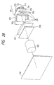
- a light source 211 consists of a lamp 212, a concave mirror 213, and a filter 214.
- the lamp 212 is a metal halide lamp which emits natural light containing the three primary colors as color components.
- the concave mirror 213 is formed of glass having the inner (i.e. reflecting) surface thereof formed in a parabolic shape.
- a multi-layer optical thin film is formed by evaporative deposition over the inner surface of the concave mirror 213, with the multi-layer optical thin film being configured such as to transmit infra-red radiation and to reflect visible light rays.
- the filter 214 is a glass plate having a multi-layer optical thin film formed thereon by evaporative deposition. That multi-layer optical thin film is configured to transmit visible light rays and to reflect ultra-violet and infra-red radiation.
- the optical axis 216 of the concave mirror 213 is aligned horizontally, and the central axis of the lamp 212 (which is of elongated tubular shape) is oriented along the optical axis 216.
- the light emitted from the lamp 212 is reflected by the concave mirror 213, and converted to a light beam which is closely parallel, with the infra-red radiation components substantially removed, then passes through the filter 214 which removes the ultra-violet radiation component and any remaining infra-red radiation, leaving only visible light to be emitted from the light source 211. That light is then incident on a polarization converter 220.
- the configuration of the polarization converter 220 is identical to the embodiment of Fig. 25, described hereinabove, being formed of two polarizing beam splitters 221, 222, and two polarization plane rotators 223, 224.
- the polarization converter 220 converts the natural light which is emitted from the light source 211 into light that is close to being in a linearly polarized condition.
- the linearly polarized light thus emitted from the polarization converter 220 is transmitted through a field lens 227, to then be incident on a liquid crystal panel 228, which functions as a light valve.
- the liquid crystal panel 228 of this embodiment is a TFT (thin-film transistor) liquid crystal panel which utilizes TN liquid crystal, and which has built-in color filters.
- the transmittance of the liquid crystal panel 228 is varied in accordance with a video signal, such as to form a full-color optical image, and the light thus emitted from the liquid crystal panel 228 is transmitted through a projection lens 229, to projected the optical image as an enlarged picture on a projection screen 230 which is spaced at some distance from the projection lens 229.
- the liquid crystal panel 228 consists of an incidence side polarizing plate, a liquid crystal panel, and an emission side polarizing plate (not shown in the drawings).
- the polarization axis of the incidence side polarizing plate is directed in the horizontal direction of the picture.
- the transmittance of the incidence side polarizing plate is high, and the optical efficiency of the projection display system is substantially improved by comparison with the prior art.
- the amount of light energy that is absorbed by the incidence side polarizing plate is small, thereby ensuring that the incidence side polarizing plate exhibits only a small increase in temperature. Hence, the reliability of that polarizing plate is increased.
- the polarization plane rotators 223, 224 are oriented such that the reflected light beams from the polarization plane rotators 223, 224 and the propagated light beam from the polarizing beam splitters will all be mutually parallel, in general in a practical apparatus it may be preferable to ensure that the light rays reflected from the polarization plane rotators 223, 224 converge, at a predetermined angle, towards the central axis of the light rays propagated through the polarizing beam splitters 221, 222. That can be accomplished, for example with the embodiment of Fig.
- the liquid crystal panel 228 of this embodiment is configured to provide a display picture having a large value of aspect ratio, for example the ratio 16(horizontal):9(vertical) which is necessary with the Hi-Vision television standard.
- a polarized light source in accordance with the present invention is particularly advantageous when applied to illuminate a light valve which has a large value of aspect ratio, by comparison with prior art types of polarized light source. The reason for this lies in the fact that the polarized light that is produced is a combination of a central beam (propagated through the polarizing beam splitters 221, 222) and two side beams (reflected from the polarization plane rotators 223, 224).
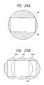
- the illumination pattern will be identical to the cross-sectional shape of an original light beam, i.e. will be of circular cross-section.
- numeral 300 designates the effective display region of a light valve having a large value of aspect ratio, e.g. 16:9, while the hatched-line region 301 designates the part of the illumination light (from a beam of linearly polarized light having a circular cross-sectional shape) applied to the light valve, which is not utilized.
- Fig. 29A designates the effective display region of a light valve having a large value of aspect ratio, e.g. 16:9
- the hatched-line region 301 designates the part of the illumination light (from a beam of linearly polarized light having a circular cross-sectional shape) applied to the light valve, which is not utilized.
- the circular region 304 denotes an area of illumination on the light valve display region 300 that is constituted by light propagated through the polarizing beam splitters 221, 222, while the two semicircular regions 302a, 302b denote the areas of illumination constituted by light reflected from the polarization plane rotators 223, 224, respectively.
- the polarized light source 220 is configured (as described hereinabove) such that the light beams reflected from the polarization plane rotators 223, 224 will mutually converge, with the amount of convergence at the position of the light valve being determined such as to produce a certain amount of overlap between the light that is provided from the polarization plane rotators 223, 224 and the light that is provided from the polarizing beam splitters 221, 222. It will be clear that, if necessary, various methods could be adopted to ensure that the overall intensity of illumination on the light valve will be substantially uniform, in spite of the regions of illumination overlap.
- the proportion of incident light on the light valve which is effectively used will be substantially greater than in the case of using a prior art type of polarized light source, so that the light utilization efficiency of the projection display system is enhanced.
- This is a significant advantage of a polarized light source according to the present invention, when used to produce a projected display picture having a large value of aspect ratio.
- the axis of polarization of the incidence side polarizing plate of the light valve may be aligned at an angle of 45 o to the vertical direction of the display picture.
- a polarizing light source according to the present invention can be utilized if a half-wave plate is disposed at the incidence side of the incidence side polarizing plate, with the direction of a fast axis (a phase advance axis) or a slow axis (a phase retardation axis) of the half-wave plate being inclined at an angle of 22.5 o relative to the vertical direction of the display picture, to thereby maximize the amount of light which will be transmitted through the incidence side polarizing plate.
- Fig. 30 is a general cross-sectional view in elevation of a second embodiment of a projection display system according to the present invention.
- the light source 231 is configured identically to the light source 211 of the embodiment of Fig. 28 described above, consisting of a lamp 232, a concave mirror 233 and a filter plate 234. Natural light emitted from the lamp 232 is converted by the concave mirror 233 to a substantially parallel beam, with the infra-red rays removed, and the ultra-violet rays and remaining infra-red rays are removed by the filter 234, which transmits only visible natural light rays.
- the light from the filter 234 falls on a polarization converter 240, which has the same configuration as that shown in Fig.
- the natural light transmitted through the filter 234 is thereby converted to light which is substantially close to being in a linearly polarized condition, with the polarizing plane being vertical to the plane of the paper, as viewed in Fig. 30.
- the linearly polarized light from the polarization converter 240 is incident on polarization selective mirrors 247, 248 and on a plane mirror 249, which constitute a color separating optical system for separating the red, green and blue primary color components of the light. These primary color components then pass through respective field lenses 250, 251 and 252, and are then incident on respective liquid crystal panels 253, 254 and 255.
- Each of the liquid crystal panels 253 to 255 is a TFT liquid crystal panel, utilizing TN liquid crystal, and changes in transmittance in accordance with a video signal, to form an optical image.
- the resultant light emitted from the liquid crystal panels 253, 254, 255 is combined into a single light beam by a color combining optical system which is a combination of polarization selective mirrors 256, 257 and a plane mirror 258.
- the combined light is then incident on a projection lens 259, to be projected onto a projection screen (not shown in the drawing) that is spaced at a distance from the projection lens 259, to form an enlarged display picture.
- Each of the liquid crystal panels 253, 254, 255 is formed of an incidence side polarizing plate, a liquid crystal panel, and an emission side polarizing plate.
- the polarization axis of the incidence side polarizing plate is directed in the horizontal direction of the picture (which is perpendicular to the paper plane, as seen in Fig. 30).
- the transmission coefficient of the incidence side polarizing plate is high, and the optical efficiency of the projection display system is high.
- the amount of light energy that is absorbed by the incidence side polarizing plate is small, thereby ensuring that the incidence side polarizing plate only has a small increase in temperature, so that the reliability of that polarizing plate is increased.
- the second projection display system embodiment is highly advantageous when configured to produce a display picture having a large value of aspect ratio, such as 16:9, since the proportion of the polarized light which is effectively incident on the display regions of each of the liquid crystal panels 253, 254, 255 is substantially increased, by comparison with a projection display system utilizing a prior art type of polarized light source.
- the polarization converter 240 is positioned between the light source 231 and the color analyzing optical system.
- the temperature at which each of these polarization converters must operate would be substantially lower than is required for the polarization converter 240 in Fig. 30, it would be possible to form the polarization converters from an inexpensive material having a relatively low resistance to heat.
- a light valve which is a TFT liquid crystal panel, utilizing TN liquid crystal.
- other types of light valve for example liquid crystal panels using other types of liquid crystal, or devices using a material such as electro-optical crystal whereby an optical image is formed by changes in the double refraction characteristic.
- a polarization converter according to the present invention is applicable to any type of projection display system which utilizes a light valve having at least an incidence side polarizing plate.
- the present invention provides a polarization plane rotator which can be compact in size and can be configured to exhibit only a small degree of dependency of its characteristics upon wavelength.
- the invention further provides a polarization converter whereby natural light is efficiently converted to light which is substantially close to being in a linearly polarized condition.
- a polarized light source can be provided which has a high degree of light utilization efficiency, and as a result, a projection display system can be provided which has a high degree of light utilization efficiency.
Landscapes
- Physics & Mathematics (AREA)
- Engineering & Computer Science (AREA)
- Multimedia (AREA)
- Signal Processing (AREA)
- General Physics & Mathematics (AREA)
- Optics & Photonics (AREA)
- Chemical & Material Sciences (AREA)
- Crystallography & Structural Chemistry (AREA)
- Polarising Elements (AREA)
- Projection Apparatus (AREA)
- Liquid Crystal (AREA)
Claims (23)
- Dispositif rotateur de plan de polarisation comprenant un moyen destiné à générer un premier faisceau de lumière incidente polarisée pratiquement linéairement se propageant à l'intérieur d'un milieu gazeux le long d'une direction de lumière incidente et présentant un premier plan de polarisation, et un rotateur de plan de polarisation (101) disposé à l'intérieur dudit milieu gazeux afin de convertir ledit premier faisceau en un faisceau émis de lumière émise polarisée pratiquement linéairement se propageant le long d'une direction de lumière émise qui est substantiellement différente de ladite direction de lumière incidente, ledit faisceau de lumière émise présentant un plan de polarisation qui est tourné d'un angle de pratiquement 90° par rapport audit premier plan de polarisation, le rotateur de polarisation comprenant un prisme transparent présentant une forme en section transversale sous forme d'un triangle isocèle et présentant une première surface de plan (102) qui relie les sommets respectifs de deux angles égaux dudit triangle et une seconde surface de plan (103) ainsi qu'une troisième surface de plan (104), ledit prisme transparent étant orienté avec un plan de référence (109) de celui-ci disposé pratiquement parallèlement à ladite direction de lumière incidente et ladite direction de lumière émise, ledit plan de référence étant défini comme un plan qui comprend une droite d'intersection desdites seconde et troisième surfaces de plan et recoupe ledit prisme de façon symétrique, ledit plan de référence étant orienté pratiquement parallèlement ou perpendiculairement audit plan de polarisation connu,caractérisé en ce que :ledit prisme (101) étant orienté par rapport audit premier faisceau de lumière de telle manière que ledit premier faisceau intercepte ladite première surface de plan (102) suivant un angle d'incidence oblique particulier, etledit angle d'incidence oblique étant prédéterminé par rapport à l'indice de réfraction du matériau constituant ledit prisme transparent de telle manière que ledit premier faisceau soit réfracté au niveau de ladite première surface de plan (102), subisse une première réflexion pratiquement totale au niveau de l'une de ladite seconde surface de plan (103) et de ladite troisième surface de plan (104), subisse une seconde réflexion pratiquement totale au niveau de l'autre de ladite troisième surface de plan (102) et de ladite seconde surface de plan (103), et soit ensuite réfracté au niveau de ladite première surface de plan (102) afin de sortir dudit prisme le long dudit axe de lumière émise,un film optique mince (106, 107) est formé sur chacune desdites seconde et troisième surfaces de plan (103, 104), ledit film optique mince (106, 107) présentant un indice de réfraction qui est inférieur à l'indice de réfraction du matériau constituant ledit prisme transparent (101).
- Dispositif rotateur de plan de polarisation selon la revendication 1, dans lequel lesdites seconde et troisième surfaces de plan (103, 104) sont de taille et de forme identiques.
- Dispositif rotateur de plan de polarisation selon la revendication 1 ou 2, dans lequel l'angle d'intersection entre lesdites seconde et troisième surfaces de plan (103, 104) est un angle droit.
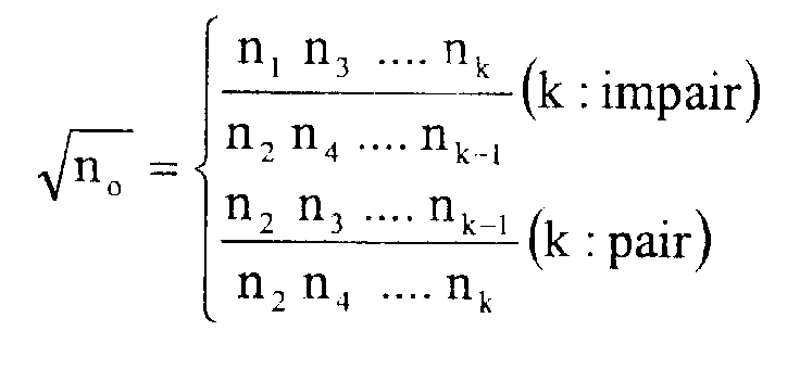
- Dispositif rotateur de plan de polarisation selon la revendication 1, 2 ou 3, dans lequel ledit film optique mince est un film optique mince multicouches (106, 107), comportant au moins deux couches, formées sur chacune desdites seconde et troisième surfaces de plan (103, 104), dans lequel en désignant un indice de réfraction dudit prisme transparent (101) par no, des couches successives dudit film optique mince multicouches s'étendant successivement depuis ledit corps transparent sous forme respectivement d'une première couche jusqu'à une kème couche, un indice de réfraction d'une jème couche parmi lesdites couches par nj et une épaisseur de ladite jème couche par dj, un angle de réfraction dans ladite jème couche par γj, et une longueur d'onde prédéterminée de la lumière dans l'air par λc, les conditions suivantes sont satisfaites :
- Dispositif rotateur de plan de polarisation selon la revendication 4, dans lequel ladite valeur k est égale à 2.
- Dispositif rotateur de plan de polarisation selon la revendication 4 ou 5, dans lequel ledit indice de réfraction de ladite kème couche est inférieur audit indice de réfraction dudit prisme transparent (101).
- Dispositif rotateur de plan de polarisation selon la revendication 4 ou 5, dans lequel ladite keme couche est formée de fluorure de magnésium.
- Dispositif rotateur de plan de polarisation selon la revendication 4, 5, 6 ou 7,et comprenant en outre un film optique mince présentant un indice de réfraction nj', une épaisseur dj' et un angle de réfraction ηj', ledit film optique mince étant formé entre une j'ème couche et une (j'-1)ème couche dudit film optique mince multicouches de base, où j' est un nombre entier quelconque supérieur à 1 et la condition suivante est satisfaite :
- Dispositif rotateur de polarisation selon l'une quelconque des revendications précédentes, dans lequel ledit rotateur de plan de polarisation comprend en outre une plaque de rotateur de plan de polarisation transparente comportant une surface plate (124) et présentant une surface opposée à ladite surface plate formée avec une pluralité de prismes transparents minuscules allongés (122) disposés en parallèle avec des espacements réguliers, chacun desdits prismes minuscules étant construit et orienté d'une manière similaire au rotateur de plan de polarisation défini dans l'une quelconque des revendications précédentes, les premières surfaces de plan desdits rotateurs de plan de polarisation correspondant à ladite surface opposée de ladite plaque de rotateur de plan de polarisation.
- Dispositif de rotateur de plan de polarisation selon la revendication 9, dans lequel ladite plaque de rotateur de plan de polarisation transparente constitue une unité intégrée qui a été formée par un procédé de formation utilisant un cule.
- Convertisseur de polarisation comprenant :un miroir de sélection de polarisation (141) destiné à séparer un faisceau de lumière non polarisée en un premier faisceau de lumière polarisée qui est très proche de la condition d'une polarisation linéaire dans une première direction de polarisation et un faisceau de lumière à une seconde polarisation qui est très proche de la condition de polarisation linéaire dans une seconde direction de polarisation qui est tournée de 90° par rapport à ladite première direction de polarisation, lesdits premier et second faisceaux de lumière polarisée présentant des directions respectives différentes de propagation, etune plaque de rotateur de plan de polarisation (142) tel que défini dans la revendication 9 ou 10, positionnée pour que ledit premier faisceau de lumière polarisée soit incident sur celle-ci afin de convertir ainsi ledit premier faisceau de lumière polarisée en un faisceau de lumière polarisée émise qui est polarisé pratiquement linéairement, la direction de polarisation ayant tourné de 90° par rapport à ladite direction de polarisation dudit faisceau de lumière de la première polarisation, ladite plaque de rotateur de plan de polarisation étant positionnée par rapport audit miroir (141) de telle manière que ledit faisceau de lumière polarisée émise et ledit second faisceau de lumière polarisée soient pratiquement parallèle l'un à l'autre.
- Convertisseur de polarisation comprenant :deux miroirs de sélection de polarisation (141), dont chacun est disposé en vue de séparer un faisceau de lumière non polarisée en deux faisceaux de lumière polarisée pratiquement linéairement, etdeux plaques de rotateurs de plan de polarisation (142, 143) telles que défini dans la revendication 9 ou 10, lesdits deux miroirs de sélection de polarisation (141) comportant des surfaces de réflexion (147, 148) de ceux-ci disposées suivant une configuration en V, lesdites plaques de rotateurs de plan de polarisation (142, 143) étant disposées parallèlement à des surfaces de réflexion respective (147, 148) desdits miroirs de sélection de polarisation, lesdits miroirs de sélection de polarisation (141) étant orientés par rapport audit faisceau de lumière non polarisée de telle manière qu'une première composante de polarisation de ladite lumière non polarisée soit transmise au travers desdits miroirs de sélection de polarisation et qu'une seconde composante de polarisation de ladite lumière non polarisée soit réfléchie par lesdits miroirs de sélection de polarisation sous forme des premier et second faisceaux de lumière polarisée qui sont incidents sur des rotateurs respectifs parmi lesdits rotateurs de plan de polarisation, d'où il résulte que chacun desdits premier et second faisceaux de lumière polarisée a son plan de polarisation tourné de 90° et son trajet lumineux modifié pour devenir pratiquement parallèle au trajet lumineux de ladite première composante de polarisation.
- Convertisseur de polarisation selon la revendication 11 ou 12, dans lequel un angle droit est formé entre la direction d'incidence et la direction d'émission du miroir ou de chaque miroir de sélection de polarisation (141),
- Convertisseur de polarisation selon la revendication 11 ou 12, dans lequel le miroir ou chaque miroir de sélection de polarisation (141) comprend un film optique mince multicouches (147) qui transmet une majeure parie de la composante à polarisation P de la lumière qui est incidente sur celui-ci, et réfléchit une majeure partie de la composante à polarisation S de ladite lumière incidente, et deux prismes triangulaires transparents (144, 145) comportant ledit film optique mince multicouches (147) pris en sandwich entre ceux-ci.
- Convertisseur de polarisation selon la revendication 14, dans lequel lesdits prismes triangulaires transparents (144, 145) sont chacun formés de verre.
- Convertisseur de polarisation selon la revendication 14 ou 15, dans lequel chacun desdits prismes triangulaires est formé d'un matériau présentant un indice de réfraction qui est au moins de 1,5 et ne dépasse pas 1,8.
- Convertisseur de polarisation selon la revendication 14, 15 ou 16, dans lequel lesdits deux prismes triangulaires (144, 145) sont fixés l'un à l'autre par une résine de silicone transparente.
- Convertisseur de polarisation selon la revendication 11, 12 ou 13, dans lequel le miroir ou chaque miroir de sélection de polarisation (161, 162) comprend un film optique mince multicouches (167, 175) qui transmet une majeure partie de la composante de polarisation P de la lumière qui est incidente sur celui-ci et réfléchit une majeure partie de la composante de polarisation S de ladite lumière incidente, et deux plaques transparentes (165, 166) présentant chacune une surface plate et comportant une surface opposée à ladite surface plate formée avec une pluralité de prismes minuscules allongés (170, 171) disposés parallèlement avec des espacements réguliers, ledit film optique mince multicouches (167, 175) étant pris en sandwich entre lesdites surfaces plates desdites plaques transparentes (165, 166).
- Convertisseur de polarisation selon la revendication 18, dans lequel chacune desdites plaques transparentes (165, 166) est formée d'un matériau présentant un indice de réfraction qui est au moins de 1,5, de préférence d'au moins 1,6, et ne dépasse pas 1,8.
- Convertisseur de polarisation selon la revendication 18 ou 19, dans lequel lesdites deux plaques transparentes (165, 166) sont fixées l'une à l'autre par une résine de silicone transparente.
- Source de lumière polarisée ccmprenant :une source de lumière (202, 203) qui émet un faisceau de lumière non polarisée, etun convertisseur de polarisation (204) selon l'une quelconque des revendications 11 à 20.
- Système de présentation de projection comprenant :une source de lumière polarisée (211) selon la revendication 21,une valve de lumière (228) sur laquelle est incidente de la lumière qui est émise à partir dudit rotateur de plan de polarisation (223, 224) et exécutant des modifications de rotation de polarisation ou de biréfringence conformément à un signal vidéo afin de produire une image optique, etun objectif de projection (229) sur lequel est incidente de la lumière qui est émise à partir de ladite valve de lumière (228), afin de projeter ladite image optique jusque sur un écran de projection (230).
- Système de présentation de projection comprenant :une source de lumière (231) qui émet un faisceau de lumière non polarisée contenant trois couleurs primaires sous forme de composantes de couleurs,un moyen de séparation de couleurs (247, 248, 249) destiné à séparer ledit faisceau de lumière non polarisée en trois faisceaux de lumière des couleurs primaires,trois valves de lumière (253, 254, 255) disposées pour que lesdits faisceaux de lumière des trois couleurs primaires soient respectivement incidents sur celles-ci, chacune desdites valves de lumière étant sensible à un signal vidéo afin d'exécuter des modifications de rotation de polarisation ou de biréfringence afin de former ainsi une image optique,un moyen de combinaison de couleurs (256, 257, 358) destiné à combiner des faisceaux de lumière émis à partir desdites valves de lumière (253, 254, 255) en un seul faisceau de lumière,un objectif de projection (259) sur lequel est incidente de la lumière qui est émise à partir desdites valves de lumière, afin de projeter lesdites images optiques formées par lesdites valves de lumière, jusque sur un écran de projection,un moyen de convertisseur de polarisation selon l'une quelconque des revendications 11 à 20, disposé au niveau du côté d'incidence dudit moyen de séparation de couleurs ou au niveau de positions intermédiaires à l'intérieur dudit moyen de séparation de couleurs, afin de convertir ladite lumière non polarisée en une lumière qui est polarisée pratiquement linéairement.
Applications Claiming Priority (6)
| Application Number | Priority Date | Filing Date | Title |
|---|---|---|---|
| JP32390792 | 1992-12-03 | ||
| JP32390792 | 1992-12-03 | ||
| JP323907/92 | 1992-12-03 | ||
| JP5003776A JPH06222212A (ja) | 1992-12-03 | 1993-01-13 | 偏波面回転光学装置及び偏光変換光学装置及び投写型表示装置 |
| JP3776/93 | 1993-01-13 | ||
| JP377693 | 1993-01-13 |
Publications (2)
| Publication Number | Publication Date |
|---|---|
| EP0600728A1 EP0600728A1 (fr) | 1994-06-08 |
| EP0600728B1 true EP0600728B1 (fr) | 1999-08-11 |
Family
ID=26337416
Family Applications (1)
| Application Number | Title | Priority Date | Filing Date |
|---|---|---|---|
| EP93309618A Expired - Lifetime EP0600728B1 (fr) | 1992-12-03 | 1993-12-01 | Rotateur de polarisation plan applicable à un convertisseur de polarisation et système d'affichage par projection |
Country Status (4)
| Country | Link |
|---|---|
| US (1) | US5657160A (fr) |
| EP (1) | EP0600728B1 (fr) |
| JP (1) | JPH06222212A (fr) |
| DE (1) | DE69325973T2 (fr) |
Cited By (1)
| Publication number | Priority date | Publication date | Assignee | Title |
|---|---|---|---|---|
| RU2184987C2 (ru) * | 1997-08-05 | 2002-07-10 | Денисов Александр Николаевич | Отражательная призма для поворота плоскости поляризации |
Families Citing this family (22)
| Publication number | Priority date | Publication date | Assignee | Title |
|---|---|---|---|---|
| US5606436A (en) * | 1994-11-21 | 1997-02-25 | Proxima Corporation | Liquid crystal projection panel construction and method of making same |
| DE19649229A1 (de) * | 1995-11-28 | 1997-06-05 | Hughes Aircraft Co | Polarisationsvorrichtung |
| US5751482A (en) * | 1996-04-22 | 1998-05-12 | Imation Corp. | Achromatic polarization-rotating right-angle prism system |
| AU6418398A (en) | 1997-03-25 | 1998-10-20 | Sharp Kabushiki Kaisha | A polarized-light converting optical system, a polarized-light converting elemental device, polarized-light converting elemental device array and projection-type display device using any one of those components |
| JPH11260141A (ja) * | 1998-03-11 | 1999-09-24 | Omron Corp | 偏光変換光学素子及び直線偏光回転方法 |
| US6995917B1 (en) | 1999-04-08 | 2006-02-07 | Sharp Laboratories Of America, Inc. | Projection display system using polarized light |
| US6373630B1 (en) | 2000-05-05 | 2002-04-16 | Chih-Kung Lee | Light beam polarization converter |
| US6396630B1 (en) * | 2001-03-16 | 2002-05-28 | Rose Research, Llc | Device and method for a folded transmissive phase retarder |
| US6511183B2 (en) * | 2001-06-02 | 2003-01-28 | Koninklijke Philips Electronics N.V. | Digital image projector with oriented fixed-polarization-axis polarizing beamsplitter |
| US20040256539A1 (en) * | 2002-03-19 | 2004-12-23 | Clay Joseph M. | Method and apparatus for converting or otherwise utilizing radiation pressure to generate mechanical work |
| US20040021940A1 (en) * | 2002-07-30 | 2004-02-05 | Gunther John E. | Optical polarization rotating device |
| JP2005326575A (ja) * | 2004-05-13 | 2005-11-24 | Ricoh Co Ltd | 偏光回転素子、偏光変換素子、照明装置及び画像表示装置 |
| US7306343B2 (en) | 2005-04-22 | 2007-12-11 | Hewlett-Packard Development Company, L.P. | Image rotator |
| EP2070101A4 (fr) * | 2006-07-26 | 2012-01-25 | Spacedesign Corp | Procédé et dispositif pour communiquer une pression de rayonnement fournie par une onde lumineuse |
| KR20150024416A (ko) * | 2012-06-27 | 2015-03-06 | 쓰리엠 이노베이티브 프로퍼티즈 컴파니 | 광학 컴포넌트 어레이 |
| CN104718468B (zh) * | 2012-11-08 | 2018-04-10 | 亚斯卡奈特股份有限公司 | 光控制面板的制造方法 |
| CN104777545B (zh) * | 2015-05-05 | 2018-05-01 | 武汉大学 | 一种硅纳米砖阵列偏振分光器 |
| US9989926B2 (en) * | 2016-02-19 | 2018-06-05 | Honeywell International Inc. | Systems and methods for positionally stable magneto-optical trapping over temperature |
| CN205787403U9 (zh) * | 2016-05-18 | 2017-04-26 | 颜栋卿 | 一种可提高光利用率的立体投影装置 |
| CN109149120B (zh) * | 2018-08-30 | 2024-01-30 | 南京信息工程大学 | 一种线极化波任意极化角度偏转器 |
| CN110927974B (zh) * | 2019-12-18 | 2022-05-10 | 业成科技(成都)有限公司 | 光学成像模组和vr电子设备 |
| CN110955052A (zh) * | 2019-12-18 | 2020-04-03 | 业成科技(成都)有限公司 | 光学成像模组和vr电子设备 |
Family Cites Families (26)
| Publication number | Priority date | Publication date | Assignee | Title |
|---|---|---|---|---|
| US2087329A (en) * | 1935-11-16 | 1937-07-20 | Spencer Lens Co | Microscope |
| US2887566A (en) * | 1952-11-14 | 1959-05-19 | Marks Polarized Corp | Glare-eliminating optical system |
| NL126444C (fr) * | 1963-04-22 | 1900-01-01 | ||
| US3879105A (en) * | 1974-04-04 | 1975-04-22 | Jenoptik Jena Gmbh | Telescope with an image reversing system |
| US4367949A (en) * | 1980-06-02 | 1983-01-11 | Lavering Gordon R | Aiming method and means |
| US4380076A (en) * | 1980-12-31 | 1983-04-12 | International Business Machines Corporation | Apparatus for four side transverse irradiation of a region |
| JPS57132114A (en) * | 1981-02-07 | 1982-08-16 | Olympus Optical Co Ltd | Dividing method of light flux |
| US4525034A (en) * | 1982-12-07 | 1985-06-25 | Simmons Clarke V | Polarizing retroreflecting prism |
| JPH0715537B2 (ja) * | 1985-12-05 | 1995-02-22 | セイコーエプソン株式会社 | 投写型表示装置 |
| US4709144A (en) * | 1986-04-02 | 1987-11-24 | Hewlett-Packard Company | Color imager utilizing novel trichromatic beamsplitter and photosensor |
| JPS63168622A (ja) * | 1987-01-05 | 1988-07-12 | Canon Inc | 光偏向素子 |
| JPS63197913A (ja) * | 1987-02-13 | 1988-08-16 | Nec Corp | 偏光変換素子 |
| US5237446A (en) * | 1987-04-30 | 1993-08-17 | Olympus Optical Co., Ltd. | Optical low-pass filter |
| JPS63271313A (ja) * | 1987-04-30 | 1988-11-09 | Nikon Corp | 偏光器 |
| US4822150A (en) * | 1987-05-18 | 1989-04-18 | Eastman Kodak Company | Optical device for rotating the polarization of a light beam |
| GB8720923D0 (en) * | 1987-09-05 | 1987-10-14 | Emi Plc Thorn | Optical image rotators |
| JPH0264522A (ja) * | 1988-08-31 | 1990-03-05 | Hitachi Ltd | 光変調器 |
| JP2744295B2 (ja) * | 1989-09-07 | 1998-04-28 | 富士通株式会社 | 偏波結合器 |
| US4979026A (en) * | 1989-03-07 | 1990-12-18 | Lang Paul W | Polarized light 360 degree viewing system |
| US4991938A (en) * | 1989-04-07 | 1991-02-12 | Gte Laboratories Incorporated | Quasi-achromatic optical isolators and circulators using prisms with total internal fresnel reflection |
| JP2893599B2 (ja) * | 1989-10-05 | 1999-05-24 | セイコーエプソン株式会社 | 偏光光源及び投写型表示装置 |
| EP0422661A3 (en) * | 1989-10-13 | 1992-07-01 | Mitsubishi Rayon Co., Ltd | Polarization forming optical device and polarization beam splitter |
| JPH03126910A (ja) * | 1989-10-13 | 1991-05-30 | Mitsubishi Rayon Co Ltd | 偏光光源装置及び偏光ビームスプリッター |
| JPH03132603A (ja) * | 1989-10-18 | 1991-06-06 | Matsushita Electric Ind Co Ltd | 偏光子 |
| US5132822A (en) * | 1990-11-29 | 1992-07-21 | Gte Laboratories Incorporated | Optical switch |
| US5223956A (en) * | 1992-03-30 | 1993-06-29 | Holotek Ltd. | Optical beam scanners for imaging applications |
-
1993
- 1993-01-13 JP JP5003776A patent/JPH06222212A/ja active Pending
- 1993-12-01 EP EP93309618A patent/EP0600728B1/fr not_active Expired - Lifetime
- 1993-12-01 DE DE69325973T patent/DE69325973T2/de not_active Expired - Fee Related
- 1993-12-03 US US08/160,751 patent/US5657160A/en not_active Expired - Fee Related
Cited By (1)
| Publication number | Priority date | Publication date | Assignee | Title |
|---|---|---|---|---|
| RU2184987C2 (ru) * | 1997-08-05 | 2002-07-10 | Денисов Александр Николаевич | Отражательная призма для поворота плоскости поляризации |
Also Published As
| Publication number | Publication date |
|---|---|
| EP0600728A1 (fr) | 1994-06-08 |
| US5657160A (en) | 1997-08-12 |
| DE69325973D1 (de) | 1999-09-16 |
| JPH06222212A (ja) | 1994-08-12 |
| DE69325973T2 (de) | 2000-04-06 |
Similar Documents
| Publication | Publication Date | Title |
|---|---|---|
| EP0600728B1 (fr) | Rotateur de polarisation plan applicable à un convertisseur de polarisation et système d'affichage par projection | |
| TWI516805B (zh) | 光學元件、色彩合成器及投影系統 | |
| US7369186B2 (en) | Polarizing beam splitter featuring stacked grating layers and display including the same | |
| US5896232A (en) | Highly efficient and compact frontlighting for polarization-based reflection light valves | |
| US6666556B2 (en) | Image projection system with a polarizing beam splitter | |
| US6447120B2 (en) | Image projection system with a polarizing beam splitter | |
| EP0508413B1 (fr) | Elément de polarisation en forme de plaque, unité de conversion de polarisation comprenant cet élément, et projecteur comprenant cette unité | |
| US7362507B2 (en) | Polarizing beam splitter | |
| TWI579596B (zh) | 用於lcos顯示器之空間交錯的偏振轉換器及用於將具有複數線性偏振狀態的輸入光束轉換到具有單一共同極化狀態的輸出光束之方法 | |
| TWI487997B (zh) | 偏光轉換色彩合成器 | |
| US6347014B1 (en) | Illumination optical system and projection-type image display apparatus | |
| TW554180B (en) | Optical component and projector using the same | |
| JP2989710B2 (ja) | 板状偏光素子、該素子を備える偏光変換ユニット、および該ユニットを備える画像装置と画像投影装置 | |
| WO2017083007A1 (fr) | Polariseur à grille métallique à double usage réfléchissant et absorbant | |
| JP7366156B2 (ja) | 小型ヘッドアップディスプレイ | |
| US5900973A (en) | Optical polarization device and projection system of liquid crystal valve type utilizing such a device | |
| JP2002014213A (ja) | ブレーズ格子素子、回折格子素子および照明光学系 | |
| US20080002257A1 (en) | Polarization Recovery Plate | |
| US6587275B2 (en) | Light beam polarization converter for converting an illumination light source | |
| JPH1114831A (ja) | 偏光分離装置及びそれを用いた偏光照明装置並びに投写型表示装置 | |
| US20040190149A1 (en) | Image projection system and polarizing beam splitter | |
| JP3019825B2 (ja) | 投射型カラー液晶表示装置 | |
| JPH04139416A (ja) | 偏光作成光学装置 | |
| JPH11149013A (ja) | 偏光分離装置、偏光照明装置、投写型表示装置および偏光分離装置の製造方法 | |
| US20030169503A1 (en) | Light beam polarization converter |
Legal Events
| Date | Code | Title | Description |
|---|---|---|---|
| PUAI | Public reference made under article 153(3) epc to a published international application that has entered the european phase |
Free format text: ORIGINAL CODE: 0009012 |
|
| 17P | Request for examination filed |
Effective date: 19931216 |
|
| AK | Designated contracting states |
Kind code of ref document: A1 Designated state(s): BE DE FR GB NL |
|
| 17Q | First examination report despatched |
Effective date: 19951222 |
|
| GRAG | Despatch of communication of intention to grant |
Free format text: ORIGINAL CODE: EPIDOS AGRA |
|
| GRAG | Despatch of communication of intention to grant |
Free format text: ORIGINAL CODE: EPIDOS AGRA |
|
| GRAG | Despatch of communication of intention to grant |
Free format text: ORIGINAL CODE: EPIDOS AGRA |
|
| GRAH | Despatch of communication of intention to grant a patent |
Free format text: ORIGINAL CODE: EPIDOS IGRA |
|
| GRAH | Despatch of communication of intention to grant a patent |
Free format text: ORIGINAL CODE: EPIDOS IGRA |
|
| GRAA | (expected) grant |
Free format text: ORIGINAL CODE: 0009210 |
|
| AK | Designated contracting states |
Kind code of ref document: B1 Designated state(s): BE DE FR GB NL |
|
| REF | Corresponds to: |
Ref document number: 69325973 Country of ref document: DE Date of ref document: 19990916 |
|
| ET | Fr: translation filed | ||
| PLBE | No opposition filed within time limit |
Free format text: ORIGINAL CODE: 0009261 |
|
| STAA | Information on the status of an ep patent application or granted ep patent |
Free format text: STATUS: NO OPPOSITION FILED WITHIN TIME LIMIT |
|
| 26N | No opposition filed | ||
| REG | Reference to a national code |
Ref country code: GB Ref legal event code: IF02 |
|
| PGFP | Annual fee paid to national office [announced via postgrant information from national office to epo] |
Ref country code: GB Payment date: 20031126 Year of fee payment: 11 |
|
| PGFP | Annual fee paid to national office [announced via postgrant information from national office to epo] |
Ref country code: FR Payment date: 20031210 Year of fee payment: 11 |
|
| PGFP | Annual fee paid to national office [announced via postgrant information from national office to epo] |
Ref country code: DE Payment date: 20031211 Year of fee payment: 11 |
|
| PGFP | Annual fee paid to national office [announced via postgrant information from national office to epo] |
Ref country code: BE Payment date: 20040212 Year of fee payment: 11 |
|
| PG25 | Lapsed in a contracting state [announced via postgrant information from national office to epo] |
Ref country code: GB Free format text: LAPSE BECAUSE OF NON-PAYMENT OF DUE FEES Effective date: 20041201 |
|
| PG25 | Lapsed in a contracting state [announced via postgrant information from national office to epo] |
Ref country code: BE Free format text: LAPSE BECAUSE OF NON-PAYMENT OF DUE FEES Effective date: 20041231 |
|
| BERE | Be: lapsed |
Owner name: *MATSUSHITA ELECTRIC INDUSTRIAL CO. LTD Effective date: 20041231 |
|
| PG25 | Lapsed in a contracting state [announced via postgrant information from national office to epo] |
Ref country code: DE Free format text: LAPSE BECAUSE OF NON-PAYMENT OF DUE FEES Effective date: 20050701 |
|
| GBPC | Gb: european patent ceased through non-payment of renewal fee |
Effective date: 20041201 |
|
| PG25 | Lapsed in a contracting state [announced via postgrant information from national office to epo] |
Ref country code: FR Free format text: LAPSE BECAUSE OF NON-PAYMENT OF DUE FEES Effective date: 20050831 |
|
| REG | Reference to a national code |
Ref country code: FR Ref legal event code: ST |
|
| PGFP | Annual fee paid to national office [announced via postgrant information from national office to epo] |
Ref country code: NL Payment date: 20051215 Year of fee payment: 13 |
|
| PG25 | Lapsed in a contracting state [announced via postgrant information from national office to epo] |
Ref country code: NL Free format text: LAPSE BECAUSE OF NON-PAYMENT OF DUE FEES Effective date: 20070701 |
|
| NLV4 | Nl: lapsed or anulled due to non-payment of the annual fee |
Effective date: 20070701 |
|
| BERE | Be: lapsed |
Owner name: *MATSUSHITA ELECTRIC INDUSTRIAL CO. LTD Effective date: 20041231 |