EP0600820A1 - Pumpe, insbesondere für konzentrierte Fasersuspensionen - Google Patents
Pumpe, insbesondere für konzentrierte Fasersuspensionen Download PDFInfo
- Publication number
- EP0600820A1 EP0600820A1 EP93490022A EP93490022A EP0600820A1 EP 0600820 A1 EP0600820 A1 EP 0600820A1 EP 93490022 A EP93490022 A EP 93490022A EP 93490022 A EP93490022 A EP 93490022A EP 0600820 A1 EP0600820 A1 EP 0600820A1
- Authority
- EP
- European Patent Office
- Prior art keywords
- pump
- gas
- propeller
- hollow shaft
- blades
- Prior art date
- Legal status (The legal status is an assumption and is not a legal conclusion. Google has not performed a legal analysis and makes no representation as to the accuracy of the status listed.)
- Granted
Links
Images



Classifications
-
- F—MECHANICAL ENGINEERING; LIGHTING; HEATING; WEAPONS; BLASTING
- F04—POSITIVE - DISPLACEMENT MACHINES FOR LIQUIDS; PUMPS FOR LIQUIDS OR ELASTIC FLUIDS
- F04D—NON-POSITIVE-DISPLACEMENT PUMPS
- F04D3/00—Axial-flow pumps
-
- F—MECHANICAL ENGINEERING; LIGHTING; HEATING; WEAPONS; BLASTING
- F04—POSITIVE - DISPLACEMENT MACHINES FOR LIQUIDS; PUMPS FOR LIQUIDS OR ELASTIC FLUIDS
- F04D—NON-POSITIVE-DISPLACEMENT PUMPS
- F04D29/00—Details, component parts, or accessories
- F04D29/18—Rotors
- F04D29/181—Axial flow rotors
-
- F—MECHANICAL ENGINEERING; LIGHTING; HEATING; WEAPONS; BLASTING
- F04—POSITIVE - DISPLACEMENT MACHINES FOR LIQUIDS; PUMPS FOR LIQUIDS OR ELASTIC FLUIDS
- F04D—NON-POSITIVE-DISPLACEMENT PUMPS
- F04D7/00—Pumps adapted for handling specific fluids, e.g. by selection of specific materials for pumps or pump parts
- F04D7/02—Pumps adapted for handling specific fluids, e.g. by selection of specific materials for pumps or pump parts of centrifugal type
- F04D7/04—Pumps adapted for handling specific fluids, e.g. by selection of specific materials for pumps or pump parts of centrifugal type the fluids being viscous or non-homogenous
- F04D7/045—Pumps adapted for handling specific fluids, e.g. by selection of specific materials for pumps or pump parts of centrifugal type the fluids being viscous or non-homogenous with means for comminuting, mixing stirring or otherwise treating
Definitions
- the present invention relates to the pumping of charged liquids containing a large quantity of gas, in particular of fibrous suspensions such as are encountered in particular in the paper industry and in particular concentrated suspensions comprising at least 8% by weight of fibers. It relates more particularly to an improved pump making it possible to pump such loaded liquids and therefore such fibrous suspensions.
- centrifugal pumps As regards fibrous suspensions, the preparation of which was made without special precautions, it is accepted that conventional centrifugal pumps can be used up to concentrations of the order of 4 to 5% by weight of fibers.
- a variant embodiment described in FIG. 5 of said document has proposed a centrifugal pump whose rotation shaft is hollow and which comprises a fluidization rotor provided upstream of the wheel thus a gas discharge line which is connected to the hollow shaft; moreover an element provided with a perforated surface is arranged around the shaft in the vicinity of the surface of the rotor; the perforated surface is grooved on its side facing the inner edge of the fins of the rotor so that at least some of the perforations provided in the perforated surface are arranged in said grooves.
- the aim set by the applicant is to alleviate the aforementioned drawback by proposing a pump which makes it possible to transport fibrous suspensions with a concentration of at least 8% fiber without resorting to special precautions during the preliminary operations of preparation.
- the pump for charged liquids containing a large quantity of gas is a pump which comprises in a manner known from document EP.0.298.442 a hollow shaft and a gas withdrawal device which is connected to the hollow shaft.
- the pump of the invention comprises at least one propeller, the blades of which are provided on their upper surface with at least one discharge orifice which is connected to the gas withdrawal device via the hollow shaft.
- the gas is drawn off from the surface of each blade of the propeller.
- the credit goes to the applicant for having verified that during the operation of the pump an accumulation of gas is formed in the form of a pocket on the upper surface of the blades of the propeller.
- each blade is hollow and has an internal suction chamber which opens on the one hand into the interior recess of the hollow shaft and on the other hand into multiple orifices made on the upper surface. It is thus possible to have a multiplicity of orifices over the entire area of the upper surface of the blade in which the gas pocket is formed, said orifices communicating with the suction chamber located inside the blade. Thanks to this multiplicity, it is ensured to obtain the evacuation of the gas pocket.
- each blade is hollow shaped with a recess in the upper surface of the blade, moreover the evacuation orifice opens into said hollow part. This recess makes it easier to trap the gas pocket in this particular zone and to carry out its withdrawal through the discharge orifice.
- the pump according to the invention can in particular be a centrifugal pump.
- the propeller the blades of which are provided with at least one discharge orifice and which is connected to the withdrawal device via the hollow shaft, is mounted upstream of the pump rotor in the suction pipe this one.
- the pump according to the invention can also be a multistage propeller pump in which each stage consists of a vane rotor rotatably mounted on an axial shaft and in a fixed stator playing the role of rectifier.
- each stage consists of a vane rotor rotatably mounted on an axial shaft and in a fixed stator playing the role of rectifier.
- it is at least the propeller which is located on the first stage of the pump which is provided with blades provided with at least one discharge orifice, in accordance with the aforementioned characteristic of the invention.
- a multi-stage propeller pump comprising at least three stages, preferably the first and the second stages are provided with propellers, the blades of which include at least one discharge orifice in accordance with the characteristic of the invention.
- the principle of the invention is based on the results of work by the applicant which led him to note that, when pumping charged liquids containing a large quantity of gas, in particular fibrous suspensions in the paper industry, a formation was formed. accumulation of gas, in the form of a pocket, on the rotating members of the pumping installation and more particularly on the upper surface of the blades of the propellers. This observation led the applicant to propose a pump specially designed for pumping these charged liquids containing a large quantity of gas which is equipped with a gas extraction device which can suck up the gas pocket where it forms.
- the pump in question comprises at least one propeller, the blades of which are provided on their upper surface with at least one discharge orifice which is connected to the gas withdrawal device via the shaft on which said propeller is mounted, said shaft being hollow.
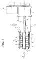
- the propeller pump 1 which is shown in FIG. 1 is a four-stage pump 2,3,4 and 5.
- This term stage refers to the succession on the shaft 6 of the pump 1 of two elements, namely on the one hand a propeller 7 which is fixed to the shaft 6 and which is therefore rotary, at the same time as this shaft 6 and on the other hand a rectifier 8 which is fixed on the external body 9 and cylindrical of the front part 10 of the pump 1.
- the propellers 7 comprise blades 11, arranged in a conventional manner according to the configuration illustrated in FIG. 2.
- the front part 10 of the pump which constitutes the active part thereof, opens into an elbow 12 for discharging the transported liquid.
- the shaft 6 is mounted cantilevered on a bearing 13 and is rotated by the motor 14.
- Figure 1 there is shown in the form of two arrows F the direction of circulation of the liquid conveyed by such a pump.
- the applicant has produced experimental equipment in which the body 9 supporting the rectifiers 8 as well as the outer casing 16 of the front part 10 of the pump 1 is made of a transparent material. This arrangement made it possible to visualize the formation of gas pockets, as a function of the gas concentrations of the charged liquid conveyed by the pump.
- the applicant has modified the conventional propeller pump shown in FIG. 1 using a gas withdrawal system.
- the peculiarity of this system is to come and sample the gas at the place where the stable pocket of gas is formed, that is to say on the upper surface of the blades of the propeller, at least on the one located at the first stage of the pump 1.
- the shaft 6 is hollow, it has an internal recess 18 which is connected, beyond the discharge elbow 12 and in a sealed manner, to a vacuum pump or to a ejector not shown.
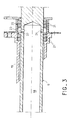
- FIG. 3 shows an embodiment of the sealed connection system between the recess of the shaft 6 and the device proper suction.
- the shaft 6 is surrounded by a stuffing box 19, delimiting on the one hand an internal housing 20 inside which are placed sealing braids 21 on either side of a chamber 22.
- This annular chamber 22 is connected by a connection orifice 23 to the vacuum pump or to the not shown ejector.
- the shaft 6, in line with the chamber 22, is pierced by several radial holes 24 which open into the central recess 18 of the shaft 6.
- each of the blades 11 of the propeller 7 is modified so as to be able to evacuate towards the internal recess 18 of the shaft 6 the gas pocket which forms on the upper surface 17 , 30 of said pale 11.
- the pale 11 is hollow and contains an interior chamber 26.
- This chamber 26 gives on the one hand on the interior recess 18 of the shaft 6 by means of pipes 27 and on the other hand gives on the extrados 17 of the pale 11 thanks to multiple perforations 28.
- the blade is hollowed out with a recess 29 made in the upper surface 17, as shown for the blade 11 'in FIG. 2.
- This recess 29 made along the leading edge 31 of the pale constitutes a recess 32 which delimits the hollow part 33 in the upper surface 17.
- This hollow part 33 in a way creates an open chamber formed in the upper surface.
- the gas pocket which forms on the upper surface is preferably housed along the recess 29 inside the hollow part 33.
- this hollow portion 33 makes it possible to decrease in relative value the volume occupied by the gas pocket; it is connected to the internal recess 18 of the axis 6 by a pipe 34. Thus it is possible to aspirate the gas pocket formed in this hollow part 33 using the gas withdrawal system fitted to the pump 1.
- FIGS. 4 and 5 The results obtained with respect to the operating characteristic of the pump 1 with different gas concentrations have been plotted on the curves of FIGS. 4 and 5 (figure shown opposite each of the curves).
- the pump 1 with which the tests in question were carried out was equipped on the first stage with a propeller, the blades of which are connected to the gas withdrawal system according to the first embodiment described above.
- FIG. 4 shows the results without using the suction system
- FIG. 5 shows the results with suction of the gas formed on the upper surface of the blades of the propeller of the first stage.
- the fibers suspended are hydrophilic fibers which, moreover, have the capacity to retain gas in a large proportion. This gas retention is obtained in particular during the dilution of the paper pulp, carried out in kneaders.
- the paper pulp is added to water and subjected to intense mechanical agitation during which a mixture of air and water is formed: a good part of this air is retained by the fibers in suspension.
- the second embodiment relates to a conventional centrifugal pump, the axial shaft of rotation of which is fitted, upstream of the rotor, with a propeller according to the invention, with discharge orifices connecting to the hollow shaft, the latter being itself connected to a gas withdrawal device, located for example in the pump body at the rear of the rotor.
- the invention is not limited to the embodiments which have been described above by way of non-exhaustive examples. Nor is it limited to the pumping of concentrated fibrous suspensions; it can also be applied for pumping other charged liquids containing a large amount of gas, for example emulsions in the food industry.
Landscapes
- Engineering & Computer Science (AREA)
- Mechanical Engineering (AREA)
- General Engineering & Computer Science (AREA)
- Structures Of Non-Positive Displacement Pumps (AREA)
Applications Claiming Priority (2)
| Application Number | Priority Date | Filing Date | Title |
|---|---|---|---|
| FR9214872 | 1992-12-04 | ||
| FR9214872A FR2698916B1 (fr) | 1992-12-04 | 1992-12-04 | Pompe perfectionnée notamment pour suspensions fibreuses concentrées. |
Publications (2)
| Publication Number | Publication Date |
|---|---|
| EP0600820A1 true EP0600820A1 (de) | 1994-06-08 |
| EP0600820B1 EP0600820B1 (de) | 1996-05-29 |
Family
ID=9436414
Family Applications (1)
| Application Number | Title | Priority Date | Filing Date |
|---|---|---|---|
| EP19930490022 Expired - Lifetime EP0600820B1 (de) | 1992-12-04 | 1993-11-25 | Pumpe, insbesondere für konzentrierte Fasersuspensionen |
Country Status (3)
| Country | Link |
|---|---|
| EP (1) | EP0600820B1 (de) |
| DE (1) | DE69302888T2 (de) |
| FR (1) | FR2698916B1 (de) |
Cited By (2)
| Publication number | Priority date | Publication date | Assignee | Title |
|---|---|---|---|---|
| WO1999054026A1 (en) * | 1998-04-22 | 1999-10-28 | Irish & Associates | A flow directing device for a medium consistency pump |
| US6210105B1 (en) | 1998-11-27 | 2001-04-03 | Irish & Asssociates | Flow directing device for a medium consistency pump |
Citations (9)
| Publication number | Priority date | Publication date | Assignee | Title |
|---|---|---|---|---|
| NL7401C (de) * | 1900-01-01 | |||
| US1423496A (en) * | 1920-11-11 | 1922-07-18 | Lewis H Haney | Pump |
| US3230890A (en) * | 1962-11-20 | 1966-01-25 | Yokota Hidekuni | Centrifugal pump |
| FR2223573A1 (en) * | 1973-02-16 | 1974-10-25 | Nalpas Claude | Hollow bladed screw propeller with internal passage - improves propulsive efficiency by reaction of expelled fluid |
| US3944406A (en) * | 1973-12-20 | 1976-03-16 | Veb Chemieanlagenbau-Und Montagekombinat | Centrifugal pump for pumping liquids with heavy gas content |
| FR2479870A1 (fr) * | 1980-04-07 | 1981-10-09 | Ahlstroem Oy | Dispositif et procede pour separer un gaz d'une suspension de fibres |
| EP0298693A2 (de) * | 1987-07-06 | 1989-01-11 | Kvaerner Pulping Technologies AB | Selbsteinspeisende Pumpe |
| EP0337394A2 (de) * | 1988-04-11 | 1989-10-18 | A. Ahlstrom Corporation | Wirkungsweise und Gerät zur Gasabtrennung von einem gepumpten Medium mittels einer Pumpe |
| EP0409456A2 (de) * | 1989-07-18 | 1991-01-23 | Kamyr Ab | Pumpe mit getrennter, an das Laufrad angrenzender Wirbelflügelwelle |
-
1992
- 1992-12-04 FR FR9214872A patent/FR2698916B1/fr not_active Expired - Fee Related
-
1993
- 1993-11-25 EP EP19930490022 patent/EP0600820B1/de not_active Expired - Lifetime
- 1993-11-25 DE DE1993602888 patent/DE69302888T2/de not_active Expired - Fee Related
Patent Citations (9)
| Publication number | Priority date | Publication date | Assignee | Title |
|---|---|---|---|---|
| NL7401C (de) * | 1900-01-01 | |||
| US1423496A (en) * | 1920-11-11 | 1922-07-18 | Lewis H Haney | Pump |
| US3230890A (en) * | 1962-11-20 | 1966-01-25 | Yokota Hidekuni | Centrifugal pump |
| FR2223573A1 (en) * | 1973-02-16 | 1974-10-25 | Nalpas Claude | Hollow bladed screw propeller with internal passage - improves propulsive efficiency by reaction of expelled fluid |
| US3944406A (en) * | 1973-12-20 | 1976-03-16 | Veb Chemieanlagenbau-Und Montagekombinat | Centrifugal pump for pumping liquids with heavy gas content |
| FR2479870A1 (fr) * | 1980-04-07 | 1981-10-09 | Ahlstroem Oy | Dispositif et procede pour separer un gaz d'une suspension de fibres |
| EP0298693A2 (de) * | 1987-07-06 | 1989-01-11 | Kvaerner Pulping Technologies AB | Selbsteinspeisende Pumpe |
| EP0337394A2 (de) * | 1988-04-11 | 1989-10-18 | A. Ahlstrom Corporation | Wirkungsweise und Gerät zur Gasabtrennung von einem gepumpten Medium mittels einer Pumpe |
| EP0409456A2 (de) * | 1989-07-18 | 1991-01-23 | Kamyr Ab | Pumpe mit getrennter, an das Laufrad angrenzender Wirbelflügelwelle |
Cited By (2)
| Publication number | Priority date | Publication date | Assignee | Title |
|---|---|---|---|---|
| WO1999054026A1 (en) * | 1998-04-22 | 1999-10-28 | Irish & Associates | A flow directing device for a medium consistency pump |
| US6210105B1 (en) | 1998-11-27 | 2001-04-03 | Irish & Asssociates | Flow directing device for a medium consistency pump |
Also Published As
| Publication number | Publication date |
|---|---|
| DE69302888D1 (de) | 1996-07-04 |
| DE69302888T2 (de) | 1996-11-07 |
| FR2698916A1 (fr) | 1994-06-10 |
| FR2698916B1 (fr) | 1995-03-03 |
| EP0600820B1 (de) | 1996-05-29 |
Similar Documents
| Publication | Publication Date | Title |
|---|---|---|
| EP0334737B1 (de) | Rotierende Strömungsmaschine, anwendbar als Pumpe, Verdichter, Propeller, Generator oder Arbeitsturbine | |
| FR2645184A1 (fr) | Appareil de fluidisation, de degazage et de pompage d'une suspension d'une matiere cellulosique fibreuse | |
| FR2549584A1 (de) | ||
| FR2582746A1 (fr) | Rotor de pompe, notamment rotor de pompe centrifuge | |
| FR3071283A1 (fr) | Pompe cardiaque equipee d'une turbine a pales internes | |
| FR2479870A1 (fr) | Dispositif et procede pour separer un gaz d'une suspension de fibres | |
| FR2471813A1 (fr) | Dispositif de traitement de fluide | |
| FR3065040A1 (fr) | Groupe de pompage et utilisation | |
| CA2258350A1 (fr) | Dispositif de compression de gaz humide comportant un etage de compression/separation integrees | |
| EP0600820B1 (de) | Pumpe, insbesondere für konzentrierte Fasersuspensionen | |
| EP3719283B1 (de) | Antriebsrad eines luft-öl-abscheiders eines anbaugerätegehäuses eines turbotriebwerks | |
| FR3095017A1 (fr) | Pivot de sortie pour pompe cardiaque à couplage magnétique. | |
| FR3095018A1 (fr) | Pompe cardiaque à couplage magnétique et à flux inverse. | |
| EP0736691B1 (de) | Innenzahnradpumpe mit radialen Zuführungsröhren | |
| FR2606094A1 (fr) | Pompe centrifuge en tant que pompe de circulation pour des installations de chauffage | |
| FR2765639A1 (fr) | Equipement d'inducteur pour pompe a grande capacite d'aspiration | |
| WO1987003051A1 (fr) | Compresseur de fluide gazeux, associe a un separateur gaz-liquide | |
| EP0600821A1 (de) | Betrieb einer mehrstufige Propellerpumpe für Fasersuspensionskonzentrate und insbesondere diesem Betrieb angepasste Propellerpumpe | |
| EP0058610B1 (de) | Verfahren und Einrichtung zum Erreichen eines Hochvakuums mit Gebrauch einer Einstufen-Flüssigkeitsringpumpe | |
| EP4387707B1 (de) | Intraventrikuläre herzpumpe mit verengtem kopf | |
| FR2663966A1 (fr) | Dispositif de triage d'un melange de pate a papier et de contaminants. | |
| FR2601084A1 (fr) | Pompe centrifuge pour le refoulement de fluides contenant des gaz | |
| FR3146923A3 (fr) | Nettoyeur de piscine à aspiration | |
| FR3124236A1 (fr) | Pompe à vide | |
| FR2653831A1 (fr) | Pompe volumetrique. |
Legal Events
| Date | Code | Title | Description |
|---|---|---|---|
| PUAI | Public reference made under article 153(3) epc to a published international application that has entered the european phase |
Free format text: ORIGINAL CODE: 0009012 |
|
| AK | Designated contracting states |
Kind code of ref document: A1 Designated state(s): BE CH DE LI |
|
| 17P | Request for examination filed |
Effective date: 19941125 |
|
| 17Q | First examination report despatched |
Effective date: 19951009 |
|
| GRAH | Despatch of communication of intention to grant a patent |
Free format text: ORIGINAL CODE: EPIDOS IGRA |
|
| GRAA | (expected) grant |
Free format text: ORIGINAL CODE: 0009210 |
|
| AK | Designated contracting states |
Kind code of ref document: B1 Designated state(s): BE CH DE LI |
|
| REG | Reference to a national code |
Ref country code: CH Ref legal event code: NV Representative=s name: BOVARD AG PATENTANWAELTE |
|
| REF | Corresponds to: |
Ref document number: 69302888 Country of ref document: DE Date of ref document: 19960704 |
|
| PLBE | No opposition filed within time limit |
Free format text: ORIGINAL CODE: 0009261 |
|
| STAA | Information on the status of an ep patent application or granted ep patent |
Free format text: STATUS: NO OPPOSITION FILED WITHIN TIME LIMIT |
|
| 26N | No opposition filed | ||
| PGFP | Annual fee paid to national office [announced via postgrant information from national office to epo] |
Ref country code: BE Payment date: 19981210 Year of fee payment: 6 |
|
| PG25 | Lapsed in a contracting state [announced via postgrant information from national office to epo] |
Ref country code: BE Free format text: LAPSE BECAUSE OF NON-PAYMENT OF DUE FEES Effective date: 19991130 |
|
| BERE | Be: lapsed |
Owner name: ETS F. MORET S.A. Effective date: 19991130 |
|
| PGFP | Annual fee paid to national office [announced via postgrant information from national office to epo] |
Ref country code: DE Payment date: 20051107 Year of fee payment: 13 |
|
| PGFP | Annual fee paid to national office [announced via postgrant information from national office to epo] |
Ref country code: CH Payment date: 20051111 Year of fee payment: 13 |
|
| PG25 | Lapsed in a contracting state [announced via postgrant information from national office to epo] |
Ref country code: LI Free format text: LAPSE BECAUSE OF NON-PAYMENT OF DUE FEES Effective date: 20061130 Ref country code: CH Free format text: LAPSE BECAUSE OF NON-PAYMENT OF DUE FEES Effective date: 20061130 |
|
| PG25 | Lapsed in a contracting state [announced via postgrant information from national office to epo] |
Ref country code: DE Free format text: LAPSE BECAUSE OF NON-PAYMENT OF DUE FEES Effective date: 20070601 |
|
| REG | Reference to a national code |
Ref country code: CH Ref legal event code: PL |