EP0409456A2 - Pumpe mit getrennter, an das Laufrad angrenzender Wirbelflügelwelle - Google Patents
Pumpe mit getrennter, an das Laufrad angrenzender Wirbelflügelwelle Download PDFInfo
- Publication number
- EP0409456A2 EP0409456A2 EP90307439A EP90307439A EP0409456A2 EP 0409456 A2 EP0409456 A2 EP 0409456A2 EP 90307439 A EP90307439 A EP 90307439A EP 90307439 A EP90307439 A EP 90307439A EP 0409456 A2 EP0409456 A2 EP 0409456A2
- Authority
- EP
- European Patent Office
- Prior art keywords
- impeller
- tube
- pump
- suspension
- consistency
- Prior art date
- Legal status (The legal status is an assumption and is not a legal conclusion. Google has not performed a legal analysis and makes no representation as to the accuracy of the status listed.)
- Granted
Links
- 239000000725 suspension Substances 0.000 claims abstract description 36
- 238000005086 pumping Methods 0.000 claims abstract description 27
- 229920001131 Pulp (paper) Polymers 0.000 claims abstract description 7
- 238000000034 method Methods 0.000 claims description 16
- 239000002657 fibrous material Substances 0.000 claims description 7
- 238000005243 fluidization Methods 0.000 claims description 4
- 239000007787 solid Substances 0.000 abstract description 6
- 238000009420 retrofitting Methods 0.000 description 3
- 238000007872 degassing Methods 0.000 description 2
- 238000009434 installation Methods 0.000 description 2
- 238000012986 modification Methods 0.000 description 2
- 230000004048 modification Effects 0.000 description 2
- 238000007689 inspection Methods 0.000 description 1
- 238000012856 packing Methods 0.000 description 1
Images
Classifications
-
- F—MECHANICAL ENGINEERING; LIGHTING; HEATING; WEAPONS; BLASTING
- F04—POSITIVE - DISPLACEMENT MACHINES FOR LIQUIDS; PUMPS FOR LIQUIDS OR ELASTIC FLUIDS
- F04D—NON-POSITIVE-DISPLACEMENT PUMPS
- F04D7/00—Pumps adapted for handling specific fluids, e.g. by selection of specific materials for pumps or pump parts
- F04D7/02—Pumps adapted for handling specific fluids, e.g. by selection of specific materials for pumps or pump parts of centrifugal type
- F04D7/04—Pumps adapted for handling specific fluids, e.g. by selection of specific materials for pumps or pump parts of centrifugal type the fluids being viscous or non-homogenous
- F04D7/045—Pumps adapted for handling specific fluids, e.g. by selection of specific materials for pumps or pump parts of centrifugal type the fluids being viscous or non-homogenous with means for comminuting, mixing stirring or otherwise treating
-
- B—PERFORMING OPERATIONS; TRANSPORTING
- B01—PHYSICAL OR CHEMICAL PROCESSES OR APPARATUS IN GENERAL
- B01F—MIXING, e.g. DISSOLVING, EMULSIFYING OR DISPERSING
- B01F27/00—Mixers with rotary stirring devices in fixed receptacles; Kneaders
- B01F27/60—Mixers with rotary stirring devices in fixed receptacles; Kneaders with stirrers rotating about a horizontal or inclined axis
- B01F27/71—Mixers with rotary stirring devices in fixed receptacles; Kneaders with stirrers rotating about a horizontal or inclined axis with propellers
- B01F27/711—Mixers with rotary stirring devices in fixed receptacles; Kneaders with stirrers rotating about a horizontal or inclined axis with propellers co-operating with stationary guiding means, e.g. baffles
-
- F—MECHANICAL ENGINEERING; LIGHTING; HEATING; WEAPONS; BLASTING
- F04—POSITIVE - DISPLACEMENT MACHINES FOR LIQUIDS; PUMPS FOR LIQUIDS OR ELASTIC FLUIDS
- F04D—NON-POSITIVE-DISPLACEMENT PUMPS
- F04D13/00—Pumping installations or systems
- F04D13/12—Combinations of two or more pumps
-
- F—MECHANICAL ENGINEERING; LIGHTING; HEATING; WEAPONS; BLASTING
- F05—INDEXING SCHEMES RELATING TO ENGINES OR PUMPS IN VARIOUS SUBCLASSES OF CLASSES F01-F04
- F05B—INDEXING SCHEME RELATING TO WIND, SPRING, WEIGHT, INERTIA OR LIKE MOTORS, TO MACHINES OR ENGINES FOR LIQUIDS COVERED BY SUBCLASSES F03B, F03D AND F03G
- F05B2210/00—Working fluid
- F05B2210/10—Kind or type
- F05B2210/13—Kind or type mixed, e.g. two-phase fluid
- F05B2210/132—Pumps with means for separating and evacuating the gaseous phase
Definitions
- a pumping system and method are provided that allow an ordinary paper pulp stock pump, designed for handling stock of about 3-8% consistency, to pump medium consistency pulp as well.
- the system according to the invention may be retrofit, although under some circumstances it is even desirable to provide a complete system according to the invention in new installations.
- the pumping system according to the invention does not in any way affect the mounting, speed of operation, or any other parameters of the ordinary stock pump, but merely provides additional elements that are not connected to, although they operatively interact with, the ordinary centrifugal stock pump, to allow it to pump medium consistency suspensions.
- a pumping system for suspensions which comprises the following elements: (a) A centrifugal pump having a housing containing an impeller, the impeller having a hub and blades. (b) Means for rotating the impeller about an impeller axis, in a first direction of rotation. (c) Means defining an inlet to the housing, and an outlet from the housing, for suspension being pumped. (d) A vaned tubular element having an open end. (e) Means for mounting the tubular element for rotation about an axis generally in line with the impeller axis, and so that the open end extends through the inlet so that it is positioned adjacent, but spaced from, the hub. And, (f) means for rotating the tube about its axis in a second direction of rotation, opposite the first direction.
- a pumping system specifically for pumping suspensions having a solids content of about 8-15%.
- the pumping system comprises: (a) A centrifugal pump having a housing containing an impeller, the impeller having a hub and blades. (b) Means for rotating the impeller about an impeller axis, in a first direction of rotation. (c) Means defining an inlet to the housing, and an outlet from the housing, for suspension being pumped. (d) A vaned tubular element having an open end.
- (e) Means for mounting the tubular element for rotation about an axis generally in line with the impeller axis, and so that the open end extends through the inlet so that it is positioned adjacent, but spaced from, the hub.
- (f) Means for rotating the tube about its axis at a velocity sufficient to fluidize the suspension of consistency about 8-15%.
- the means defining the inlet comprising a throat, the throat, tube, and vanes on the tube dimensioned so that there is a narrow clearance between the vanes and the throat to facilitate fluidization of the suspension by the tube.
- the means (e) and (f) comprise a shaft with a gas passage operatively communicating with the hollow interior of the tube, and (h) means are provided for withdrawing gas from the tube and gas passage.
- the means (h) may include a vacuum pump.
- the centrifugal pump consists essentially of the housing and impeller, being devoid of gas withdrawal means.
- the system is ideally mounted in a generally vertically disposed vessel for containing the suspension, the pump being disposed adjacent the bottom of the vessel and all of the elements of the pump system being mounted so that the impeller axis is generally horizontal.
- a method of the present invention it is possible to pump a suspension of cellulosic fibrous material (paper pulp) having a consistency of about 8-15% utilizing the apparatus earlier described.
- the method comprises the steps of: (a) Feeding the cellulosic fibrous material suspension at a consistency of about 8-15% toward the inlet to the pump housing. (b) Rotating the tube at a velocity sufficient to cause the suspension to be fluidized and to be forced toward the pump impeller. (c) Rotating the pump impeller to effect discharge of the suspension from the pump outlet. And, the further step (d) of withdrawing gas from adjacent the impeller.
- Step (d) preferably consists essentially of the step of causing gas to flow through the tube to be discharged at a position remote from the impeller, and steps (b) and (c) are practiced to cause the impeller to rotate in the direction opposite the direction of rotation of the tube.
- a method of retrofitting a centrifugal pumping system capable of handling cellulosic fibrous material suspension having a consistency of about 3-8%, so that it is capable of pumping a suspension having a consistency of up to about 15%.
- the method comprises the steps of: (a) Mounting a vaned hollow tube so that it extends through the inlet to the centrifugal pump, with an open end of the tube mounted adjacent, but spaced from, the hub of the impeller, and with the tube vanes having a small clearance between them and the inlet to the housing, and mounting the tube so that it is rotatable about an axis generally coincident with the impeller axis.
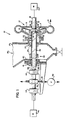
- a pumping system according to the present invention is shown generally by reference numeral 10 in FIGURE 1. While the system can be used with a variety of suspensions, it is eminently suited for use with comminuted cellulosic fibrous suspensions (paper pulp, or stock). It will be described in its preferred embodiment with respect to paper pulp pumping.
- the pump 12 is a standard centrifugal stock pump, which is designed for handling stock of a consistency of about 3-8%. It includes a housing 13 having an outlet 14 and an inlet 15, with a shaft 16 for rotating an impeller 17 about an axis (a generally horizontal axis in the embodiment illustrated in FIGURE 1).
- the impeller 17 includes a hub 18 and a plurality of blades 19, which can take a wide variety of forms and shapes, but preferably are solid and are illustrated only schematically in the drawings.
- the shaft 16 is rotated about its axis by the rotating means 20, which rotates the impeller 17 in the direction of arrow 21 (see FIGURE 2), at a speed that many vary widely, but typically is in the neighborhood of 600 rpm.
- the speed rotation is not sufficient to normally fluidize pulp having a consistency of about 8% or more.
- the housing 13 of the pump 12 is preferably mounted by an annular flange 22 to a like annular flange 23 of a generally vertically disposed vessel 25, which typically would be a storage vessel but also may be a treatment vessel. Pulp flows downwardly in the vessel 25 in the direction of arrow 26, and flows through a throat 27 into the inlet 15 for the pump 12.
- the element 30 comprises a hollow tubular body 32 having a plurality of vanes 33 thereon.
- the vanes may be in the form of ribs (right or helical), and may be continuous or -- as illustrated in the drawings -- discrete.
- the tube 32 and the vanes 33 are dimensioned with respect to the throat 27 so that there is only a small clearance between the vanes and the throat 27 and inlet 15.
- the clearance 35 may be no more than a few centimeters, but the exact clearance will depend upon the particular conditions.
- the purpose of the small clearance 35 is to assist the tube 30 -- when rotated as described subsequently -- to fluidize the pulp as it moves downwardly in vessel 25 toward inlet 15.
- the tube 30 has an open end 37.
- the tube 32 is mounted, by the shaft 39, bearings 41 and flange 42, and bearings 44, for rotation about an axis that is essentially coincident with the impeller axis, and so that the end 37 is adjacent, but slightly (e.g. a few centimeters) spaced from the hub 18 of the pump 12.
- the spacing between the open end 37 of the tube 32 and the hub 18 is such that little or no suspension will enter the hollow tube 32 during normal operating conditions, but any gas which may collect at the axis of the impeller (as typically occurs when pumping medium consistency suspensions) may pass into the hollow interior of the tube 32.
- the system 10 also includes means -- such as motor 46 -- for rotating the tube 30 (via shaft 39) at a speed sufficient to fluidize pulp having a consistency of about 8-15%.
- Speed of rotation typically is greater than 800 rpm (typically greater than the speed of rotation of impeller 17), although it may vary widely.
- the rotation of the vaned tube 30 causes the pulp to be fluidized, and forces the pulp toward the impeller 17, so that it is immediately acted upon the blades 19 while it is in the fluidized condition.
- Means are also preferably provided for the removal of gas, which collects at the impeller axis and has a tendency to move into the tube 32.
- a passage 48 is provided in the shaft 39.
- the passage 48 continues to the stationary housing 50, which surrounds the shaft 39, and at the housing 50 one or more radially extending passages are provided communicating with the axial passage 48 in the shaft 39, to allow the gas to move radially outwardly into one or more gas discharge conduits 51.
- the normal rotation of the shaft 39 and tube 30 will have a tendency to draw gas from the tube 32 to be discharged through the pipes 51, however where desired some short blade elements which extend radially may be provided on the shaft 39 within the housing 50 to facilitate gas movement, and if desired the tube 51 may be hooked up to an optional exterior vacuum pump 52.
- a normal stock pump 12 is capable of pumping pulp suspensions having a consistency of about 8-15%, the speeds of rotation of the vaned tube 30 and the impeller 17 being set independently and to the desired levels depending upon the particular conditions encountered (although usually the rotational speed of element 30 is greater than that of element 17).
- the system 10 it is possible to practice a method of pumping a suspension of cellulosic fibrous material having a consistency of about 8-15%.
- the method comprises the steps of feeding the cellulosic fibrous material suspension at a consistency of about 8-15% toward the inlet 15 to the pump housing 13; rotating the element 30 at a velocity sufficient to cause the suspension in the area of throat 27 to be fluidized, and to be forced toward the pump impeller 17; and rotating the pump impeller 17, utilizing motor 20, to effect discharge of the suspension from the pulp outlet 14.
- the gas withdrawal step consisting essentially of causing the gas to flow through the hollow tube 32, and gas passageway 48, to be discharged through conduit 51 at a position remote from the impeller 17.
- the speeds of rotation of the elements 32, 17 are independently controlled, and preferably they are in opposite directions (21, 47 -- see FIGURE 2).
- the invention also contemplates a method of retrofitting a conventional pumping system which is capable of handling stock having a consistency of about 3-8%, so that it is capable of pumping medium consistency stock.
- Pre-existing components of a conventional stock pump would consist of all of the elements illustrated in FIGURE 1 except for the vaned tube 30 and the elements associated therewith. Retrofitting is easily accomplished merely by forming an opening in the vessel 25 opposite the inlet 15, and utilizing flange 42 and packing 41 -- and with accessory support structures for bearings 44 mounted on the flange 53 and outstanding arm 54, for cooperation with the flange 42, the structure is easily mounted in place.
- the vaned tube 30 is positioned so that the open end 37 thereof is adjacent but spaced from the hub 18, and the tube 32 and vanes 33 are dimensioned so that the clearance 35 between the vanes 33 and the throat 27 is small enough to facilitate fluidization of the pulp by the rotating vaned tube 30.
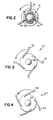
- FIGURES 3 and 4 illustrate two alternative embodiments of pumping systems according to the invention, which systems differ from that of FIGURES 1 and 2 essentially only in the configuration of the impellers. While the impeller of the FIGURE 2 embodiment is very practical for fluidizing the pulp, it is less efficient for pumping.
- the FIGURES 3 and 4 embodiment impellers are about twice as efficient, or more, as the FIGURE 2 embodiment as far as actual pulp pumping efficiency is concerned.
- structures comparable to those in the FIG. 2 embodiment are shown by the same two digit reference numeral, only preceded by a "1" in the case of the FIG. 3 embodiment, and preceded by a "2" in the case of the FIG. 4 embodiment.
- the impeller 117 has a hub 188 and solid blades 119 which curve slightly convexly at the ends thereof, as illustrated in FIG. 3.
- the impeller 217 has a hub 218 and solid blades 219 which have a concave outer periphery.
Landscapes
- Engineering & Computer Science (AREA)
- Mechanical Engineering (AREA)
- General Engineering & Computer Science (AREA)
- Chemical & Material Sciences (AREA)
- Chemical Kinetics & Catalysis (AREA)
- Paper (AREA)
- Structures Of Non-Positive Displacement Pumps (AREA)
- Vehicle Body Suspensions (AREA)
- Reciprocating Pumps (AREA)
- Saccharide Compounds (AREA)
- Medicines Containing Plant Substances (AREA)
- Extraction Or Liquid Replacement (AREA)
- Medicines Containing Material From Animals Or Micro-Organisms (AREA)
- Polysaccharides And Polysaccharide Derivatives (AREA)
Priority Applications (1)
| Application Number | Priority Date | Filing Date | Title |
|---|---|---|---|
| AT90307439T ATE104020T1 (de) | 1989-07-18 | 1990-07-06 | Pumpe mit getrennter, an das laufrad angrenzender wirbelfluegelwelle. |
Applications Claiming Priority (2)
| Application Number | Priority Date | Filing Date | Title |
|---|---|---|---|
| US381067 | 1989-07-18 | ||
| US07/381,067 US4976586A (en) | 1989-07-18 | 1989-07-18 | Pump with separate fluidizing vaned shaft adjacent impeller |
Publications (3)
| Publication Number | Publication Date |
|---|---|
| EP0409456A2 true EP0409456A2 (de) | 1991-01-23 |
| EP0409456A3 EP0409456A3 (en) | 1991-07-17 |
| EP0409456B1 EP0409456B1 (de) | 1994-04-06 |
Family
ID=23503529
Family Applications (1)
| Application Number | Title | Priority Date | Filing Date |
|---|---|---|---|
| EP90307439A Expired - Lifetime EP0409456B1 (de) | 1989-07-18 | 1990-07-06 | Pumpe mit getrennter, an das Laufrad angrenzender Wirbelflügelwelle |
Country Status (10)
| Country | Link |
|---|---|
| US (1) | US4976586A (de) |
| EP (1) | EP0409456B1 (de) |
| JP (1) | JPH0351386A (de) |
| AT (1) | ATE104020T1 (de) |
| BR (1) | BR9003452A (de) |
| CA (1) | CA1333457C (de) |
| DE (1) | DE69007888T2 (de) |
| FI (1) | FI102632B (de) |
| NO (1) | NO175500C (de) |
| SE (1) | SE9001781L (de) |
Cited By (5)
| Publication number | Priority date | Publication date | Assignee | Title |
|---|---|---|---|---|
| EP0600821A1 (de) * | 1992-12-04 | 1994-06-08 | Etablissements F. Moret (S.A.) | Betrieb einer mehrstufige Propellerpumpe für Fasersuspensionskonzentrate und insbesondere diesem Betrieb angepasste Propellerpumpe |
| EP0600820A1 (de) * | 1992-12-04 | 1994-06-08 | Etablissements F. Moret (S.A.) | Pumpe, insbesondere für konzentrierte Fasersuspensionen |
| WO1996032591A3 (en) * | 1995-04-12 | 1996-12-12 | Grudinin Alexandr Vladimirovic | Pump for conveying a moist pulp |
| WO1999054026A1 (en) * | 1998-04-22 | 1999-10-28 | Irish & Associates | A flow directing device for a medium consistency pump |
| US6210105B1 (en) | 1998-11-27 | 2001-04-03 | Irish & Asssociates | Flow directing device for a medium consistency pump |
Families Citing this family (7)
| Publication number | Priority date | Publication date | Assignee | Title |
|---|---|---|---|---|
| SE9201477L (sv) * | 1992-05-11 | 1993-06-28 | Kamyr Ab | Saett vid blekning av massa utan anvaendning av klorkemikalier |
| FI97332C (fi) * | 1993-12-23 | 2006-11-24 | Pom Tech Oy Ab | Kaasunerotuspumppu paperinvalmistuksessa virtaavan veden tai nestemäisen kuitususpension ja ilman erottamiseksi toisistaan pumppauksen yhteydessä |
| US5847922A (en) * | 1996-07-29 | 1998-12-08 | Compaq Computer Corporation | Portable computer docking station having improved speaker apparatus therein |
| US7419354B2 (en) * | 2004-04-05 | 2008-09-02 | Konstandinos Zamfes | Centrifugal pump with screw pump accelerator |
| US7267529B2 (en) | 2004-12-08 | 2007-09-11 | Taylor John A | Deaeration system |
| USD681704S1 (en) * | 2011-05-28 | 2013-05-07 | Peio Todorov Stoyanov | Decorative liquid metal degassing impeller |
| CN102506440A (zh) * | 2011-10-20 | 2012-06-20 | 安徽理工大学 | 一种嵌入式干法磁选净化、回粉磁选再磨工艺 |
Family Cites Families (10)
| Publication number | Priority date | Publication date | Assignee | Title |
|---|---|---|---|---|
| DE517377C (de) * | 1931-02-13 | Hermann Hoppe | Pumpe fuer breiiges oder Stuecke enthaltendes Foerdergut mit Zubringevorrichtung | |
| DE1403859A1 (de) * | 1960-09-06 | 1968-10-31 | Neidl Dipl Ing Georg | Umlaufpumpe |
| SE389351B (sv) * | 1975-03-14 | 1976-11-01 | Kamyr Ab | Sett och anordning for fordelning och inblandning av gas och/eller vetska i massasuspensioner av hog koncentration. |
| US4435193A (en) * | 1980-04-07 | 1984-03-06 | Kamyr Ab | Controlling operation of a centrifugal pump |
| SU926372A1 (ru) * | 1980-06-02 | 1982-05-07 | Предприятие П/Я М-5356 | Центробежный насос |
| SE435951B (sv) * | 1983-03-14 | 1984-10-29 | Sunds Defibrator | Centrifugalpump med skruvmatare for pumpning av massa med hog koncentration |
| US4637779A (en) * | 1985-05-17 | 1987-01-20 | Kamyr, Inc. | Two stage medium consistency pulp pumping |
| US4770604A (en) * | 1986-10-06 | 1988-09-13 | Ingersoll-Rand Company | Pulp centrifugal pump |
| US4884943A (en) * | 1987-06-25 | 1989-12-05 | A. Ahlstrom Corporation | Method and apparatus for pumping high-consistency fiber suspension |
| US4826398A (en) * | 1987-07-06 | 1989-05-02 | Kamyr Ab | Medium consistency pump with self-feeding |
-
1989
- 1989-07-18 US US07/381,067 patent/US4976586A/en not_active Expired - Lifetime
- 1989-09-28 CA CA000613870A patent/CA1333457C/en not_active Expired - Fee Related
-
1990
- 1990-05-17 SE SE9001781A patent/SE9001781L/ not_active Application Discontinuation
- 1990-06-15 FI FI903019A patent/FI102632B/fi active IP Right Grant
- 1990-07-04 JP JP2177211A patent/JPH0351386A/ja active Pending
- 1990-07-06 AT AT90307439T patent/ATE104020T1/de not_active IP Right Cessation
- 1990-07-06 DE DE69007888T patent/DE69007888T2/de not_active Expired - Fee Related
- 1990-07-06 EP EP90307439A patent/EP0409456B1/de not_active Expired - Lifetime
- 1990-07-17 NO NO903184A patent/NO175500C/no unknown
- 1990-07-17 BR BR909003452A patent/BR9003452A/pt not_active Application Discontinuation
Cited By (7)
| Publication number | Priority date | Publication date | Assignee | Title |
|---|---|---|---|---|
| EP0600821A1 (de) * | 1992-12-04 | 1994-06-08 | Etablissements F. Moret (S.A.) | Betrieb einer mehrstufige Propellerpumpe für Fasersuspensionskonzentrate und insbesondere diesem Betrieb angepasste Propellerpumpe |
| EP0600820A1 (de) * | 1992-12-04 | 1994-06-08 | Etablissements F. Moret (S.A.) | Pumpe, insbesondere für konzentrierte Fasersuspensionen |
| FR2698916A1 (fr) * | 1992-12-04 | 1994-06-10 | Moret Ets F | Pompe perfectionnée notamment pour suspensions fibreuses concentrées. |
| FR2698918A1 (fr) * | 1992-12-04 | 1994-06-10 | Moret Ets F | Utilisation d'une pompe hélice multiétage pour le pompage de suspensions fibreuses concentrées et pompe hélice spécialement adaptée pour cette utilisation. |
| WO1996032591A3 (en) * | 1995-04-12 | 1996-12-12 | Grudinin Alexandr Vladimirovic | Pump for conveying a moist pulp |
| WO1999054026A1 (en) * | 1998-04-22 | 1999-10-28 | Irish & Associates | A flow directing device for a medium consistency pump |
| US6210105B1 (en) | 1998-11-27 | 2001-04-03 | Irish & Asssociates | Flow directing device for a medium consistency pump |
Also Published As
| Publication number | Publication date |
|---|---|
| DE69007888T2 (de) | 1994-10-13 |
| NO903184D0 (no) | 1990-07-17 |
| SE9001781D0 (sv) | 1990-05-17 |
| NO175500C (no) | 1994-10-19 |
| JPH0351386A (ja) | 1991-03-05 |
| ATE104020T1 (de) | 1994-04-15 |
| EP0409456B1 (de) | 1994-04-06 |
| EP0409456A3 (en) | 1991-07-17 |
| BR9003452A (pt) | 1991-08-27 |
| CA1333457C (en) | 1994-12-13 |
| DE69007888D1 (de) | 1994-05-11 |
| US4976586A (en) | 1990-12-11 |
| FI102632B1 (fi) | 1999-01-15 |
| FI102632B (fi) | 1999-01-15 |
| NO175500B (no) | 1994-07-11 |
| FI903019A0 (fi) | 1990-06-15 |
| SE9001781L (sv) | 1991-01-19 |
| NO903184L (no) | 1991-01-21 |
Similar Documents
| Publication | Publication Date | Title |
|---|---|---|
| CA1315600C (en) | Medium consistency pump with self-feeding | |
| US4776758A (en) | Combined fluidizing and vacuum pump | |
| US4637779A (en) | Two stage medium consistency pulp pumping | |
| US4921400A (en) | Pump and a method of separating gas by such from a fluid to be pumped | |
| US4976586A (en) | Pump with separate fluidizing vaned shaft adjacent impeller | |
| CA1316397C (en) | Centrifugal pump | |
| US3454163A (en) | Method of separating solids from liquids | |
| US6827820B1 (en) | Degassing centrifugal apparatus, process for pumping and degassing a fluid and process for producing paper or board | |
| US5019136A (en) | Method and apparatus for separating gas with a pump from a medium being pumped | |
| US4981413A (en) | Pump for and method of separating gas from a fluid to be pumped | |
| US4410337A (en) | Method and an apparatus for separating a gas from a fibre suspension | |
| EP0478228B1 (de) | Verfahren und Apparat zur Freisetzung von Gas aus einem Flüssigkeit/Feststoff-Gemisch | |
| NL8300458A (nl) | Verbeterde gasverstoppingen werende inrichting. | |
| US4744722A (en) | Method and apparatus for the mixing of liquid or gas into pulp stock | |
| US5087171A (en) | Paper pulp centrifugal pump with gas separation | |
| US5605442A (en) | Centrifugal pump for pumping fiber suspensions | |
| EP0347088B1 (de) | Arbeitsweise und Gerät zum Verpumpen eines hochkonsistenten Mediums | |
| US6210105B1 (en) | Flow directing device for a medium consistency pump | |
| US6464758B1 (en) | Apparatus and method for degassing a liquid or pasty medium in a machine for producing and/or upgrading a fiber material web | |
| GB2192230A (en) | A centrifugal pump for conveying gas-containing media | |
| WO1999054026A1 (en) | A flow directing device for a medium consistency pump | |
| WO1998021480A1 (en) | Centrifugal pump | |
| JPH10509483A (ja) | ガスと共にパルプを処理するガス抜き排出部材を備えた反応装置 |
Legal Events
| Date | Code | Title | Description |
|---|---|---|---|
| PUAI | Public reference made under article 153(3) epc to a published international application that has entered the european phase |
Free format text: ORIGINAL CODE: 0009012 |
|
| AK | Designated contracting states |
Kind code of ref document: A2 Designated state(s): AT BE CH DE DK ES FR GB GR IT LI LU NL SE |
|
| RBV | Designated contracting states (corrected) |
Designated state(s): AT DE FR |
|
| PUAL | Search report despatched |
Free format text: ORIGINAL CODE: 0009013 |
|
| AK | Designated contracting states |
Kind code of ref document: A3 Designated state(s): AT BE CH DE DK ES FR GB GR IT LI LU NL SE |
|
| 17P | Request for examination filed |
Effective date: 19920116 |
|
| 17Q | First examination report despatched |
Effective date: 19930210 |
|
| GRAA | (expected) grant |
Free format text: ORIGINAL CODE: 0009210 |
|
| AK | Designated contracting states |
Kind code of ref document: B1 Designated state(s): AT DE FR |
|
| REF | Corresponds to: |
Ref document number: 104020 Country of ref document: AT Date of ref document: 19940415 Kind code of ref document: T |
|
| REF | Corresponds to: |
Ref document number: 69007888 Country of ref document: DE Date of ref document: 19940511 |
|
| ET | Fr: translation filed | ||
| PG25 | Lapsed in a contracting state [announced via postgrant information from national office to epo] |
Ref country code: AT Effective date: 19940706 |
|
| PLBE | No opposition filed within time limit |
Free format text: ORIGINAL CODE: 0009261 |
|
| STAA | Information on the status of an ep patent application or granted ep patent |
Free format text: STATUS: NO OPPOSITION FILED WITHIN TIME LIMIT |
|
| 26N | No opposition filed | ||
| PG25 | Lapsed in a contracting state [announced via postgrant information from national office to epo] |
Ref country code: FR Effective date: 19950331 |
|
| PG25 | Lapsed in a contracting state [announced via postgrant information from national office to epo] |
Ref country code: DE Effective date: 19950401 |
|
| REG | Reference to a national code |
Ref country code: FR Ref legal event code: ST |