EP0601228A1 - Entraînement à moteur électrique - Google Patents
Entraînement à moteur électrique Download PDFInfo
- Publication number
- EP0601228A1 EP0601228A1 EP92120906A EP92120906A EP0601228A1 EP 0601228 A1 EP0601228 A1 EP 0601228A1 EP 92120906 A EP92120906 A EP 92120906A EP 92120906 A EP92120906 A EP 92120906A EP 0601228 A1 EP0601228 A1 EP 0601228A1
- Authority
- EP
- European Patent Office
- Prior art keywords
- magnetic body
- electric motor
- motor drive
- feature
- drive according
- Prior art date
- Legal status (The legal status is an assumption and is not a legal conclusion. Google has not performed a legal analysis and makes no representation as to the accuracy of the status listed.)
- Granted
Links
- 239000002184 metal Substances 0.000 claims description 12
- 238000011144 upstream manufacturing Methods 0.000 claims description 4
- 229910001369 Brass Inorganic materials 0.000 claims description 2
- 239000010951 brass Substances 0.000 claims description 2
- 229910000859 α-Fe Inorganic materials 0.000 claims description 2
- 230000006835 compression Effects 0.000 claims 1
- 238000007906 compression Methods 0.000 claims 1
- 230000000284 resting effect Effects 0.000 claims 1
- 239000000523 sample Substances 0.000 description 5
- 125000006850 spacer group Chemical group 0.000 description 4
- 238000001514 detection method Methods 0.000 description 3
- 230000001070 adhesive effect Effects 0.000 description 2
- OKTJSMMVPCPJKN-UHFFFAOYSA-N Carbon Chemical compound [C] OKTJSMMVPCPJKN-UHFFFAOYSA-N 0.000 description 1
- 239000000853 adhesive Substances 0.000 description 1
- 238000004026 adhesive bonding Methods 0.000 description 1
- 229910052799 carbon Inorganic materials 0.000 description 1
- 230000001419 dependent effect Effects 0.000 description 1
- 230000005284 excitation Effects 0.000 description 1
- 238000002347 injection Methods 0.000 description 1
- 239000007924 injection Substances 0.000 description 1
- 238000009434 installation Methods 0.000 description 1
- 239000006249 magnetic particle Substances 0.000 description 1
- 238000004519 manufacturing process Methods 0.000 description 1
- 238000004804 winding Methods 0.000 description 1
Images


Classifications
-
- G—PHYSICS
- G01—MEASURING; TESTING
- G01P—MEASURING LINEAR OR ANGULAR SPEED, ACCELERATION, DECELERATION, OR SHOCK; INDICATING PRESENCE, ABSENCE, OR DIRECTION, OF MOVEMENT
- G01P3/00—Measuring linear or angular speed; Measuring differences of linear or angular speeds
- G01P3/42—Devices characterised by the use of electric or magnetic means
- G01P3/44—Devices characterised by the use of electric or magnetic means for measuring angular speed
- G01P3/48—Devices characterised by the use of electric or magnetic means for measuring angular speed by measuring frequency of generated current or voltage
- G01P3/481—Devices characterised by the use of electric or magnetic means for measuring angular speed by measuring frequency of generated current or voltage of pulse signals
- G01P3/487—Devices characterised by the use of electric or magnetic means for measuring angular speed by measuring frequency of generated current or voltage of pulse signals delivered by rotating magnets
-
- H—ELECTRICITY
- H02—GENERATION; CONVERSION OR DISTRIBUTION OF ELECTRIC POWER
- H02K—DYNAMO-ELECTRIC MACHINES
- H02K1/00—Details of the magnetic circuit
- H02K1/06—Details of the magnetic circuit characterised by the shape, form or construction
- H02K1/22—Rotating parts of the magnetic circuit
- H02K1/27—Rotor cores with permanent magnets
- H02K1/2706—Inner rotors
- H02K1/272—Inner rotors the magnetisation axis of the magnets being perpendicular to the rotor axis
- H02K1/2726—Inner rotors the magnetisation axis of the magnets being perpendicular to the rotor axis the rotor consisting of a single magnet or two or more axially juxtaposed single magnets
- H02K1/2733—Annular magnets
-
- H—ELECTRICITY
- H02—GENERATION; CONVERSION OR DISTRIBUTION OF ELECTRIC POWER
- H02K—DYNAMO-ELECTRIC MACHINES
- H02K23/00—DC commutator motors or generators having mechanical commutator; Universal AC/DC commutator motors
- H02K23/66—Structural association with auxiliary electric devices influencing the characteristic of, or controlling, the machine, e.g. with impedances or switches
Definitions
- the invention relates to an electric motor drive according to claim 1;
- Such drives are particularly suitable as an auxiliary drive in a motor vehicle with a magnet wheel attached to the rotor shaft as a magnetic body for generating a speed-proportional signal in a stator-side Hall probe device, e.g. for use with speed-controlled or direction-controlled window drives.
- a commutator motor is known from EP-A1-0 489 940, in which Hall probes are arranged for speed control on a stator-side electronic connection plate, to which a magnet wheel attached directly to the rotor shaft is assigned.
- the attachment of the magnet wheel to the rotor shaft can e.g. by an appropriate press fit and / or adhesive property.
- an electromotive drive in particular for a motor vehicle, with a commutator and a magnetic pole wheel arranged on the rotor shaft for speed and / or direction of rotation detection and interacting with a stator-side Hall sensor
- a spacer bush is first placed on the rotor shaft in a rotationally fixed manner and then the magnet wheel is either pressed or plugged or glued onto the outer circumference concentrically with the spacer bush, or is fastened with a positive fit; for form-fitting fastening, the spacer sleeve is provided on the outer circumference with a flattened portion on the one hand and the magnet wheel on the corresponding inside with a corresponding flattened portion on the other.
- the spacer sleeve lies with one End face on the commutator and is fixed on its other end face with the aid of a locking ring which can be inserted in a form-fitting manner in the rotor shaft.
- the magnetic pole wheel can consist of a plastic body with plastic-bound magnetic particles or of a non-magnetic base body in which permanent magnets are inserted.
- the invention has for its object to be able to ensure a secure fixation of the relatively brittle magnetic body on the rotor shaft with simple means in a small installation size with simple means.
- This object is achieved by an electromotive drive designed according to the teaching of claim 1; advantageous embodiments of the invention are the subject of the dependent claims.
- the electromotive drive it is possible, regardless of the brittleness of the magnetic body, to fix it axially and tangentially to the rotor shaft by means of the holding part, which can be stably designed with regard to an adequate press fit, and to fix the magnetic body relative to the rotor shaft on the rotor shaft due to its sliding seat holder to be centered independently of the holding part, the axial front or rear mounting of the holding body relative to the magnetic body making it possible to radially not enlarge the size and axially compact fastening possibility for the magnetic body.
- the magnetic body and the holding part are combined to form a preassembled component unit, such that the component unit only has to be plugged onto the rotor shaft in one handling step.
- FIG. 1 shows an axial partial sectional view of a commutator motor with permanent magnets 11, 12 provided for excitation on the inner circumferential surface of a motor housing 1 and a rotor package 21 fastened to a rotor shaft 2, provided with a rotor winding, and an axially upstream commutator 22 which is connected to a brush support plate 13 held carbon brushes is ground.
- the rotor shaft 2 e.g. by gluing, a magnet wheel NS with an appropriately polarized permanent magnet body 3 made of a plastic-bonded ferrite magnetic ring, to which 14 Hall probes 9, 10 are assigned on a stator-side circuit board.
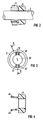
- 2-4 show a first embodiment of a fixation of the permanent magnet body 3 according to the invention on a rotor shaft 2.
- a plastic bushing 4 which is axially projecting, is pressed onto the right front side of the magnetic body 3, which is only plugged into the sliding seat and thus self-centering on the rotor shaft 2
- Snap hooks 41, 42 are inserted through grooves 31, 32 of the magnetic body 3 and locked in contact with the left end face of the magnetic body 3.
- the plastic bushing 4 with the snap hooks 41, 42 is advantageously designed as a one-piece plastic injection molded part.
- the holding part 5, 6 consists of a heat-resistant metal disk 5, in particular a brass disk, which is located directly or indirectly against an end face of the magnetic body 3, and a spring bracket 6 arranged in front thereof and having axially projecting grooves 31. 32 of the magnetic body 3 reaching and on the other end face of the magnetic body 3 supporting arms 61,62; in the latter case, the magnetic body 3 is in turn only applied in a centering sliding fit and the metal disk 5 in a press fit on the rotor shaft 2.
- the spring clip 6, which is preferably fitted onto the rotor shaft 2 without a press fit, is in a form-locking rotational drive with the metal disk 5 fixed on the rotor shaft 2 via axially projecting drive arms 63, 64; for this purpose, the metal disk 5 according to FIG. 9 has flats 53, 54 corresponding to the flat driving arms 63, 64 on the outer circumference of the metal disk 5. Between the abovementioned flats 53, 54 there are similar flats 51, 52, against which the likewise flat holding arms 61, 62, which overlap the magnetic body 3, rest.
- the spring clip 6 furthermore has axially projecting spring tabs 65 distributed over its circumference, with which the spring clip 6 can be supported resiliently on the opposite end face of the metal disk 5.
- the holding part 7, 8 consists of one holding bracket 7 or 8, which lies or lies on each of the two end faces of the magnetic body 3, through a bracket, preferably also in a groove 31 of the magnetic body 3 engaging, connecting web 71 are interconnected.
- the free ends of the holding brackets 7 and 8 opposite the connecting web 71 are provided with axial driving webs 72, 82, which also expediently engage in a corresponding groove 32 of the magnetic body 3.
- the two end-side annular holding parts 7, 8 with their rotor shaft openings 73, 83, which are dimensioned in the sense of a press fit holder on the rotor shaft 2, can either be pre-bent as shown in FIG. 12 and then slipped radially over the magnetic body 3 with the free ends springing up, or as shown in FIG. 13 after advantageous manufacture be bent as a flat bending-stamping part over the magnetic body 3.
- the permanent magnet body 3 and the holding part 7, 8 are thus combined in a simple manner to form a preassembled component unit which can be plugged onto the rotor shaft 2 in only one assembly handling operation, the permanent magnet body 3 with its correspondingly provided rotor shaft opening 33 centered in the sliding fit on the rotor shaft 2 itself and is pushed onto the rotor shaft in a press fit by the holding part 7, 8 with the rotor shaft opening 73 or 83 correspondingly undersized with respect to the rotor shaft opening 33.
- the permanent magnet body 3 and the plastic bushing 4 with the molded-on snap hooks 41, 42 and the metal disk 5 with the the spring bracket 6, which rests in a form-fitting manner is combined with the permanent magnet body 3 as preassembled component units and is then applied in one piece to the rotor shaft 2.
Landscapes
- Engineering & Computer Science (AREA)
- Power Engineering (AREA)
- Physics & Mathematics (AREA)
- General Physics & Mathematics (AREA)
- Permanent Field Magnets Of Synchronous Machinery (AREA)
- Connection Of Motors, Electrical Generators, Mechanical Devices, And The Like (AREA)
Priority Applications (4)
| Application Number | Priority Date | Filing Date | Title |
|---|---|---|---|
| EP92120906A EP0601228B1 (fr) | 1992-12-08 | 1992-12-08 | Entraînement à moteur électrique |
| ES92120906T ES2061308T3 (es) | 1992-12-08 | 1992-12-08 | Accionamiento por motor electrico. |
| DE59200663T DE59200663D1 (de) | 1992-12-08 | 1992-12-08 | Elektromotorischer Antrieb. |
| US08/163,229 US5565721A (en) | 1992-12-08 | 1993-12-07 | Electromotive drive |
Applications Claiming Priority (1)
| Application Number | Priority Date | Filing Date | Title |
|---|---|---|---|
| EP92120906A EP0601228B1 (fr) | 1992-12-08 | 1992-12-08 | Entraînement à moteur électrique |
Publications (2)
| Publication Number | Publication Date |
|---|---|
| EP0601228A1 true EP0601228A1 (fr) | 1994-06-15 |
| EP0601228B1 EP0601228B1 (fr) | 1994-10-19 |
Family
ID=8210288
Family Applications (1)
| Application Number | Title | Priority Date | Filing Date |
|---|---|---|---|
| EP92120906A Expired - Lifetime EP0601228B1 (fr) | 1992-12-08 | 1992-12-08 | Entraînement à moteur électrique |
Country Status (4)
| Country | Link |
|---|---|
| US (1) | US5565721A (fr) |
| EP (1) | EP0601228B1 (fr) |
| DE (1) | DE59200663D1 (fr) |
| ES (1) | ES2061308T3 (fr) |
Cited By (5)
| Publication number | Priority date | Publication date | Assignee | Title |
|---|---|---|---|---|
| WO2000022442A1 (fr) * | 1998-10-12 | 2000-04-20 | Robert Bosch Gmbh | Roue polaire constituee d'un corps magnetique creux et d'un element de retenue |
| WO2000022718A1 (fr) * | 1998-10-09 | 2000-04-20 | Robert Bosch Gmbh | Moteur electrique |
| FR2925786A1 (fr) * | 2007-12-19 | 2009-06-26 | Valeo Equip Electr Moteur | Agencement d'un porte-cible sur un ventilateur de machine electrique tournante |
| DE102009039082A1 (de) * | 2009-08-27 | 2011-03-03 | Valeo Schalter Und Sensoren Gmbh | Magnetbaugruppe für eine Drehmoment- und/oder Drehwinkelsensoranordnung mit einem Magnetring und Herstellungsverfahren |
| EP2141785A3 (fr) * | 2008-07-04 | 2016-06-01 | Mabuchi Motor Co., Ltd. | Support magnétique de capteur, moteur doté du support incorporé dans celui-ci, et procédé de fabrication du moteur |
Families Citing this family (34)
| Publication number | Priority date | Publication date | Assignee | Title |
|---|---|---|---|---|
| DE19546595A1 (de) | 1995-12-13 | 1997-06-19 | Siemens Ag | Drehzahl- und/oder Drehrichtung-Sensorvorrichtung |
| EP0902880B1 (fr) * | 1996-06-05 | 2002-10-23 | Valeo Auto-Electric Wischer und Motoren GmbH | Tore magnetique |
| US5786646A (en) * | 1996-10-01 | 1998-07-28 | Emerson Electric Co. | Method and apparatus for aligning a rotor position transducer |
| DE19710015A1 (de) * | 1997-03-12 | 1998-09-17 | Bosch Gmbh Robert | Motor mit Drehzahlabgriff über einen Hall-Sensor |
| FR2765043B1 (fr) * | 1997-06-24 | 2001-02-16 | Rockwell Lvs | Motoreducteur d'activation d'un organe fonctionnel de vehicule automobile |
| DE19811424A1 (de) * | 1998-02-21 | 1999-08-26 | Itt Mfg Enterprises Inc | Drehmeßeinrichtung mit magnetisiertem Kommutator |
| JP3517350B2 (ja) * | 1998-03-18 | 2004-04-12 | アスモ株式会社 | モータ |
| FR2777136B1 (fr) * | 1998-04-06 | 2000-06-16 | Valeo Systemes Dessuyage | Bloc de moteur electrique, notamment pour vehicule automobile, integrant une electronique de commande |
| DE19836451C2 (de) * | 1998-08-12 | 2000-05-31 | Baermann Max Gmbh | Hochgefülltes Kunststoffteil |
| DE19840914C2 (de) * | 1998-09-08 | 2000-09-07 | Baermann Max Gmbh | Kunststoffgebundener Ringmagnet |
| JP4083324B2 (ja) * | 1998-11-19 | 2008-04-30 | ヤマハモーターエレクトロニクス株式会社 | 回転電気機器 |
| DE19945657C1 (de) * | 1999-09-23 | 2001-03-15 | Siemens Ag | Kommutatormotor mit einer Drehzahl- und/oder Drehrichtungs-Sensorvorrichtung |
| FR2803954A1 (fr) * | 2000-01-13 | 2001-07-20 | Meritor Light Vehicle Sys Ltd | Motoreducteur destine a des equipements fonctionnels de vehicules, pourvu d'une bague magnetique de mesure de la vitesse de rotation de son arbre d'induit |
| US6522038B2 (en) * | 2000-12-15 | 2003-02-18 | Delphi Technologies, Inc. | Integrated air control valve using contactless technology |
| JP2002252958A (ja) * | 2001-02-23 | 2002-09-06 | Mitsubishi Electric Corp | ブラシレスdcモータ |
| WO2003067742A1 (fr) * | 2002-02-09 | 2003-08-14 | Robert Bosch Gmbh | Dispositif pour fixer un aimant torique sur un arbre d'induit |
| US6731032B1 (en) * | 2002-10-09 | 2004-05-04 | Dana Corporation | Electric motor with magnetic sensor wheel |
| JP2005073353A (ja) * | 2003-08-22 | 2005-03-17 | Mabuchi Motor Co Ltd | ロータブッシュ及びそれを備えるモータ、並びにそれらの製造方法 |
| DE10357018A1 (de) * | 2003-12-05 | 2005-08-25 | Valeo Systèmes d`Essuyage | Elektromotorischer Antrieb |
| KR100720551B1 (ko) * | 2005-11-18 | 2007-05-22 | 엘지전자 주식회사 | 세탁기용 직결식 유도 모터와 이를 구비한 세탁기 |
| JP4512128B2 (ja) * | 2007-10-25 | 2010-07-28 | 本田技研工業株式会社 | モータの回転角検出装置 |
| CN101783566B (zh) * | 2009-01-19 | 2013-09-18 | 德昌电机(深圳)有限公司 | 一种永磁直流有刷电机 |
| DE102010035773A1 (de) * | 2010-08-26 | 2012-03-01 | Dunkermotoren Gmbh | Elektromotor und Verfahren zu dessen Herstellung |
| US9325226B2 (en) * | 2011-09-21 | 2016-04-26 | Brose Fahrzeugteile Gmbh & Co. Kg, Wurzburg | Electric motor having a commutator and brushes in sliding contact therewith |
| DE102011089243B4 (de) * | 2011-12-20 | 2025-05-28 | Schaeffler Technologies AG & Co. KG | Magnetrad |
| DE202012002027U1 (de) * | 2012-02-28 | 2012-03-12 | Continental Automotive Gmbh | Rotierende elektrische Maschine |
| JP5919050B2 (ja) * | 2012-03-19 | 2016-05-18 | アスモ株式会社 | 回転伝達装置、モータ及び回転伝達装置の製造方法 |
| US9837867B2 (en) | 2014-07-21 | 2017-12-05 | Regal Beloit America, Inc. | Electric machine, rotor and associated method |
| US10523081B2 (en) | 2014-11-25 | 2019-12-31 | Black & Decker Inc. | Brushless motor for a power tool |
| JP6450606B2 (ja) * | 2015-02-20 | 2019-01-09 | マブチモーター株式会社 | センサマグネットホルダ、マグネット固定構造およびモータ |
| DE102015216454A1 (de) | 2015-08-27 | 2017-03-02 | Volkswagen Aktiengesellschaft | Rotor mit einem mittels eines mit der Rotorwelle verrasteten und vorgespannten Halteblechs befestigten Geberrad |
| US10786894B2 (en) | 2015-10-14 | 2020-09-29 | Black & Decker Inc. | Brushless motor system for power tools |
| US10389202B2 (en) * | 2016-03-22 | 2019-08-20 | American Precision Industries, Inc. | Contaminant-resistant motors for surgical instruments |
| GB2553112B (en) * | 2016-08-23 | 2018-10-03 | Protean Electric Ltd | A rotor for an electric motor or generator |
Citations (2)
| Publication number | Priority date | Publication date | Assignee | Title |
|---|---|---|---|---|
| US2161953A (en) * | 1937-03-12 | 1939-06-13 | Edison Splitdorf Corp | Rotor for magneto electric generator |
| FR994928A (fr) * | 1945-02-22 | 1951-11-23 | Inducteur magnétique tournant particulièrement pour magnéto |
Family Cites Families (22)
| Publication number | Priority date | Publication date | Assignee | Title |
|---|---|---|---|---|
| DE687716C (de) * | 1936-11-13 | 1940-02-03 | Schlesinger Metallwarenfabrik | Dauermagnet, insbesondere Laeufer fuer elektrische Kleinmaschinen |
| US2736827A (en) * | 1952-09-23 | 1956-02-28 | Scintilla Ltd | Magneto rotors |
| US3246187A (en) * | 1962-04-03 | 1966-04-12 | Sanyo Electric Co | Ferrite core rotors |
| US3442465A (en) * | 1968-01-10 | 1969-05-06 | Ibm | Expanding paper tape take-up spool |
| US3953752A (en) * | 1973-03-16 | 1976-04-27 | P. R. Mallory & Co. Inc. | Permanent magnet rotor for a synchronous motor and method of making same |
| US4206379A (en) * | 1976-12-22 | 1980-06-03 | Citizen Watch Co., Ltd. | Permanent magnet rotor assembly for electro-mechanical transducer |
| JPS5386405A (en) * | 1977-01-07 | 1978-07-29 | Matsushita Electric Works Ltd | Preparating method of rotor of small-sized motor |
| JPS5413910A (en) * | 1977-07-01 | 1979-02-01 | Seiko Epson Corp | Rotor for prescsion small motor |
| US4641422A (en) * | 1978-04-07 | 1987-02-10 | Emhart Industries, Inc. | Method of making a permanent magnet rotor for a synchronous motor |
| JPS54147410A (en) * | 1978-05-11 | 1979-11-17 | Toshiba Corp | Pulse motor |
| DE2823683A1 (de) * | 1978-05-31 | 1979-12-06 | Paul Merkle | Langsamlaufender synchron-elektromotor |
| JPS5560579A (en) * | 1978-10-31 | 1980-05-07 | Shunsuke Kobayashi | Liquid crystal device |
| CH630504GA3 (en) | 1979-07-16 | 1982-06-30 | Rotor for stepper motor in an electronic watch and method of manufacturing this rotor | |
| JPS5688660A (en) * | 1979-12-21 | 1981-07-18 | Seiko Instr & Electronics Ltd | Flat coreless motor with tachometer generator built-in |
| US4321495A (en) * | 1980-04-21 | 1982-03-23 | Veeder Industries, Inc. | Rotary pulse generator |
| JPS5895967A (ja) * | 1981-12-03 | 1983-06-07 | Seikosha Co Ltd | 小型モ−タ用の2色成形ロ−タ |
| JPS6340813A (ja) * | 1986-08-05 | 1988-02-22 | Nec Home Electronics Ltd | 回転信号発生器 |
| JPS63225123A (ja) * | 1987-03-13 | 1988-09-20 | Matsushita Electric Ind Co Ltd | 速度検出用磁石の固定構造 |
| US5097162A (en) * | 1989-09-26 | 1992-03-17 | North American Philips Corporation | Variable angle stepper motor with spring magnet |
| JP2882037B2 (ja) * | 1990-11-13 | 1999-04-12 | 松下電器産業株式会社 | 速度検出器付き電動機 |
| DE59005769D1 (de) * | 1990-12-07 | 1994-06-23 | Siemens Ag | Bürstensystem für einen Kommutatormotor. |
| JP2543489Y2 (ja) * | 1991-11-21 | 1997-08-06 | マブチモーター株式会社 | 回転電機用ロータ |
-
1992
- 1992-12-08 ES ES92120906T patent/ES2061308T3/es not_active Expired - Lifetime
- 1992-12-08 DE DE59200663T patent/DE59200663D1/de not_active Expired - Fee Related
- 1992-12-08 EP EP92120906A patent/EP0601228B1/fr not_active Expired - Lifetime
-
1993
- 1993-12-07 US US08/163,229 patent/US5565721A/en not_active Expired - Fee Related
Patent Citations (2)
| Publication number | Priority date | Publication date | Assignee | Title |
|---|---|---|---|---|
| US2161953A (en) * | 1937-03-12 | 1939-06-13 | Edison Splitdorf Corp | Rotor for magneto electric generator |
| FR994928A (fr) * | 1945-02-22 | 1951-11-23 | Inducteur magnétique tournant particulièrement pour magnéto |
Non-Patent Citations (4)
| Title |
|---|
| PATENT ABSTRACTS OF JAPAN vol. 012, no. 249 (P-730)14. Juli 1988 & JP-A-63 040813 ( NEC ) 22. Februar 1988 * |
| PATENT ABSTRACTS OF JAPAN vol. 013, no. 027 (P-815)20. Januar 1989 & JP-A-63 225123 ( MATSUSHITA ) 20. September 1988 * |
| PATENT ABSTRACTS OF JAPAN vol. 016, no. 497 (E-1279)14. Oktober 1992 & JP-A-04 183245 ( MATSUSHITA ) 30. Juni 1992 * |
| PATENT ABSTRACTS OF JAPAN vol. 7, no. 194 (E-195)(1339) 24. August 1983 & JP-A-58 095967 ( SEIKOUSHIYA ) 7. Juni 1983 * |
Cited By (7)
| Publication number | Priority date | Publication date | Assignee | Title |
|---|---|---|---|---|
| WO2000022718A1 (fr) * | 1998-10-09 | 2000-04-20 | Robert Bosch Gmbh | Moteur electrique |
| KR100643550B1 (ko) * | 1998-10-09 | 2006-11-10 | 로베르트 보쉬 게엠베하 | 전기 모터 |
| WO2000022442A1 (fr) * | 1998-10-12 | 2000-04-20 | Robert Bosch Gmbh | Roue polaire constituee d'un corps magnetique creux et d'un element de retenue |
| FR2925786A1 (fr) * | 2007-12-19 | 2009-06-26 | Valeo Equip Electr Moteur | Agencement d'un porte-cible sur un ventilateur de machine electrique tournante |
| WO2009081047A3 (fr) * | 2007-12-19 | 2009-08-20 | Valeo Equip Electr Moteur | Agencement d'un porte-cible sur un ventilateur de machine electrique tournante |
| EP2141785A3 (fr) * | 2008-07-04 | 2016-06-01 | Mabuchi Motor Co., Ltd. | Support magnétique de capteur, moteur doté du support incorporé dans celui-ci, et procédé de fabrication du moteur |
| DE102009039082A1 (de) * | 2009-08-27 | 2011-03-03 | Valeo Schalter Und Sensoren Gmbh | Magnetbaugruppe für eine Drehmoment- und/oder Drehwinkelsensoranordnung mit einem Magnetring und Herstellungsverfahren |
Also Published As
| Publication number | Publication date |
|---|---|
| US5565721A (en) | 1996-10-15 |
| EP0601228B1 (fr) | 1994-10-19 |
| ES2061308T3 (es) | 1994-12-01 |
| DE59200663D1 (de) | 1994-11-24 |
Similar Documents
| Publication | Publication Date | Title |
|---|---|---|
| EP0601228B1 (fr) | Entraînement à moteur électrique | |
| EP0779515B1 (fr) | Dispositif pour détecter la vitesse et/ou la direction de rotation | |
| EP0993696B1 (fr) | Dispositif de commande, notamment pour le reglage du toit ouvrant d'un vehicule | |
| EP0666424B1 (fr) | Ventilateur avec rotor, particulièrement un rotor radial | |
| EP1057239A1 (fr) | Moteur a engrenage electrique pour groupes de vehicule | |
| EP1042854A1 (fr) | Petit moteur a collecteur | |
| DE9006935U1 (de) | Elektromotorischer Antrieb | |
| EP0711468B1 (fr) | Entrainement par moteur electrique | |
| EP1969700B1 (fr) | Rotor et machine électrique contenant celui-ci | |
| WO2001059912A1 (fr) | Dispositif d'entrainement electrique, en particulier pour vehicules automobiles | |
| EP1598919B1 (fr) | Support amortisseur de bruit d'un moteur électrique, par exemple un moteur pour un ventilateur | |
| DE102019204182A1 (de) | Elektrischer Bremsaktuator eines Kraftfahrzeugs | |
| EP0640838B1 (fr) | Arbre avec un corps magnétique concentrique supporté par celui-ci | |
| EP0865148A1 (fr) | Moteur à collecteur avec un capteur de fonctionnement | |
| EP0097875A2 (fr) | Stator pour une machine électrique excitée par aimant permanent et procédé pour sa fabrication | |
| WO2001022561A1 (fr) | Moteur a collecteur pourvu d'un dispositif destine a capter la vitesse et le sens de rotation | |
| DE4245054B4 (de) | Kleingebläse | |
| DE102021205499A1 (de) | Antriebsvorrichtung und Statorbaugruppe hierfür | |
| DE102015207358B4 (de) | Elektrische Maschine und Lagerschild | |
| DE2928610A1 (de) | Induktiver impulsgeber, insbesondere drehgeschwindigkeitsgeber fuer kraftfahrzeuge | |
| EP0682398A1 (fr) | Groupe moto-pompe, en particulier pour la commande d'un ABS | |
| DE19718161B4 (de) | Elektromotor mit außen am Motorgehäuse angeordnetem Feststecker | |
| WO2004034555A1 (fr) | Mesure de vitesse ou de position pour un moteur a regulation electronique | |
| DE9112159U1 (de) | Flachbauendes Kleingebläse | |
| DE102023201069A1 (de) | Statorbaugruppe für einen Elektromotor sowie Antriebsvorrichtung |
Legal Events
| Date | Code | Title | Description |
|---|---|---|---|
| PUAI | Public reference made under article 153(3) epc to a published international application that has entered the european phase |
Free format text: ORIGINAL CODE: 0009012 |
|
| 17P | Request for examination filed |
Effective date: 19930903 |
|
| AK | Designated contracting states |
Kind code of ref document: A1 Designated state(s): DE ES FR GB IT |
|
| GRAA | (expected) grant |
Free format text: ORIGINAL CODE: 0009210 |
|
| AK | Designated contracting states |
Kind code of ref document: B1 Designated state(s): DE ES FR GB IT |
|
| REF | Corresponds to: |
Ref document number: 59200663 Country of ref document: DE Date of ref document: 19941124 |
|
| REG | Reference to a national code |
Ref country code: ES Ref legal event code: FG2A Ref document number: 2061308 Country of ref document: ES Kind code of ref document: T3 |
|
| ITF | It: translation for a ep patent filed | ||
| GBT | Gb: translation of ep patent filed (gb section 77(6)(a)/1977) |
Effective date: 19950106 |
|
| ET | Fr: translation filed | ||
| PLBE | No opposition filed within time limit |
Free format text: ORIGINAL CODE: 0009261 |
|
| STAA | Information on the status of an ep patent application or granted ep patent |
Free format text: STATUS: NO OPPOSITION FILED WITHIN TIME LIMIT |
|
| 26N | No opposition filed | ||
| PGFP | Annual fee paid to national office [announced via postgrant information from national office to epo] |
Ref country code: GB Payment date: 19991214 Year of fee payment: 8 |
|
| PGFP | Annual fee paid to national office [announced via postgrant information from national office to epo] |
Ref country code: DE Payment date: 20000218 Year of fee payment: 8 |
|
| PG25 | Lapsed in a contracting state [announced via postgrant information from national office to epo] |
Ref country code: GB Free format text: LAPSE BECAUSE OF NON-PAYMENT OF DUE FEES Effective date: 20001208 |
|
| PGFP | Annual fee paid to national office [announced via postgrant information from national office to epo] |
Ref country code: ES Payment date: 20001220 Year of fee payment: 9 |
|
| PGFP | Annual fee paid to national office [announced via postgrant information from national office to epo] |
Ref country code: FR Payment date: 20001222 Year of fee payment: 9 |
|
| GBPC | Gb: european patent ceased through non-payment of renewal fee |
Effective date: 20001208 |
|
| PG25 | Lapsed in a contracting state [announced via postgrant information from national office to epo] |
Ref country code: DE Free format text: LAPSE BECAUSE OF NON-PAYMENT OF DUE FEES Effective date: 20011002 |
|
| PG25 | Lapsed in a contracting state [announced via postgrant information from national office to epo] |
Ref country code: FR Free format text: LAPSE BECAUSE OF NON-PAYMENT OF DUE FEES Effective date: 20020830 |
|
| REG | Reference to a national code |
Ref country code: FR Ref legal event code: ST |
|
| PG25 | Lapsed in a contracting state [announced via postgrant information from national office to epo] |
Ref country code: ES Free format text: LAPSE BECAUSE OF NON-PAYMENT OF DUE FEES Effective date: 20021209 |
|
| REG | Reference to a national code |
Ref country code: ES Ref legal event code: FD2A Effective date: 20030113 |
|
| PG25 | Lapsed in a contracting state [announced via postgrant information from national office to epo] |
Ref country code: IT Free format text: LAPSE BECAUSE OF NON-PAYMENT OF DUE FEES;WARNING: LAPSES OF ITALIAN PATENTS WITH EFFECTIVE DATE BEFORE 2007 MAY HAVE OCCURRED AT ANY TIME BEFORE 2007. THE CORRECT EFFECTIVE DATE MAY BE DIFFERENT FROM THE ONE RECORDED. Effective date: 20051208 |