EP0601424A2 - Système d'ordinateur - Google Patents
Système d'ordinateur Download PDFInfo
- Publication number
- EP0601424A2 EP0601424A2 EP93119147A EP93119147A EP0601424A2 EP 0601424 A2 EP0601424 A2 EP 0601424A2 EP 93119147 A EP93119147 A EP 93119147A EP 93119147 A EP93119147 A EP 93119147A EP 0601424 A2 EP0601424 A2 EP 0601424A2
- Authority
- EP
- European Patent Office
- Prior art keywords
- computer
- diagnostic
- computer unit
- unit
- units
- Prior art date
- Legal status (The legal status is an assumption and is not a legal conclusion. Google has not performed a legal analysis and makes no representation as to the accuracy of the status listed.)
- Withdrawn
Links
Images
Classifications
-
- G—PHYSICS
- G06—COMPUTING OR CALCULATING; COUNTING
- G06F—ELECTRIC DIGITAL DATA PROCESSING
- G06F11/00—Error detection; Error correction; Monitoring
- G06F11/07—Responding to the occurrence of a fault, e.g. fault tolerance
- G06F11/16—Error detection or correction of the data by redundancy in hardware
- G06F11/20—Error detection or correction of the data by redundancy in hardware using active fault-masking, e.g. by switching out faulty elements or by switching in spare elements
-
- G—PHYSICS
- G06—COMPUTING OR CALCULATING; COUNTING
- G06F—ELECTRIC DIGITAL DATA PROCESSING
- G06F11/00—Error detection; Error correction; Monitoring
- G06F11/22—Detection or location of defective computer hardware by testing during standby operation or during idle time, e.g. start-up testing
Definitions
- the invention relates to a computer system according to the preamble of claim 1.
- Such computer systems are known, for example from German published application DE 40 04 709 A1.
- each processor is equipped with a so-called watchdog, which sends control signals to the other computer, by means of which the other computer can check the functionality of the computer sending the control signal.
- the disadvantage of such a system is the high hardware expenditure, but also a high software expenditure and a relatively low availability.
- a two-of-three computer system provides higher availability, but this has to be paid for with a very high expenditure of hardware and software.
- the present invention was based on the object of specifying a computer system of the type mentioned at the outset which achieves very high system availability with at the same time relatively little hardware and software expenditure.
- the 1-out-of-n-computer system has a very high availability with low hardware costs. This is achieved by minimizing the linear component of the system unavailability that is always present (it is always a single instance that makes the selection).
- the exemplary embodiment 1-of-2 computer system is very economical, since the more complex computer units are only available twice and the diagnostic computer as a single-chip processor is very inexpensive.
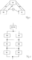
- FIG. 1 shows a 1 of 2 computer system as a block diagram.
- FIG. 2 shows an equivalent circuit diagram for calculating the availability.
- FIG. 1 shows at the top the diagnostic computer DR, which is connected to the two computer units R1 and R2 each via a line report R and a return line acknowledgment Q.
- the main task of the diagnostic computer is to select the active computer unit. If the arbitration were left to the two computer units themselves, there would be a risk that a defective computer unit would not relinquish control or would falsely force control. Furthermore, an activation line is drawn, which leads from the diagnostic computer DR to the left computer R1.
- An inverter 1 is connected to this activation line, the output of which leads to the activation / activation input of the right-hand computer R2.
- This inverter ensures that exactly one computer unit is always active. In principle, it would be possible to control the activation using (different) ports in the diagnostic computer. A defective diagnostic computer could then select both computer units or no computer unit. As will be demonstrated arithmetically below, the isolated inverter circuit in particular causes the high unavailability of the system described.
- the redundancy manager RM is the part of the software in the computer units which has the task of supplying the diagnostic computer with the information which enables the two computer units to be monitored by the diagnostic computer.
- the redundancy manager monitors the messages which are sent from the diagnostic computer to the computer unit, so that the diagnostic computer and the computer unit are mutually checked.
- Another task of the redundancy manager is to create the conditions to enable an orderly switch from the active computer unit to the stand-by computer unit. To do this, the application software on both computer units must be prepared for the switchover. The switchover preparation, the actual switchover by the diagnostic computer and the subsequent re-installation of the two computer units are carried out automatically without external control.
- Communication between the diagnostic computer and the computer unit takes place on the application level between the diagnostic computer software and the redundancy manager.
- Message frames are constantly being exchanged, namely message frames that are sent from a computer unit to the diagnostic computer, reports on line R and message frames from the diagnostic computer to a computer unit, called acknowledgment, on line Q.
- Both the active and the stand-by Redundancy managers send cyclical reports to the diagnostic computer, which contain information about self-test results, commands to the diagnostic computer and states of the computer unit. This information is provided by the Diagnostic computer software evaluated and answered with a receipt to the respective redundancy manager. Analogous to the content of an RM report, this receipt contains self-test results from the diagnostic computer and commands to the redundancy manager.
- the arrival of the messages of the diagnostic manager is checked Regularly monitored over time.
- the diagnostic computer must ensure that the two computer unit active lines are switched over atomically, ie that the two switching times between the active and the passive computer cannot drift apart in time.
- the functional properties between the redundancy manager and the diagnostic manager are identical for both the active and the passive computer.
- the redundancy manager does not evaluate the diagnostic results. This only happens in the diagnostic computer. After the system starts, the diagnostic manager sends a complete set of self-tests or diagnostic results (power-up diagnostics) to the redundancy manager.
- the diagnosis manager cyclically sends the diagnosis results of the respective computer unit to the corresponding redundancy manager.
- results are sent in closed form and then integrated into the reports by the redundancy manager and passed on to the diagnostic computer without being overlooked.
- the communication between the diagnosis and the redundancy manager is monitored over time, ie if no report is received within a specified period of time, an error of the diagnosis manager is accepted and the diagnosis computer is informed accordingly.
Landscapes
- Engineering & Computer Science (AREA)
- Theoretical Computer Science (AREA)
- General Engineering & Computer Science (AREA)
- Quality & Reliability (AREA)
- Physics & Mathematics (AREA)
- General Physics & Mathematics (AREA)
- Computer Hardware Design (AREA)
- Hardware Redundancy (AREA)
Applications Claiming Priority (2)
| Application Number | Priority Date | Filing Date | Title |
|---|---|---|---|
| DE19924241319 DE4241319A1 (de) | 1992-12-09 | 1992-12-09 | Rechnersystem |
| DE4241319 | 1992-12-09 |
Publications (2)
| Publication Number | Publication Date |
|---|---|
| EP0601424A2 true EP0601424A2 (fr) | 1994-06-15 |
| EP0601424A3 EP0601424A3 (fr) | 1995-03-29 |
Family
ID=6474703
Family Applications (1)
| Application Number | Title | Priority Date | Filing Date |
|---|---|---|---|
| EP93119147A Withdrawn EP0601424A3 (fr) | 1992-12-09 | 1993-11-27 | Système d'ordinateur. |
Country Status (2)
| Country | Link |
|---|---|
| EP (1) | EP0601424A3 (fr) |
| DE (1) | DE4241319A1 (fr) |
Cited By (1)
| Publication number | Priority date | Publication date | Assignee | Title |
|---|---|---|---|---|
| WO2015128639A1 (fr) * | 2014-02-27 | 2015-09-03 | Trw Limited | Circuit de commande de pont moteur |
Families Citing this family (1)
| Publication number | Priority date | Publication date | Assignee | Title |
|---|---|---|---|---|
| DE10351019A1 (de) * | 2003-10-31 | 2005-06-30 | P21 - Power For The 21St Century Gmbh | Verfahren zum Steuern und/oder Regeln wenigstens eines Aggregats in einem technischen System sowie technisches System |
Family Cites Families (12)
| Publication number | Priority date | Publication date | Assignee | Title |
|---|---|---|---|---|
| DE2108836A1 (de) * | 1971-02-25 | 1972-09-07 | Licentia Gmbh | Anordnung für ein Doppelrechnersystem |
| DE2407241A1 (de) * | 1974-02-15 | 1975-08-21 | Ibm Deutschland | Verfahren und anordnung zur erhoehung der verfuegbarkeit eines digitalrechners |
| DE2903639A1 (de) * | 1979-01-31 | 1980-08-14 | Bosch Gmbh Robert | Rechnersystem zur steuerung einer vorrichtung in abhaengigkeit von steuersignalen |
| IT1209187B (it) * | 1980-02-11 | 1989-07-16 | Sits Soc It Telecom Siemens | Dispositivo di controllo del corretto funzionamento di una coppia di elaboratori funzionanti uno come riserva calda dell'altro. |
| US4377000A (en) * | 1980-05-05 | 1983-03-15 | Westinghouse Electric Corp. | Automatic fault detection and recovery system which provides stability and continuity of operation in an industrial multiprocessor control |
| IT1209258B (it) * | 1980-08-26 | 1989-07-16 | Sits Soc It Telecom Siemens | Disposizione circuitale atta a gestire lo scambio di dati tra una coppia di elaboratori, operanti secondo il principio master-slave, ed un elaboratore di supporto. |
| IT8003504A0 (it) * | 1980-09-05 | 1980-09-05 | Sits Soc It Telecom Siemens | Apparecchiatura per la gestione delle informazioni ausiliarie inerenti ad un comando centrale di una pluralita'di utenze periferiche e per la diagnosi dello stesso comando centrale |
| IT8024701A0 (it) * | 1980-09-17 | 1980-09-17 | Italtel Spa | Disposizione circuitale atta a rilevare la presenza di malfunzionamenti in un sistema di elaborazione di dati utilizzante un microprocessore di tipo commerciale. |
| JPS6053339B2 (ja) * | 1980-10-09 | 1985-11-25 | 日本電気株式会社 | 論理装置のエラ−回復方式 |
| JPS58221453A (ja) * | 1982-06-17 | 1983-12-23 | Toshiba Corp | 多重系情報処理装置 |
| DE3700986C2 (de) * | 1987-01-15 | 1995-04-20 | Bosch Gmbh Robert | Einrichtung zur Überwachung eines Rechnersystems mit zwei Prozessoren in einem Kraftfahrzeug |
| DE4134207C1 (en) * | 1991-10-16 | 1993-04-01 | Ant Nachrichtentechnik Gmbh, 7150 Backnang, De | Loading double-computer standby system - preparing passive computer for loading and taking new software from data source for entering into memory of active computer |
-
1992
- 1992-12-09 DE DE19924241319 patent/DE4241319A1/de not_active Ceased
-
1993
- 1993-11-27 EP EP93119147A patent/EP0601424A3/fr not_active Withdrawn
Cited By (4)
| Publication number | Priority date | Publication date | Assignee | Title |
|---|---|---|---|---|
| WO2015128639A1 (fr) * | 2014-02-27 | 2015-09-03 | Trw Limited | Circuit de commande de pont moteur |
| CN106170416A (zh) * | 2014-02-27 | 2016-11-30 | Trw有限公司 | 马达桥驱动器电路 |
| CN106170416B (zh) * | 2014-02-27 | 2019-06-21 | Trw有限公司 | 马达桥驱动器电路 |
| US10447196B2 (en) | 2014-02-27 | 2019-10-15 | Trw Limited | Motor bridge driver circuit |
Also Published As
| Publication number | Publication date |
|---|---|
| EP0601424A3 (fr) | 1995-03-29 |
| DE4241319A1 (de) | 1994-06-16 |
Similar Documents
| Publication | Publication Date | Title |
|---|---|---|
| DE3486148T2 (de) | Fehlertolerantes Übertragungssteuersystem. | |
| DE69802535T2 (de) | Aktive fehlererkennung | |
| DE3882216T2 (de) | Nachrichtenübertragungsvorrichtung zwischen mehreren Kraftfahrzeugteilen und einer zentralen Datenverarbeitungseinheit. | |
| DE2701924A1 (de) | Fahrzeugsteuerungseinrichtung | |
| DE69317507T2 (de) | Fehlertolerantes Rechnersystem mit einem in jedem Prozessormodul vorgesehenen Fehlerdetektor | |
| DE2701925A1 (de) | Fahrzeugsteuerungssystem mit hoher zuverlaessigkeit | |
| EP1410577A1 (fr) | Elements reseau destine a un reseau optique ayant tune fonction de securite, en particulier a un reseau optique a topologie annulaire | |
| AT402909B (de) | Verfahren zur gewährleistung der signaltechnischen sicherheit der benutzeroberfläche einer datenverarbeitungsanlage | |
| DE19847986A1 (de) | Einzelprozessorsystem | |
| DE602004007130T2 (de) | Fehlererkennung und unterdrückung in einem tdma-basierten netzknoten | |
| EP0601424A2 (fr) | Système d'ordinateur | |
| EP1469627B1 (fr) | Procédé de transfert sécurisé de données | |
| EP0182134A2 (fr) | Méthode de mise en oeuvre d'un système multicalculateurs à sécurité intrinsèque comportant plusieur circuits inprimés d'entrées/sorties à sécurité non intrinsèque | |
| EP0392328B1 (fr) | Mèthode pour le contrôle permanent des signaux pour l'affichage des informations sur un écran | |
| DE3634019C2 (fr) | ||
| EP1399818B1 (fr) | Procede et dispositif de communication dans un systeme informatique reparti tolerant aux erreurs | |
| DE1966991A1 (de) | Ausfallgesicherte datenverarbeitungsanlage | |
| EP1881652B1 (fr) | Système de bus de terrain composé de noeds avec surveillance de bus intégrée | |
| EP3761179B1 (fr) | Procédé de vérification du fonctionnement d'un processeur par un chien de garde | |
| DE2164686B2 (de) | Datenverarbeitungssystem mit mehreren Funktionseinheiten | |
| WO1990009633A1 (fr) | Procede d'exploitation d'un systeme multicalculateur caracterise par une qualite de signal fiable | |
| DE4303048A1 (en) | Alarm recognition apparatus for redundant layout circuit in radio equipment - has input circuits delaying alarm recognition signals when circuits are switched to be operational systems | |
| WO1997013203A2 (fr) | Procede de maintien du fonctionnement microsynchrone d'unites doublees pour le traitement d'informations | |
| EP0447635B1 (fr) | Procédé de vérification d'un appareil de commande d'affichage d'installations de sécurité pour absence d'erreur | |
| DE19531923B4 (de) | Einrichtung zur Realisierung von safe-life-Funktionen |
Legal Events
| Date | Code | Title | Description |
|---|---|---|---|
| PUAI | Public reference made under article 153(3) epc to a published international application that has entered the european phase |
Free format text: ORIGINAL CODE: 0009012 |
|
| AK | Designated contracting states |
Kind code of ref document: A2 Designated state(s): AT CH ES GB IT LI |
|
| PUAL | Search report despatched |
Free format text: ORIGINAL CODE: 0009013 |
|
| AK | Designated contracting states |
Kind code of ref document: A3 Designated state(s): AT CH ES GB IT LI |
|
| 17P | Request for examination filed |
Effective date: 19950929 |
|
| RAP1 | Party data changed (applicant data changed or rights of an application transferred) |
Owner name: ROBERT BOSCH GMBH |
|
| 17Q | First examination report despatched |
Effective date: 19970506 |
|
| STAA | Information on the status of an ep patent application or granted ep patent |
Free format text: STATUS: THE APPLICATION IS DEEMED TO BE WITHDRAWN |
|
| 18D | Application deemed to be withdrawn |
Effective date: 19971118 |