EP0601431A2 - Communication centre sous-réseaux interconnectés - Google Patents
Communication centre sous-réseaux interconnectés Download PDFInfo
- Publication number
- EP0601431A2 EP0601431A2 EP93119201A EP93119201A EP0601431A2 EP 0601431 A2 EP0601431 A2 EP 0601431A2 EP 93119201 A EP93119201 A EP 93119201A EP 93119201 A EP93119201 A EP 93119201A EP 0601431 A2 EP0601431 A2 EP 0601431A2
- Authority
- EP
- European Patent Office
- Prior art keywords
- packet
- node
- routing
- message
- network
- Prior art date
- Legal status (The legal status is an assumption and is not a legal conclusion. Google has not performed a legal analysis and makes no representation as to the accuracy of the status listed.)
- Withdrawn
Links
Images


Classifications
-
- H—ELECTRICITY
- H04—ELECTRIC COMMUNICATION TECHNIQUE
- H04L—TRANSMISSION OF DIGITAL INFORMATION, e.g. TELEGRAPHIC COMMUNICATION
- H04L45/00—Routing or path finding of packets in data switching networks
- H04L45/02—Topology update or discovery
- H04L45/04—Interdomain routing, e.g. hierarchical routing
-
- H—ELECTRICITY
- H04—ELECTRIC COMMUNICATION TECHNIQUE
- H04L—TRANSMISSION OF DIGITAL INFORMATION, e.g. TELEGRAPHIC COMMUNICATION
- H04L12/00—Data switching networks
- H04L12/66—Arrangements for connecting between networks having differing types of switching systems, e.g. gateways
Definitions
- the present invention relates to a composite communication network of a hierarchical structure including a subnetwork in particular to a composite communication network in which a message set up in a packet and having a destination node indicated therein is transmitted within the communication network.
- routing protocols of a network layer level such as RIP (routing message protocol) or IS-IS have been employed for routing of control messages.
- routing table messages have been changed periodically or for occasional requests for change, and hence a routing table for each node has been updated and routing of each node has been carried out based on the thus-renewed routing table.
- the conventional routing protocol for control messages described above has a problem in that, for example, the RIP protocol is not applicable to a large-scale network because the transmission range of the routing message is limited to only 16 nodes, while with the IS-IS protocol, although its application is not restricted by a network size, the size of the routing message to be communicated between nodes or the size of a routing table to be held by each node is excessively expanded, resulting in an extended time used for routing, because routing of a whole network is controlled by each node. Further, these protocols are prepared without particular consideration to the physical characteristics of a ring type network, that is, a network of a ring type.
- the composite communication network of the present invention has a hierarchical structure including a subnetwork at least in part thereof, and within the communication network, a message set up in a packet and having a destination node indicated therein is transmitted, wherein, a node of the communication network having connection routes which extend in said communication network in three or more than three directions (hereinafter referred to as a gateway node or a GW node) comprises: a first routing table regarding a node which belongs to a layer other than the layer to which the GW node belongs; a first transmission control means which refers to the first routing table and the destination node indicated in said packet for transmitting said packet in accordance with an interlayer transmission protocol; and said GW node and a node other than said GW node of the communication network, comprise: a second routing table related with a node in the layer to which the node belongs; and a second transmission control means which refers to the second routing table and the destination node indicated in said packet for transmitting said packet
- Said subnetwork may comprise a composite communication network which has a ring type structure, a star type structure, a bus type structure, or a combination of these structures.
- Said first transmission control means and/or said second transmission control means may comprise: means for distinguishing whether or not the destination node indicated in said first packet is the same as its own node; and means for introducing a message of said packet and prohibiting transmission of said packet when the destination node is distinguished by said distinguishing means to coincide with its own node.
- Said first transmission control means and second transmission control means may include: means for distinguishing whether or not said packet is for a health check; means for introducing a message of said packet and executing a health check of its own node when the packet for the health check is found by said distinguishing means; and means for sending a trouble signal to a plurality of nodes when abnormality is detected in the result of said health check.
- said first transmission control means and said second transmission control means may comprise means for updating said first routing table and said second routing table according to a message for change when the message for change of routing is included in said message.
- the message for said change may include said trouble message.
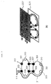
- Fig. 1 is a block diagram showing the construction of a first and a second embodiment of the composite communication network of the present invention.
- Fig. 2 is a network diagram of the composite communication network of Fig. 1.
- Figs. 3(a) and 3(b) are views illustrating the basic operation of the composite communication network of Fig. 1.
- Figs. 4(a) and 4(b) are views showing the construction of the packet format of the first embodiment of the present invention.
- Fig. 4(c) is a view showing the construction of the packet format of the second embodiment of the present invention.
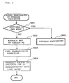
- Fig. 5 is a flow chart showing a processing route of a network layer packet routing application section 104 of Fig. 1.
- Fig. 6 is a flow chart showing a packet processing route of a message processor 112 of Fig. 1.
- Fig. 7 is a flow chart showing a packet processing route of the data link layer packet routing application section 109 of Fig. 1.
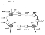
- Fig. 8 is a view showing an example of a network address, that is, an NE address to be defined for a node which is included in the ring network of the first and second embodiments of the present invention.
- Figs. 9(a) and 9(b) are views illustrating the routing operation of the control message in the ring subnetwork of the first and second embodiments, respectively, of the present invention.
- Figs. 10(a) and 10(b) are views illustrating the routing operation when routing is performed from outside the ring subnetwork to and including a target node with reference to the first and second embodiments, respectively, of the present invention.
- Fig. 11 is a flow chart showing a packet processing route of the data link layer packet routing application section of Fig. 1 of the second embodiment of the present invention.
- Fig. 12 is a view showing an example of a routing table of the second embodiment of the present invention.
- Fig. 13 is a view illustrating a method of updating the routing table in an autonomous distribution mode with reference to the second embodiment of the present invention.
- Fig. 1 shows the construction of a first and a second embodiment of a composite communication network of the present invention
- Fig. 2 shows an example of a network of the embodiment of Fig. 1.
- a composite communication network of the first embodiment of the present invention is constructed with a hierarchical structure including a subnetwork at least in part thereof, and within its communication network a message set up in a packet and having a destination node indicated therein is transmitted. Further, a GW node having connection routes extending in the communication network in three or more than three directions has, as shown in Fig. 1, an internal application section 103 and a network layer packet routing protocol section 101.
- the internal application section 103 has a routing message table 113 including a first routing table regarding a node belonging to a layer other than the layer to which said GW node belongs, and the network layer packet routing protocol section 101 comprises a network layer packet routing application section 104 including a first transmission control means (not shown) which refers to the first routing table and a destination node indicated in the packet for transmitting said packet in accordance with an interlayer transmission protocol.
- the internal application section 103 and the network layer packet routing protocol section 101 are also arranged, where the internal application section 103 has a routing message table 113 which includes a second routing table regarding a node of the layer to which the node belongs.
- the network layer packet routing application section 104 has a second transmission control means (not shown) which refers to the second routing table and a destination node indicated in the packet for transmitting said packet in accordance with an intralayer transmission protocol.
- a subnetwork of ring type, star type, bus type, or a combination of these three types is used as the case demands.
- said first transmission control means and said second transmission control means comprise means for distinguishing whether the destination node indicated in the packet is the same as its own node, and means for introducing a message of said packet and prohibiting transmission of said packet when it is distinguished by the distinguishing means that the destination node is the same as its own node.
- a packet (hereinafter referred to as network packet 1) inputted from Ethernet 106 passes through an interface circuit (hereinafter referred to as INF) 105 to be connected to the network layer packet routing application section 104 in the network layer packet routing protocol section 101.
- INF interface circuit
- the network layer packet routing application section 104 Upon receiving the network packet 1, the network layer packet routing application section 104 transmits the packet to a message processor 112 in the internal application section 103 through INF 107 and an internal bus 114 when a target GW node of the packet is destined for its own node.
- the network layer packet routing application section 104 classifies the packet as a network packet 2, extracts a next destination GW node by using an internal network layer routing table, and transmits the packet through INF 110 to a data link layer packet routing application section 109 which corresponds to the direction of the next destination GW node.
- the data link layer packet routing application section 109 transmits it out to a line (control message communication medium) 111 connected thereto.
- the packet is a network packet 2 destined for its own node
- the packet is transmitted to the network layer packet routing application section 104 through INFs 110 and 107.
- the network layer packet routing application section 104 executes the routing operation of the network layer level in the same manner as the processing of the above network packet 1.
- the received packet is a ring packet destined for its own node, it is transmitted to the message processor 112. If the packet is not destined for its own node, it is transmitted to the data link layer packet routing application section 109 on the other side through INF 110 and the internal bus 114 to be sent out.
- the message processor 112 Upon receiving the network packet 1 from the network layer packet routing application section 104, the message processor 112 judges whether it is destined for its own node or not. When the network packet 1 is destined for its own node, the message processor 112 processes the message, but when it is not destined for its own node, the message processor 112 converts it to a ring packet and transmits it to the data link layer packet routing application section 109 in the direction given on the routing message table 113 relative to the target node of the packet. The message processor 112 then sets in the packet an intra-ring-network identifier (NE#) of the target node. When the message processor 112 receives the ring packet from the data link layer packet routing application section 109, the processor processes the message internally.
- NE# intra-ring-network identifier
- the routing message table 113 is in this example provided in the internal application section 103 as shown in Fig. 1, but may also be provided in parallel in the network layer packet routing protocol section 101 or the data link layer packet routing protocol section 102.
- the network in the first embodiment of the present invention is a composite network in which, as shown in Fig. 2, a bus type subnetwork 202, a star type subnetwork 203 and a tree type subnetwork 204 are connected to a ring subnetwork 201.
- a GW node 205 of the ring subnetwork 201 shown in this network example is constructed as described above and shown in Fig. 1.
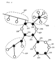
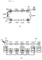
- Fig. 3(a) illustrates an example of interlocked rings in which a ring subnetwork 301 and a ring subnetwork 302 are connected with each other.
- Each of nodes 303 to 307 and 312 having a control message communication medium including three or more than three routes is shown as a GW node and marked with a black circle.
- Fig. 3(b) is a view showing an image of a hierarchical type routing.
- GW nodes 303 to 307 and 312 carry out the routing between GW nodes according to a protocol 320 of the network layer level.
- GW nodes and other nodes 308, 309, 310 and 313 carry out the routing within the ring subnetwork in accordance with a routing protocol 321 of the data link layer level.
- a routing operation 311 which extends from a higher grade operations system (OS) to and including the node 310 shown in Fig. 3(a) is the routing operation according to a hierarchical routing method shown in Fig. 3(b).
- OS operations system
- Fig. 4(a) is a view showing the construction of a format of the network packet 1.
- the network packet 1 is transmitted between GW nodes by means of the control message communication medium outside the ring subnetwork. Assuming that the communication medium is Ethernet, the format of the packet 1 is constituted from an Ethernet header 401, a protocol header 402 of the network layer, and a DATA section 403.
- Fig. 4(b) is a view showing the structure of a format of the network packet 2.
- the routing operation of the network packet 2 is executed with reference to the network layer in the same way as the network packet 1, but its routing area is limited to a range within the ring subnetwork.
- the format of the network packet 2 is constituted from a data link layer protocol header 404, the network layer protocol header 402, and a DATA section 409, and in the network layer protocol header 402, a network address (hereinafter referred to as NW address or NW#) 405 of a target GW node to be used for routing of the network layer is established.
- NW address or NW# network address
- the DATA section 409 has an intra-ring routing header 406 in which a destination network element address (hereinafter referred to as NE address or NE#) 407 to be used in the intra-ring routing operation is established.
- NW# is an address to be used for distinguishing a GW node in the network
- the NE# is an address to be used for distinguishing each ring node in the ring subnetwork.
- Fig. 8 is a view showing an example of the ring subnetwork with the addresses NE#s given thereto, wherein each GW node is given with addresses NW# and NE#.
- Fig. 4(c) is a view showing a format of a ring packet in which routing is established in the data link layer in the ring subnetwork.
- a DATA section 410 has an intra-ring routing header 406 in the same way as the network packet 2.
- Fig. 5 is a flow chart showing a packet processing route of the network layer packet routing application section 104 of the first embodiment of the present invention.
- the network layer packet routing application section 104 Upon receiving the network packet 1 or the network packet 2, the network layer packet routing application section 104 performs mapping of NW# of the target node of the packet and NW# of its own node (S501), and when they coincide with each other, the network layer packet routing application section 104 decides that the received packet is destined for its own node and performs processing to transmit the packet to the message processor 112 (S505).
- the network layer packet routing application section 104 refers to the included routing table (network table) (S502) to extract a message related with the next destination GW node (S503). Then, in order to transmit the packet to the above GW node, the network layer packet routing application section 104 transmits the packet to the corresponding data link layer packet routing protocol section 102 (S504).
- Fig. 6 is a flow chart showing a packet processing route of the message processor of the first embodiment of the present invention.
- the message processor 112 judges whether its own node is the target node of the packet or not (S601).
- the message processor 112 processes the message (S605).
- the message processor 112 searches NE# of the target node (S602) and further finds a direction of transmission toward the target node (S603), and then transmits the ring packet to INF 110 of the data link layer packet routing protocol section 102 corresponding to the above transmission direction (S604).
- Fig. 7 is a flow chart showing a packet processing route of the data link layer packet routing application section of the first embodiment of the present invention.
- the data link layer packet routing application section 109 judges whether the packet is transmitted from the internal bus 114 or received from the control message communication medium 111 in the connection line (S701). When the packet is transmitted from the internal bus 114, the packet is processed for transmitting to the connected line 111 (S702). If the packet is not transmitted from the internal bus 114, the data link layer packet routing application section 109 performs mapping of the destination node NE# of the packet and NE# of its own node (703).
- the data link layer packet routing application section 109 decides that the packet is not destined for its own node and simply processes the packet to transmit it to another data link layer packet routing protocol section (S706).
- S706 another data link layer packet routing protocol section
- the data link layer packet routing application section 109 checks whether it is a network packet 2 (S704) and transmits the packet to the protocol section of the network layer when the packet is the network packet 2 (S707), and, when the packet is a ring packet, it transmits the packet to the message processor 112 (S705).
- Fig. 9(a) and Fig. 9(b) are diagrammatic views illustrating the routing operation of the control message executed within the ring subnetwork of the first embodiment of the present invention.
- Fig. 9(b) illustrates the details of routing applied to the network of Fig. 9(a) from node 901 to node 902, that is, routing is applied to nodes from the transmission source node 901 to the target node 902 with reference to the data link layer.
- Fig. 10(a) and Fig. 10(b) are diagrammatic views illustrating the routing operation applied to the control packet of the first embodiment of the present invention from outside the ring subnetwork to the target node in the ring.
- a network packet 1 (1001) including a control message is transmitted from the transmission source to a GW node 1005 of the ring subnetwork.
- the network packet 1 is then converted to a network packet 2 (1002) at the GW node 1005 and a routing operation is applied to the data link layer from here to a GW node 1006.
- the routing operation of the network layer is terminated at the GW node 1006 and the packet is converted there to a ring packet 1003 and the routing operation of the data link level is then carried out from the GW node 1006 to a target node 1004.
- a second embodiment of the present invention includes a first transmission control means and/or a second transmission control means which correspond to those of the first embodiment and further comprises: means for distinguishing whether a packet is for a health check; means for introducing a message of said packet while executing a health check of its own node when a packet for the health check is found by the distinguishing means; means for sending a trouble signal to a plurality of nodes when abnormality is detected in the result of the health check; and further, said first transmission control means and said second transmission control means comprise means for updating said first routing table and/or said second routing table according to a message when a message (trouble message) for change of routing is included in said message.
- all means and procedures are constructed in the same way as in the first embodiment.
- the present second embodiment will be described with reference to a case in which there are routing protocols of two levels, and in which the level 2 (hereinafter referred to as L2) routing protocol is mounted on the network layer and the level 1 (hereinafter referred to as L1) routing protocol is mounted on the data link layer.
- L2 level 2
- L1 level 1
- the L2 routing protocol will be referred to as a network layer packet routing protocol
- the L1 routing protocol will be referred to as a data link layer packet routing protocol.
- a control packet (L2 packet) inputted from Ethernet 106 passes through INF 105 and is connected to a network layer packet routing application section 104 in a network layer packet routing protocol section 101.
- the network layer packet routing application section 104 receives the L2 packet and finds that the target GW node of the packet is the same as its own node, the network layer packet routing application section 104 transmits the packet to a message processor 112 in an internal application section 103 through INF 107 and an internal bus 114.
- the target GW node of the packet is not the same as its own node, the packet will be transmitted to a data link layer packet routing application section 109 which corresponds to the direction of a next GW node.
- the data link layer packet routing application section 109 Upon receiving the packet, the data link layer packet routing application section 109 sends the packet out to a connection line (control message communication medium) 111.
- the control packet inputted from the line (control message communication medium) 111 to a data link layer packet routing protocol section 102 is judged at the data link layer packet routing application section 109 to determine whether the packet is an L2 packet or not.
- the data link layer packet routing application section 109 transmits the packet to another data link layer packet routing application section 109 through INF 110 and the internal bus 114 if its own node is not the GW node, and transmits the packet to the network layer packet routing application section 104 through INFs 110 and 107 if its own node is the GW node.
- the network layer packet routing application section 104 carries out the routing operation of the network layer level in the same manner as the processing of the above L2 packet.
- a packet is an L1 packet and destined for its own node, it is transmitted to the message processor 112. On the other hand, if the packet is not destined for its own node, the packet is transmitted to another data link layer packet routing application section 109 through INF 110 and the internal bus 114 to be sent out to the line 111.
- the message processor 112 Upon receiving an L2 packet from the network layer packet routing application section 104, the message processor 112 judges whether it is destined for its own node or not. The message processor 112 processes the message if the packet is destined for its own node, and if not destined thereto, converts the L2 packet to an L1 packet and transmits it to the data link layer packet routing application section 109 in the direction indicated in a routing message table 113 relative to the target node of the packet. At this time, an intra-ring-network identifier (NE#) of the target node is set in the packet. Further, when the message processor 112 receives a ring packet from the data link layer packet routing application section 109, it processes the message inside the processor.
- NE# intra-ring-network identifier
- the routing message table 113 shown in Fig. 1 can be placed not only in the internal application section 103, but also in the network layer packet routing protocol section 101 or the data link layer packet routing protocol section 102 being parallel distributed, as in the first embodiment.
- a network of the present second embodiment is a composite network in which the bus type subnetwork 202, star type subnetwork 203 and tree type subnetwork 204 are connected to the ring subnetwork 201 as shown in Fig. 2.
- the GW node 205 of the ring subnetwork 201 illustrated in this network example is constituted as described above and shown in Fig. 1.
- Fig. 3(a) illustrates an example of Interlocked Rings in which a ring subnetwork 301 and a ring subnetwork 302 are connected with each other and Fig. 3(b) is a view showing a representation of routing activity of a hierarchical type.
- the routing method of the present embodiment includes a control message medium which has transmission routes extending in more than three directions in the same way as in the first embodiment.
- GW nodes 303 to 307 and 312 carry out the routing between GW nodes according to a protocol 320 of the network layer level.
- the GW nodes and other nodes 308, 309, 310 and 313 carry out the routing within the ring subnetwork in accordance with a routing protocol 321 of the data link layer level.
- L1 and L2 packets will next be described with reference to Fig. 1 together with the routing algorithm of the network layer packet routing application section 104, the message processor 112, and the data link layer packet routing application section 109 shown in Fig. 1.
- An L2 packet is a packet in which routing is applied between GW nodes. Supposing that the communication medium is Ethernet, the format of the packet is constituted from an Ethernet header, a protocol header of a network layer, and a DATA section.
- Fig. 4(c) illustrates a format of an L1 packet in which routing is established in the data link layer in the ring subnetwork.
- the L1 packet is composed of a protocol header 404 of the data link layer and a DATA section 410.
- the DATA section 410 has an intra-ring routing header 406 wherein a destination NE# 407 and a transmission source NE# 408 in the intra-ring routing are set up.
- the NE# is an address to be used in the ring subnetwork for distinguishing each ring node. In the case of the GW node, it has NW# as an identifier to be monistically defined in the network in addition to NE#.
- Fig. 8 illustrates an example of the ring subnetwork to which NE# is given as described above.
- Fig. 5 is a flow chart showing a packet processing route of the network layer packet routing application section of the second embodiment of the present invention.
- the packet processing operation is such that, upon receiving an L2 packet, the network layer packet routing application section 104 performs mapping of NW# of the target node of the packet and NW# of its own node (S501), and when they are coincident with each other, the network layer packet routing application section 104 decides that the received packet is destined for its own node and performs processing to transmit the packet to the message processor 112 (S505).
- the network layer packet routing application section 104 refers to the routing table (network table) included therein (S502) to extract a message with reference to the next destination GW node (S503). Then, in order to transmit the packet to the above GW node, the network layer packet routing application section transmits the packet to the corresponding data link layer packet routing protocol section 102 (S504).
- Fig. 6 is a flow chart showing a packet processing route of the message processor of the second embodiment of the present invention.
- the message processor 112 judges whether its own node is the target node of the packet or not (S601). When its own node is the target node of the packet, that is, when the target node is destined for its own node, the message processor 112 processes the message (S605). However, when the packet not destined for its own node, the message processor 112 searches NE# of the target node (S602), finds a direction of transmission toward the target node (S603), and then transmits the ring packet to INF 110 of the corresponding data link layer packet routing protocol section 102 (S604).
- Fig. 11 is a flow chart showing a packet processing route of the data link layer packet routing application section of the second embodiment of the present invention.
- the data link layer packet routing application section 109 judges whether the packet is transmitted from the internal bus 114 or received from the control message communication medium in the connection line 111 (S1101). When the packet is transmitted from the internal bus 114, the packet is processed and transmitted to the connection line 111 (S1102). If the packet is not transmitted from the internal bus 114, the data link layer packet routing application section 109 distinguishes whether or not it is an L1 packet or L2 packet (S1103).
- the data link layer packet routing application section 109 judges whether or not its own node is the GW node (1104), and if the judgment indicates that its own node is the GW node, transmits the packet to the protocol INF of the network layer (S1106). If the judgment indicates that its own node is not GW node, it processes and transmits the packet to the protocol INF of another data link layer (S1107). On the other hand, when the packet is judged to be an L1 packet, the data link layer packet routing application section 109 performs mapping of the destination node NE# of the packet and NE# of its own node (S1105).
- the data link layer packet routing application section 109 judges that the packet is not destined for its own node and simply processes the packet to transmit it to other data link layer packet routing protocol section (S1108). By processing packets in this way, the simple relaying operation within a ring type subnetwork is carried out without receiving any assistance from the higher-order layer, and hence, the relay processing speed can be increased. If both NE#s match with each other, the data link layer packet routing application section 109 transmits the packet to the message processor 112 (S1109).
- Fig. 9(a) and Fig. 9(b) are diagrammatic views illustrating the control message routing operation within the ring subnetwork of the first embodiment of the present invention. As shown in Fig. 9(b), routing of the data link layer is performed between and including the transmission source node 901 and the target node 902.
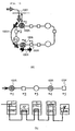
- Fig. 10(a) and Fig. 10(b) are diagrammatic views illustrating the routing operation with reference to the control packet of the second embodiment of the present invention executed in the range outside the ring subnetwork to a target node in the ring.
- Fig. 10(b) illustrates the details of the routing operation executed between and including GW node 1005 and node 1004 of Fig. 10(a).
- An L2 packet (1001) including a control message is transmitted from the transmission source to a GW node 1003 of the ring subnetwork, at which point the network layer routing is terminated and the L2 packet is converted to an L1 packet (1002) and routing is performed to a target node 1004 with reference to the data link layer.
- L1 packet 1002 packet
- directions of transmission are determined referring to the routing tables.
- Fig. 12 is a view showing an example of a routing table of the second embodiment of the present invention.
- This routing table is an example of the routing table to be prepared at node 1 of network 1204 in Fig. 12.
- NE# 1201, status 1202 of the control message communication medium and the packet transmission direction 1203 are established in the order of the nodes connected to the ring (CW direction).
- CW direction the order of the nodes connected to the ring
- a condition of the control message communication medium between its own node and a next node is established. In this example, trouble is generated between node 5 and node 3, so that numeral 1 (troubled) is entered on the message column on the right side of node 5.
- the direction of the packet transmission is established for transmitting the packet toward the target node.
- the CW direction gives the shortest way to transmit the packet from node 1 to node 5, with 00 set in the transmission direction.
- the status of the control message communication medium indicates trouble between nodes 3 and 5, with 01 (CCW direction) set therein.
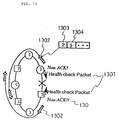
- Fig. 13 is a view showing a method of updating a routing table based on an autonomous distribution mode with reference to the second embodiment of the present invention.
- Each node in the ring network exchanges a health check packet 1301 periodically with neighboring nodes and checks normalcy of the control message communication medium.
- an abnormality such as no reply of the control message communication medium
- an abnormality message 1302 is broadcast along the ring toward the other control message communication medium.
- the abnormality message are recorded at least NE# 1303 of a node which detected trouble and NE# 1304 of a node connected to the other end of the troubled communication medium.
- each node Upon receiving an abnormality message, each node transmits the message to a next node and at the same time introduces the message into the node to revise the routing table for updating.
- processing speed in the composite communication network can be increased and the number of host nodes to be controlled in the routing of the network layer level can be considerably reduced so as to enable the reduction of the contents of the routing table, thereby further increasing processing speed. Furthermore, due to a routing table updating function provided in the network, reliability of the data link layer level can also be improved.
Landscapes
- Engineering & Computer Science (AREA)
- Computer Networks & Wireless Communication (AREA)
- Signal Processing (AREA)
- Small-Scale Networks (AREA)
- Data Exchanges In Wide-Area Networks (AREA)
Applications Claiming Priority (2)
| Application Number | Priority Date | Filing Date | Title |
|---|---|---|---|
| JP4320820A JPH084273B2 (ja) | 1992-11-30 | 1992-11-30 | 複合通信網 |
| JP320820/92 | 1992-11-30 |
Publications (2)
| Publication Number | Publication Date |
|---|---|
| EP0601431A2 true EP0601431A2 (fr) | 1994-06-15 |
| EP0601431A3 EP0601431A3 (fr) | 1994-12-21 |
Family
ID=18125602
Family Applications (1)
| Application Number | Title | Priority Date | Filing Date |
|---|---|---|---|
| EP93119201A Withdrawn EP0601431A3 (fr) | 1992-11-30 | 1993-11-29 | Communication centre sous-réseaux interconnectés. |
Country Status (4)
| Country | Link |
|---|---|
| US (1) | US5452292A (fr) |
| EP (1) | EP0601431A3 (fr) |
| JP (1) | JPH084273B2 (fr) |
| CA (1) | CA2110091C (fr) |
Cited By (5)
| Publication number | Priority date | Publication date | Assignee | Title |
|---|---|---|---|---|
| WO1998009388A1 (fr) * | 1996-08-26 | 1998-03-05 | Motorola Inc. | Procede et appareil d'acheminement de signaux de communication dans un systeme a plusieurs noeuds destinataires |
| EP1009130A1 (fr) * | 1998-12-11 | 2000-06-14 | International Business Machines Corporation | Services de répertoire distribué pour localiser des ressources de réseau dans un trés grand réseau de commutation par paquets |
| GB2347045A (en) * | 1999-02-16 | 2000-08-23 | Hewlett Packard Co | Gateway discovery |
| GB2349038A (en) * | 1999-02-16 | 2000-10-18 | Hewlett Packard Co | Gateway discovery |
| CN112862096A (zh) * | 2021-02-04 | 2021-05-28 | 百果园技术(新加坡)有限公司 | 一种模型训练和数据处理方法、装置、设备及介质 |
Families Citing this family (13)
| Publication number | Priority date | Publication date | Assignee | Title |
|---|---|---|---|---|
| SE9604491L (sv) * | 1996-12-05 | 1998-06-06 | Ericsson Telefon Ab L M | Anordning och förfarande i överföringssystem |
| US6657999B1 (en) * | 1997-03-31 | 2003-12-02 | Texas Instruments Incorporated | Link layer gateway computer for interconnecting ethernet and 1394 networks |
| EP1021757A1 (fr) | 1997-07-25 | 2000-07-26 | Starvox, Inc. | Appareil et procede pour passerelle vocale integree |
| US6332165B1 (en) * | 1997-09-05 | 2001-12-18 | Sun Microsystems, Inc. | Multiprocessor computer system employing a mechanism for routing communication traffic through a cluster node having a slice of memory directed for pass through transactions |
| JP2001197107A (ja) * | 2000-01-07 | 2001-07-19 | Matsushita Electric Ind Co Ltd | アドレス管理装置及びアドレス管理方法 |
| US6907469B1 (en) * | 2000-04-11 | 2005-06-14 | International Business Machines Corporation | Method for bridging and routing data frames via a network switch comprising a special guided tree handler processor |
| US7451072B2 (en) * | 2000-09-29 | 2008-11-11 | Lockheed Martin Corporation | Network simulation system and method |
| US7272139B2 (en) * | 2002-01-11 | 2007-09-18 | International Business Machines Corporation | Fast path routing in a large-scale virtual server computing environment |
| KR100695146B1 (ko) * | 2005-04-12 | 2007-03-14 | 삼성전자주식회사 | 사설망과 공인망이 혼재된 네크워크에서 메시지 전송 방법및 장치 |
| US20080294767A1 (en) * | 2007-05-22 | 2008-11-27 | Sung-Il Hwang | Ubiquitous Wireless Network System, Node Module, and Operation Method of the Node Module |
| US9253061B2 (en) * | 2012-09-12 | 2016-02-02 | International Business Machines Corporation | Tunnel health check mechanism in overlay network |
| US9258208B2 (en) * | 2012-10-30 | 2016-02-09 | Cisco Technology, Inc. | Multiple path availability between walkable clusters |
| US11218559B2 (en) * | 2019-05-28 | 2022-01-04 | Red Hat, Inc. | Asymmetric networking proxy |
Family Cites Families (11)
| Publication number | Priority date | Publication date | Assignee | Title |
|---|---|---|---|---|
| GB8407102D0 (en) * | 1984-03-19 | 1984-04-26 | Int Computers Ltd | Interconnection of communications networks |
| US4706081A (en) * | 1984-12-14 | 1987-11-10 | Vitalink Communications Corporation | Method and apparatus for bridging local area networks |
| US5027350A (en) * | 1988-10-20 | 1991-06-25 | Hewlett-Packard | Method and apparatus for providing a local area network bridge |
| JPH02243039A (ja) * | 1989-03-15 | 1990-09-27 | Nec Corp | 試験制御装置 |
| JP2808694B2 (ja) * | 1989-07-24 | 1998-10-08 | 株式会社日立製作所 | ネットワーク間接続ブリッジ |
| JPH0358644A (ja) * | 1989-07-27 | 1991-03-13 | Fujitsu Ltd | 障害箇所検出方法 |
| JPH0372742A (ja) * | 1989-08-11 | 1991-03-27 | Nec Corp | データ伝送システム |
| JPH03270532A (ja) * | 1990-03-20 | 1991-12-02 | Fujitsu Ltd | フィルタリング制御方式 |
| US5136580A (en) * | 1990-05-16 | 1992-08-04 | Microcom Systems, Inc. | Apparatus and method for learning and filtering destination and source addresses in a local area network system |
| JPH04107029A (ja) * | 1990-08-27 | 1992-04-08 | Mitsubishi Electric Corp | ローカルエリアネットワーク間接続方式 |
| JPH0810875B2 (ja) * | 1991-04-18 | 1996-01-31 | インターナショナル・ビジネス・マシーンズ・コーポレイション | 局所ネットワークを大域ネットワークと接続する方法及び装置 |
-
1992
- 1992-11-30 JP JP4320820A patent/JPH084273B2/ja not_active Expired - Lifetime
-
1993
- 1993-11-26 CA CA002110091A patent/CA2110091C/fr not_active Expired - Lifetime
- 1993-11-29 EP EP93119201A patent/EP0601431A3/fr not_active Withdrawn
- 1993-11-30 US US08/160,023 patent/US5452292A/en not_active Expired - Lifetime
Cited By (7)
| Publication number | Priority date | Publication date | Assignee | Title |
|---|---|---|---|---|
| WO1998009388A1 (fr) * | 1996-08-26 | 1998-03-05 | Motorola Inc. | Procede et appareil d'acheminement de signaux de communication dans un systeme a plusieurs noeuds destinataires |
| EP1009130A1 (fr) * | 1998-12-11 | 2000-06-14 | International Business Machines Corporation | Services de répertoire distribué pour localiser des ressources de réseau dans un trés grand réseau de commutation par paquets |
| GB2347045A (en) * | 1999-02-16 | 2000-08-23 | Hewlett Packard Co | Gateway discovery |
| GB2349038A (en) * | 1999-02-16 | 2000-10-18 | Hewlett Packard Co | Gateway discovery |
| GB2349038B (en) * | 1999-02-16 | 2003-08-13 | Hewlett Packard Co | Gateway discovery |
| GB2347045B (en) * | 1999-02-16 | 2003-09-10 | Hewlett Packard Co | Gateway discovery |
| CN112862096A (zh) * | 2021-02-04 | 2021-05-28 | 百果园技术(新加坡)有限公司 | 一种模型训练和数据处理方法、装置、设备及介质 |
Also Published As
| Publication number | Publication date |
|---|---|
| JPH084273B2 (ja) | 1996-01-17 |
| JPH06296177A (ja) | 1994-10-21 |
| CA2110091A1 (fr) | 1994-05-31 |
| EP0601431A3 (fr) | 1994-12-21 |
| US5452292A (en) | 1995-09-19 |
| CA2110091C (fr) | 1999-10-05 |
Similar Documents
| Publication | Publication Date | Title |
|---|---|---|
| US5452292A (en) | Composite communication network | |
| US5802316A (en) | Routers connecting LANs through public network | |
| US5719861A (en) | Automatic route determination method | |
| EP0163999B1 (fr) | Méthode pour maintenir de bout en bout l'intégrité des données dans un réseau local à multiples anneaux | |
| EP0324277B1 (fr) | Partage de charge distribué | |
| CA2092134C (fr) | Element de reseau a acheminement reparti | |
| US7139835B2 (en) | Communication network based on topographic network devices | |
| US5805818A (en) | System for acknowledging availability of neighbor node using data packet containing data that is ordinarily fowarded to neighbor node | |
| US6873603B1 (en) | MAC address population protocol | |
| JPH05207022A (ja) | ブリッジ様データ転送を可能にする遠隔アドレス方法を用いるルータ | |
| JP3449541B2 (ja) | データパケット転送網とデータパケット転送方法 | |
| US6556584B1 (en) | System and method of communicating non-standardized addresses over a standardized carrier network | |
| US20030016677A1 (en) | Fabric bus architeture | |
| US6765908B1 (en) | System and method for transferring packets in a “connectionless” network | |
| EP1058427B1 (fr) | Procédé et dispositif pour la création d'une table de routage dans un réseau de communications | |
| US7345993B2 (en) | Communication network with a ring topology | |
| US6718396B1 (en) | Network structure method and route determination equipment | |
| JPS61238141A (ja) | 複合ロ−カルエリアネツトワ−ク | |
| US6567856B1 (en) | Deadlock-free routing | |
| JPS63193634A (ja) | ネツトワ−ク接続方式 | |
| US7693154B2 (en) | Transmitter and method of transmission | |
| JP3073962B2 (ja) | 経路選択装置 | |
| JPH088569B2 (ja) | 放送通信方式 | |
| JPH0637764A (ja) | リモートブリッジのルーティング方式及びリモートブリッジ装置 | |
| JPH06224908A (ja) | ネットワークシステム |
Legal Events
| Date | Code | Title | Description |
|---|---|---|---|
| PUAI | Public reference made under article 153(3) epc to a published international application that has entered the european phase |
Free format text: ORIGINAL CODE: 0009012 |
|
| AK | Designated contracting states |
Kind code of ref document: A2 Designated state(s): DE FR GB |
|
| PUAL | Search report despatched |
Free format text: ORIGINAL CODE: 0009013 |
|
| AK | Designated contracting states |
Kind code of ref document: A3 Designated state(s): DE FR GB |
|
| 17P | Request for examination filed |
Effective date: 19941114 |
|
| 17Q | First examination report despatched |
Effective date: 20010510 |
|
| STAA | Information on the status of an ep patent application or granted ep patent |
Free format text: STATUS: THE APPLICATION IS DEEMED TO BE WITHDRAWN |
|
| 18D | Application deemed to be withdrawn |
Effective date: 20030603 |