EP0601564A2 - Douille électrique résistant aux vibrations - Google Patents
Douille électrique résistant aux vibrations Download PDFInfo
- Publication number
- EP0601564A2 EP0601564A2 EP93119799A EP93119799A EP0601564A2 EP 0601564 A2 EP0601564 A2 EP 0601564A2 EP 93119799 A EP93119799 A EP 93119799A EP 93119799 A EP93119799 A EP 93119799A EP 0601564 A2 EP0601564 A2 EP 0601564A2
- Authority
- EP
- European Patent Office
- Prior art keywords
- contact
- receptacle
- section
- electrical receptacle
- upper box
- Prior art date
- Legal status (The legal status is an assumption and is not a legal conclusion. Google has not performed a legal analysis and makes no representation as to the accuracy of the status listed.)
- Granted
Links
Images


Classifications
-
- H—ELECTRICITY
- H01—ELECTRIC ELEMENTS
- H01R—ELECTRICALLY-CONDUCTIVE CONNECTIONS; STRUCTURAL ASSOCIATIONS OF A PLURALITY OF MUTUALLY-INSULATED ELECTRICAL CONNECTING ELEMENTS; COUPLING DEVICES; CURRENT COLLECTORS
- H01R13/00—Details of coupling devices of the kinds covered by groups H01R12/70 or H01R24/00 - H01R33/00
- H01R13/02—Contact members
- H01R13/15—Pins, blades or sockets having separate spring member for producing or increasing contact pressure
- H01R13/18—Pins, blades or sockets having separate spring member for producing or increasing contact pressure with the spring member surrounding the socket
Definitions
- This invention relates to a receptacle for an electrical connector comprising a receiving portion for a pin-like or tab-like complementary contact of a complementary connector on a longitudinal end on a receiving side and a mounting portion on the other longitudinal end, according to the preamble of claim 1.
- Electrical connectors often are situated in an environment where they are exposed to mechanical load caused by shaking or oscillating movement or vibrations and/or stress due to thermal changes. Examples are electrical connectors used in machines or motor vehicles. If such connectors are situated in the engine compartment of a motor vehicle, not only does heavy mechanical load of the above-mentioned kind occur but also high differences in temperature occur especially during wintertime between the motor vehicle at standstill and being driven.
- An electrical receptacle is shown in EP Publication 0 492 479 which is movable longitudinally for use in high vibration atmospheres.
- This receptacle as shown, is mainly for use on a printed circuit board where a mating pin can be inserted through the top of the receptacle, or through the bottom of the receptacle, through the board. For this reason, the contact arms are elongate, to centralize the pin contact point within the length of the receptacle. It is desirable to use a similar terminal for connection to a wire, for use in automotive applications.
- the objects of the invention have been accomplished by providing a receptacle for receiving a complementary pin or tab, where the receptacle portion is resilient in longitudinal direction.
- the receptacle is characterized in that an upper box section is longitudinally movable and connected to said body portion, and resilient contact arms, formed from said upper box section, are reversely bent into said upper box section, having a length no longer than a length of said upper box section, thereby forming a receptacle section.
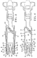
- an electrical receptacle is shown generally at 2 comprising a front mating section 4, a body or mounting portion 6, and a wire terminating section 8.
- An outer spring surrounds the receptacle front portion and is shown generally at 10.
- the inner contact portion is shown as 12 and is generally box shaped in construction, where the base portion 6 includes a base wall 14, side walls 16 and 18 and top wall portions 20 and 22 (Figure 6).
- the cover wall portions 20 and 22 extend upwardly at a web portion 24 to form wall portions 26 and 28, leaving a peripheral slit at 30 thereby forming a moveable box portion 34 having side walls 36 and 38 and a base portion 40.
- the base portion 40 continues upwardly to form a base portion 42 interconnected by a medial web portion 44 to form a further box portion at 45 comprised of base portion 42, side walls 46 and 48 ( Figure 4) and top cover portions 50 and 52.
- the box portion 34 is separated from the box portion 45 via the peripheral slit at 53.
- top cover portions 50 and 52 are continuous to form top cover portion 54 and 55 via a web 56 thereby forming an upper box portion 58.
- the upper box portion 58 is separated from the box portion 45 at peripheral slit 60 thereby allowing the box portions 45 and 58 to be moveable relative thereto about the web portion 56.
- the upper box portion 58 is comprised of a base portion 62 side walls 66 and 68 and the top wall portions 54 and 55.
- Contact arms 70 and 72 ( Figure 4) extend integrally from side wall portions 66 and 68 respectively about bight portions 74 and 76.
- the contact arms 70 and 72 have outward projections forming contact members 78 and 80 opposed from one another and are profiled to engage a mating tab member.
- the contact arms 70 and 72 are formed such that their ends 82 and 84 are positioned within the upper box portion 58.
- the contact arms 70 and 72 further include stop surfaces 86 and 88 which can abut the side walls 66 and 68 respectively to prevent over-stressing or plastically deforming the contact arms 70 and 72.
- the base wall 62 includes a slot 90 ( Figure 4) and openings 92 which, as shown in Figures 4 and 5 extend around into the side wall 66.
- the slot 90 together with the openings 92 define strap portions 96, which will be described in greater detail herein.
- the top cover parts 54 and 55 are connected together by a spot weld at 97, and a second slot 98 is positioned above the weld 97.
- Two further openings are located at 99 which also extend into the side walls 66 and 68, as shown in Figure 5, thereby forming strap portions 100, between the slot 98 and openings 99.
- the outer spring 10 is generally box shaped in nature and overlies the receptacle portion of the inner spring member 12.
- the outer spring member 10 is comprised of a base portion 102 side walls 104, 106 and top cover parts 108, 110. Resilient locking lances 112 and 114 are stamped out of the side walls 104 and 106, respectively as shown in Figure 2 and 3.
- the outer spring member 10 is fixed to the inner contact 12 by way of tab portions 120 and 122 which are sheared from the side walls 104 and 106 and partly from the cover members 108 and 110, being crimped over the top edges of side wall portions 16 and 18, as best shown in Figures 1 and 2.
- the cover parts 108 and 110 are fixed to each other at the front end, for example by spot welding at 124, however this spot weld 124 does not retain the inner spring contact 12 to the outer cover 10.
- box portions 34, 45 and 58 are moveable axially along center line C as shown in Figure 5 towards and away from the base portion 6, within the confines of the outer spring member 10. While the inner spring member 12 is allowed to move axially within the outer spring, stop means must be provided cooperatively between the inner spring member 12 and the outer spring member 10 to prevent over stressing the inner spring member 12.
- the outer spring member 10, and more particularly the side walls 104,106 include half moon shaped projections 125, as shown in Figures 2 and 3 which are formed by shearing lines at 126 ( Figure 2), and thereafter moving the sheet metal into the interior of the outer spring, as viewed in Figure 3, thereby forming a stop surface at the shear line 126 to cooperate with an edge 128 ( Figure 5) on the top box portion 58 to control the extremity of the downward movement of the top box portion 58.
- the outer spring 10 includes curved wing portions 130 and 132 overlying the bight portions 74 and 76, which controls the upper extreme movement of the box member 58.
- the electrical terminal shown in Figures 1-5 can be crimped to a wire via the wire interconnection section 8 and used in an atmosphere containing high vibration, such as for use in an automobile. Due to the axial movement of the terminal contact portion 12 the pin and receptacle can undergo vibration without fear of fretting corrosion between the mating contact surfaces of the tab and contact portions 78 and 80. Also due to the short length of the contact arms 70 and 72, the contact arms are kept within the profile of the top box portion 58 thereby preventing any friction between the surfaces 86 and 88 of the contact arms 70 and 72 during the axial movement of the top box portion 58 during vibration.
- the base portion 62 is slotted at 90 thereby defining the strap portioned 96 which act as further spring members allowing spring action in the strap portions 96.
- the terminal can be conventionally retained in the connector housing by way of the locking lances 112 and 114 as the primary lock, while the curved wing portions 130 and 132 ( Figure 3) of the outer spring 10 provide a flared entry way for a mating tab member.
Landscapes
- Connector Housings Or Holding Contact Members (AREA)
- Coupling Device And Connection With Printed Circuit (AREA)
- Details Of Connecting Devices For Male And Female Coupling (AREA)
- Connecting Device With Holders (AREA)
Applications Claiming Priority (2)
| Application Number | Priority Date | Filing Date | Title |
|---|---|---|---|
| GB9225885 | 1992-12-11 | ||
| GB929225885A GB9225885D0 (en) | 1992-12-11 | 1992-12-11 | Vibration proof electrical receptacle |
Publications (3)
| Publication Number | Publication Date |
|---|---|
| EP0601564A2 true EP0601564A2 (fr) | 1994-06-15 |
| EP0601564A3 EP0601564A3 (fr) | 1995-02-08 |
| EP0601564B1 EP0601564B1 (fr) | 1997-09-10 |
Family
ID=10726459
Family Applications (1)
| Application Number | Title | Priority Date | Filing Date |
|---|---|---|---|
| EP93119799A Expired - Lifetime EP0601564B1 (fr) | 1992-12-11 | 1993-12-08 | Douille électrique résistant aux vibrations |
Country Status (7)
| Country | Link |
|---|---|
| US (1) | US5362262A (fr) |
| EP (1) | EP0601564B1 (fr) |
| JP (1) | JPH07307180A (fr) |
| KR (1) | KR100210956B1 (fr) |
| BR (1) | BR9304995A (fr) |
| DE (1) | DE69313794T2 (fr) |
| GB (1) | GB9225885D0 (fr) |
Cited By (8)
| Publication number | Priority date | Publication date | Assignee | Title |
|---|---|---|---|---|
| US5611717A (en) * | 1994-04-22 | 1997-03-18 | The Whitaker Corporation | Miniature anti-fretting receptacle terminal |
| US5616045A (en) * | 1995-07-14 | 1997-04-01 | Augat Inc. | Squib connector for automotive air bag assembly |
| DE19624088A1 (de) * | 1996-06-17 | 1997-12-18 | Framatome Connectors Int | Steckverbinderhülse |
| US5882224A (en) * | 1996-08-28 | 1999-03-16 | Thomas & Betts International, Inc. | Squib connector socker assembly having shorting clip for automotive air bags |
| US6068526A (en) * | 1996-06-17 | 2000-05-30 | Framatome Connectors International | Connector bushing having an improved central base zone |
| EP0969559A3 (fr) * | 1998-06-29 | 2001-01-31 | The Whitaker Corporation | Contact de prise électrique |
| DE19526738C2 (de) * | 1995-07-21 | 2003-07-24 | Whitaker Corp | Buchsenkontakt mit Überfeder |
| EP1401057A1 (fr) * | 2002-09-18 | 2004-03-24 | Meccanotecnica Codognese S.p.A. | Borne électrique |
Families Citing this family (31)
| Publication number | Priority date | Publication date | Assignee | Title |
|---|---|---|---|---|
| GB9405303D0 (en) * | 1994-03-17 | 1994-04-27 | Amp Gmbh | Electrical contact |
| JP3278017B2 (ja) * | 1994-03-31 | 2002-04-30 | タイコエレクトロニクスアンプ株式会社 | リセプタクルコンタクト |
| JP3216757B2 (ja) * | 1994-06-27 | 2001-10-09 | 矢崎総業株式会社 | 端 子 |
| JP3402435B2 (ja) * | 1997-05-09 | 2003-05-06 | 住友電装株式会社 | プリント基板用コネクタ |
| US6626708B2 (en) | 2001-03-30 | 2003-09-30 | Tyco Electronics Corporation | Single piece spring contact |
| DE10138755A1 (de) * | 2001-08-07 | 2003-02-20 | Bosch Gmbh Robert | Kontaktelement für eine elektrische Steckverbindung |
| SG122836A1 (en) * | 2004-11-29 | 2006-06-29 | Fci Asia Technology Pte Ltd | Compression connector |
| JP2008123913A (ja) * | 2006-11-14 | 2008-05-29 | Auto Network Gijutsu Kenkyusho:Kk | 内導体端子及び同軸コネクタ |
| DE102007049055B3 (de) * | 2007-10-11 | 2009-03-26 | Tyco Electronics Amp Gmbh | Vibrationsdämpfendes Kontaktelement |
| US8366497B2 (en) * | 2009-06-17 | 2013-02-05 | Lear Corporation | Power terminal |
| KR101598633B1 (ko) * | 2009-11-11 | 2016-02-29 | 타이코에이엠피 주식회사 | 커넥터용 단자 |
| DE102012017949A1 (de) * | 2011-09-28 | 2013-03-28 | Sumitomo Wiring Systems, Ltd. | Anschlusspassstück |
| US8951051B2 (en) | 2011-10-10 | 2015-02-10 | Lear Corporation | Connector having optimized tip |
| JP2014007021A (ja) * | 2012-06-22 | 2014-01-16 | Auto Network Gijutsu Kenkyusho:Kk | ソケット端子 |
| EP2690716B1 (fr) * | 2012-07-24 | 2018-05-02 | Delphi Technologies, Inc. | Elément de raccordement électrique |
| DE102014100074B4 (de) | 2014-01-07 | 2020-06-18 | Miele & Cie. Kg | Waschautomat zum Feuchtwaschen |
| JP6238359B2 (ja) * | 2014-04-23 | 2017-11-29 | 日本航空電子工業株式会社 | ソケットコンタクト |
| EP4024617A1 (fr) * | 2014-04-24 | 2022-07-06 | Molex, LLC | Garniture de borne |
| DE102014118688A1 (de) * | 2014-08-21 | 2016-02-25 | Erni Production Gmbh & Co. Kg | Kontaktelement und Steckverbinder |
| US9905953B1 (en) | 2016-09-30 | 2018-02-27 | Slobodan Pavlovic | High power spring-actuated electrical connector |
| DE102016125764A1 (de) * | 2016-12-28 | 2018-06-28 | Lear Corporation | Zweistückige elektrische clean-body-anschlussbuchse |
| US10283895B1 (en) | 2017-12-20 | 2019-05-07 | Lear Corporation | Electrical terminal assembly with split shroud |
| US10396482B2 (en) | 2017-12-20 | 2019-08-27 | Lear Corporation | Electrical terminal assembly with locked spring member |
| CN111937250B (zh) | 2018-02-26 | 2022-09-30 | 皇家精密制品有限责任公司 | 用于高功率应用的弹簧致动式电连接器 |
| WO2019237009A1 (fr) | 2018-06-07 | 2019-12-12 | Royal Precision Products, Llc | Système de connecteur électrique avec composant ressort interne |
| WO2020150399A1 (fr) | 2019-01-15 | 2020-07-23 | Royal Precision Products, Llc | Système de connecteur électrique blindé doté d'un composant de ressort interne |
| DE112020000459T5 (de) | 2019-01-21 | 2021-11-25 | Royal Precision Products, Llc | Stromverteilungsanordnung mit schraubenlosem sammelschienensystem |
| US11721942B2 (en) | 2019-09-09 | 2023-08-08 | Eaton Intelligent Power Limited | Connector system for a component in a power management system in a motor vehicle |
| CN114787815A (zh) | 2019-09-09 | 2022-07-22 | 伊顿智能动力有限公司 | 具有可读和可记录标记的连接器记录系统 |
| TWI734244B (zh) * | 2019-11-04 | 2021-07-21 | 大陸商東莞訊滔電子有限公司 | 電性端子以及電連接器 |
| DE112021003695T5 (de) | 2020-07-29 | 2023-06-29 | Eaton Intelligent Power Limited | Verbindersystem einschliesslich eines verriegelungssystems |
Family Cites Families (5)
| Publication number | Priority date | Publication date | Assignee | Title |
|---|---|---|---|---|
| DE1490493C3 (de) * | 1963-12-02 | 1975-09-18 | Siemens Ag, 1000 Berlin Und 8000 Muenchen | Federelement für Steckverbindungen |
| DE9017536U1 (de) * | 1990-12-28 | 1991-03-21 | Amp Inc., Harrisburg, Pa. | Steckverbindungsbuchse |
| DE4109519A1 (de) * | 1991-03-22 | 1992-09-24 | Grote & Hartmann | Loetkontakt fuer einen kontaktstift |
| DE9106775U1 (de) * | 1991-06-03 | 1991-07-18 | Amp Inc., Harrisburg, Pa. | Elektrischer Steckkontakt |
| DE9106773U1 (de) * | 1991-06-03 | 1991-07-18 | Amp Inc., Harrisburg, Pa. | Elektrischer Steckkontakt |
-
1992
- 1992-12-11 GB GB929225885A patent/GB9225885D0/en active Pending
-
1993
- 1993-11-10 US US08/150,670 patent/US5362262A/en not_active Expired - Fee Related
- 1993-12-08 EP EP93119799A patent/EP0601564B1/fr not_active Expired - Lifetime
- 1993-12-08 DE DE69313794T patent/DE69313794T2/de not_active Expired - Fee Related
- 1993-12-09 BR BR9304995A patent/BR9304995A/pt not_active IP Right Cessation
- 1993-12-09 KR KR1019930026990A patent/KR100210956B1/ko not_active Expired - Fee Related
- 1993-12-09 JP JP5340836A patent/JPH07307180A/ja active Pending
Cited By (11)
| Publication number | Priority date | Publication date | Assignee | Title |
|---|---|---|---|---|
| US5611717A (en) * | 1994-04-22 | 1997-03-18 | The Whitaker Corporation | Miniature anti-fretting receptacle terminal |
| US5616045A (en) * | 1995-07-14 | 1997-04-01 | Augat Inc. | Squib connector for automotive air bag assembly |
| US5746618A (en) * | 1995-07-14 | 1998-05-05 | Augat Inc. | Squib connector for automotive air bag assembly |
| DE19526738C2 (de) * | 1995-07-21 | 2003-07-24 | Whitaker Corp | Buchsenkontakt mit Überfeder |
| DE19624088A1 (de) * | 1996-06-17 | 1997-12-18 | Framatome Connectors Int | Steckverbinderhülse |
| DE19624088C2 (de) * | 1996-06-17 | 1999-02-18 | Framatome Connectors Int | Steckverbinderhülse |
| US6068526A (en) * | 1996-06-17 | 2000-05-30 | Framatome Connectors International | Connector bushing having an improved central base zone |
| US5882224A (en) * | 1996-08-28 | 1999-03-16 | Thomas & Betts International, Inc. | Squib connector socker assembly having shorting clip for automotive air bags |
| US6145193A (en) * | 1996-08-28 | 2000-11-14 | Thomas & Betts International, Inc. | Method of forming a squib connector socket assembly having shorting clip for automotive air bags |
| EP0969559A3 (fr) * | 1998-06-29 | 2001-01-31 | The Whitaker Corporation | Contact de prise électrique |
| EP1401057A1 (fr) * | 2002-09-18 | 2004-03-24 | Meccanotecnica Codognese S.p.A. | Borne électrique |
Also Published As
| Publication number | Publication date |
|---|---|
| EP0601564B1 (fr) | 1997-09-10 |
| DE69313794D1 (de) | 1997-10-16 |
| KR940016996A (ko) | 1994-07-25 |
| GB9225885D0 (en) | 1993-02-03 |
| EP0601564A3 (fr) | 1995-02-08 |
| US5362262A (en) | 1994-11-08 |
| DE69313794T2 (de) | 1998-02-05 |
| KR100210956B1 (ko) | 1999-07-15 |
| JPH07307180A (ja) | 1995-11-21 |
| BR9304995A (pt) | 1994-06-28 |
Similar Documents
| Publication | Publication Date | Title |
|---|---|---|
| EP0601564B1 (fr) | Douille électrique résistant aux vibrations | |
| EP0492479B1 (fr) | Alvéole pour une broche | |
| US5338229A (en) | Electrical contact | |
| US5611717A (en) | Miniature anti-fretting receptacle terminal | |
| US5131853A (en) | Low profile receptacle terminal for soldering to a circuit board | |
| EP0727842A2 (fr) | Borne de puce manobloc | |
| EP0971446B1 (fr) | Contact électrique à douille en deux parties | |
| KR0139698B1 (ko) | 전기 커넥터와, 블레이드 접촉부와 결합시키기 위한 단자 | |
| EP0759213B1 (fr) | Prise universelle a contacts electriques | |
| EP0313253A2 (fr) | Douille à languettes de contact rapportées | |
| EP0795930B1 (fr) | Contact électrique recevant une broche avec une force de contact élevée | |
| US5611716A (en) | Electrical contact having improved secondary locking surfaces | |
| CN114069294B (zh) | 使用滚花图案的抗磨擦/多触点端子 | |
| JP2000516030A (ja) | 電気的端子 | |
| US5857877A (en) | Receptacle container for pressed screen contact pins | |
| US6394834B2 (en) | Insulation displacement contact terminal | |
| JP7753286B2 (ja) | コネクタ製造装置 | |
| US20250279593A1 (en) | Electric cable or electric wire provided with a plug contour for directly plugging into a mating plug | |
| EP0736930A1 (fr) | Contact avec barre de contact à l'intérieur qui est supporté indépendamment | |
| EP4343972A1 (fr) | Système d'interconnexion de puissance | |
| US11381009B2 (en) | Contact and connector | |
| US20250385456A1 (en) | Female terminal for a printed circuit board and printed circuit board arrangement | |
| JPH07176338A (ja) | リセプタクル型コンタクト | |
| JP2000508828A (ja) | 電気プラグコネクタの連結部分 | |
| US20040029457A1 (en) | Contact element for an electrical plug connection |
Legal Events
| Date | Code | Title | Description |
|---|---|---|---|
| PUAI | Public reference made under article 153(3) epc to a published international application that has entered the european phase |
Free format text: ORIGINAL CODE: 0009012 |
|
| AK | Designated contracting states |
Kind code of ref document: A2 Designated state(s): DE ES FR GB IT NL SE |
|
| PUAL | Search report despatched |
Free format text: ORIGINAL CODE: 0009013 |
|
| AK | Designated contracting states |
Kind code of ref document: A3 Designated state(s): DE ES FR GB IT NL SE |
|
| 17P | Request for examination filed |
Effective date: 19950807 |
|
| 17Q | First examination report despatched |
Effective date: 19960613 |
|
| GRAG | Despatch of communication of intention to grant |
Free format text: ORIGINAL CODE: EPIDOS AGRA |
|
| GRAH | Despatch of communication of intention to grant a patent |
Free format text: ORIGINAL CODE: EPIDOS IGRA |
|
| GRAH | Despatch of communication of intention to grant a patent |
Free format text: ORIGINAL CODE: EPIDOS IGRA |
|
| GRAA | (expected) grant |
Free format text: ORIGINAL CODE: 0009210 |
|
| AK | Designated contracting states |
Kind code of ref document: B1 Designated state(s): DE ES FR GB IT NL SE |
|
| PG25 | Lapsed in a contracting state [announced via postgrant information from national office to epo] |
Ref country code: NL Free format text: LAPSE BECAUSE OF FAILURE TO SUBMIT A TRANSLATION OF THE DESCRIPTION OR TO PAY THE FEE WITHIN THE PRESCRIBED TIME-LIMIT Effective date: 19970910 Ref country code: IT Free format text: LAPSE BECAUSE OF FAILURE TO SUBMIT A TRANSLATION OF THE DESCRIPTION OR TO PAY THE FEE WITHIN THE PRE;WARNING: LAPSES OF ITALIAN PATENTS WITH EFFECTIVE DATE BEFORE 2007 MAY HAVE OCCURRED AT ANY TIME BEFORE 2007. THE CORRECT EFFECTIVE DATE MAY BE DIFFERENT FROM THE ONE RECORDED.SCRIBED TIME-LIMIT Effective date: 19970910 |
|
| PGFP | Annual fee paid to national office [announced via postgrant information from national office to epo] |
Ref country code: NL Payment date: 19970919 Year of fee payment: 5 |
|
| REF | Corresponds to: |
Ref document number: 69313794 Country of ref document: DE Date of ref document: 19971016 |
|
| ET | Fr: translation filed | ||
| PGFP | Annual fee paid to national office [announced via postgrant information from national office to epo] |
Ref country code: SE Payment date: 19971202 Year of fee payment: 5 |
|
| PG25 | Lapsed in a contracting state [announced via postgrant information from national office to epo] |
Ref country code: SE Effective date: 19971210 |
|
| PGFP | Annual fee paid to national office [announced via postgrant information from national office to epo] |
Ref country code: ES Payment date: 19971216 Year of fee payment: 5 |
|
| NLV1 | Nl: lapsed or annulled due to failure to fulfill the requirements of art. 29p and 29m of the patents act | ||
| PG25 | Lapsed in a contracting state [announced via postgrant information from national office to epo] |
Ref country code: ES Free format text: LAPSE BECAUSE OF FAILURE TO SUBMIT A TRANSLATION OF THE DESCRIPTION OR TO PAY THE FEE WITHIN THE PRESCRIBED TIME-LIMIT Effective date: 19980325 |
|
| PLBE | No opposition filed within time limit |
Free format text: ORIGINAL CODE: 0009261 |
|
| STAA | Information on the status of an ep patent application or granted ep patent |
Free format text: STATUS: NO OPPOSITION FILED WITHIN TIME LIMIT |
|
| 26N | No opposition filed | ||
| PGFP | Annual fee paid to national office [announced via postgrant information from national office to epo] |
Ref country code: GB Payment date: 20011102 Year of fee payment: 9 |
|
| PGFP | Annual fee paid to national office [announced via postgrant information from national office to epo] |
Ref country code: FR Payment date: 20011203 Year of fee payment: 9 |
|
| REG | Reference to a national code |
Ref country code: GB Ref legal event code: IF02 |
|
| PG25 | Lapsed in a contracting state [announced via postgrant information from national office to epo] |
Ref country code: GB Free format text: LAPSE BECAUSE OF NON-PAYMENT OF DUE FEES Effective date: 20021208 |
|
| GBPC | Gb: european patent ceased through non-payment of renewal fee | ||
| PG25 | Lapsed in a contracting state [announced via postgrant information from national office to epo] |
Ref country code: FR Free format text: LAPSE BECAUSE OF NON-PAYMENT OF DUE FEES Effective date: 20030901 |
|
| REG | Reference to a national code |
Ref country code: FR Ref legal event code: ST |
|
| PGFP | Annual fee paid to national office [announced via postgrant information from national office to epo] |
Ref country code: DE Payment date: 20080131 Year of fee payment: 15 |
|
| PG25 | Lapsed in a contracting state [announced via postgrant information from national office to epo] |
Ref country code: DE Free format text: LAPSE BECAUSE OF NON-PAYMENT OF DUE FEES Effective date: 20090701 |