EP0601574B1 - Zahnbürste - Google Patents
Zahnbürste Download PDFInfo
- Publication number
- EP0601574B1 EP0601574B1 EP93119816A EP93119816A EP0601574B1 EP 0601574 B1 EP0601574 B1 EP 0601574B1 EP 93119816 A EP93119816 A EP 93119816A EP 93119816 A EP93119816 A EP 93119816A EP 0601574 B1 EP0601574 B1 EP 0601574B1
- Authority
- EP
- European Patent Office
- Prior art keywords
- handle
- toothbrush according
- spindle
- brush head
- gear
- Prior art date
- Legal status (The legal status is an assumption and is not a legal conclusion. Google has not performed a legal analysis and makes no representation as to the accuracy of the status listed.)
- Expired - Lifetime
Links
- 230000008878 coupling Effects 0.000 claims abstract description 33
- 238000010168 coupling process Methods 0.000 claims abstract description 33
- 238000005859 coupling reaction Methods 0.000 claims abstract description 33
- 230000033001 locomotion Effects 0.000 claims abstract description 12
- 238000003780 insertion Methods 0.000 claims description 19
- 230000037431 insertion Effects 0.000 claims description 19
- 230000005540 biological transmission Effects 0.000 claims description 14
- 239000011324 bead Substances 0.000 claims description 6
- 230000001154 acute effect Effects 0.000 claims description 4
- 238000010276 construction Methods 0.000 claims 1
- 239000000463 material Substances 0.000 description 6
- 239000000470 constituent Substances 0.000 description 3
- 238000004140 cleaning Methods 0.000 description 2
- 230000008719 thickening Effects 0.000 description 2
- 229910000639 Spring steel Inorganic materials 0.000 description 1
- 238000005452 bending Methods 0.000 description 1
- 230000003247 decreasing effect Effects 0.000 description 1
- 230000000694 effects Effects 0.000 description 1
- 239000011796 hollow space material Substances 0.000 description 1
- 238000001746 injection moulding Methods 0.000 description 1
- 230000002035 prolonged effect Effects 0.000 description 1
- 238000000926 separation method Methods 0.000 description 1
- 238000003466 welding Methods 0.000 description 1
Images

Classifications
-
- A—HUMAN NECESSITIES
- A46—BRUSHWARE
- A46B—BRUSHES
- A46B5/00—Brush bodies; Handles integral with brushware
- A46B5/0095—Removable or interchangeable brush heads
-
- A—HUMAN NECESSITIES
- A46—BRUSHWARE
- A46B—BRUSHES
- A46B13/00—Brushes with driven brush bodies or carriers
-
- A—HUMAN NECESSITIES
- A46—BRUSHWARE
- A46B—BRUSHES
- A46B7/00—Bristle carriers arranged in the brush body
- A46B7/04—Bristle carriers arranged in the brush body interchangeably removable bristle carriers
-
- A—HUMAN NECESSITIES
- A46—BRUSHWARE
- A46B—BRUSHES
- A46B7/00—Bristle carriers arranged in the brush body
- A46B7/04—Bristle carriers arranged in the brush body interchangeably removable bristle carriers
- A46B7/046—Threaded or screw connections for bristle carriers
-
- A—HUMAN NECESSITIES
- A46—BRUSHWARE
- A46B—BRUSHES
- A46B2200/00—Brushes characterized by their functions, uses or applications
- A46B2200/10—For human or animal care
- A46B2200/1066—Toothbrush for cleaning the teeth or dentures
Definitions
- the invention relates to a toothbrush consisting of a handle with a coupling end, and of a brush head with a coupling end, it being possible for the brush head to be firmly but releasably connected to the handle by engagement of their coupling ends.
- a toothbrush of this type is known from EP 0,326,363 A1.
- the brush handle has a conical shape at its front end and the rear end of the brush head facing the brush handle has a recess corresponding to the conical end of the brush handle.
- the cone on the brush handle is provided with an annular bead which engages in an annular groove in the recess of the brush head and thus forms a snap-in holding device which fixes the brush head on the brush handle in the axial direction.
- Longitudinal ribs provided on the cone engage in corresponding longitudinal grooves in the recess of the brush head in order to provide a connection which is fixed in terms of rotation.
- the invention is based on the object of improving a toothbrush of the known generic type stated, in such a way that the brush head is firmly clamped in the axial direction in its connection to the brush handle. As a result, a hygienically satisfactory connection between the brush head and the handle is to be ensured. Furthermore, when positioning the bristles of the brush head on the teeth at the place to be treated, a correspondingly secure grip in the hand holding the brush is to be imparted to the user. In this case, the toothbrush is to be easy to handle and quick to assemble for the user.
- the invention is characterised by
- the gearing is preferably a speed-transforming transmission whose driving gear is coupled to the actuating member and whose output gear meshes with a pinion which is formed by the inner end of the spindle.
- the driving gear of the speed-transforming transmission may be an inner gear. In this case, it is expediently mounted with its cylindrical circumferential surface in a sliding bearing, formed by the handle, so as to be rotatable and fixed against axial movement.
- the driving gear of the speed-transforming transmission can also be an outer gear. In this case, it can have a shaft end which is mounted rotatably but axially non-movably in a bracket formed by the handle approximately parallel to the pinion of the spindle.
- the coupling of the actuating member to the speed-transforming transmission advantageously consists of a bevel gearing whose driving bevel gear is firmly connected to the actuating member and whose output bevel gear forms a unit with the driving gear of the speed-transforming transmission.
- the driving bevel gear may be provided with a shaft end which is mounted rotatably transversely to the longitudinal axis of the handle in a side wall thereof.
- a ring gear may be located with spacing coaxially opposite the driving bevel gear and be provided on the end side facing away from the driving bevel gear with a shaft end which engages rotatably in a sliding bearing of a second side wall of the handle located opposite the first side wall.
- the driving bevel gear is advantageously constructed as an integral constituent of the actuating member.
- the actuating member may be a lever whose swivel axis is formed by the shaft ends of the driving bevel gear and the ring gear.
- the lever in its position which locks the brush head, the lever may fill an opening in an inside wall of the handle, such that the outside of the lever is flush with the outer surface of the handle on its inside or underside.
- the end of the lever facing away from the neck of the handle preferably has on the inside of said lever a lever arm whose forked, free end is formed by the driving bevel gear and the ring gear.
- the lever arm preferably encloses an acute angle which opens towards the handle neck.
- the spindle is expediently provided with a guiding spindle which is mounted with screw motion in a threaded bearing inside the neck of the handle.
- the guiding spindle may be arranged on a central longitudinal portion of the spindle.
- longitudinal portions at the two ends of the spindle may have a smooth outer surface and be mounted rotationally and axially displaceably in each case in a sliding bearing in the neck of the handle.
- the end of the spindle mounted in the neck may advantageously be provided with a thread corresponding to a thread in an insertion opening in the coupling part of the brush head, the thread being arranged in the bottom of the insertion opening of the brush head.
- the neck of the handle is advantageously provided with a socket whose length and cross-section correspond approximately to the depth and the cross-section of the insertion opening in the brush head.
- the plug-in connection for the coupling parts of the brush head and of the handle is provided with a centring device.
- Said centring device preferably consists of a non-round cross-section of the insertion end on the handle and of a corresponding cross-section of the insertion opening in the brush head.
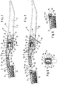
- Figure 1 shows a plastic toothbrush 20 which consists of a handle 22 and a brush head 24 with a bristle zone 26.
- a neck 28 of the handle 22 has a coupling end 30.
- the brush head 24 has a coupling end 32.
- the brush head 24 and the handle 22 are connected firmly but releasably to one another by engagement of the two coupling ends 30, 32.
- the handle 22 and its neck 28 consist of a hollow box profile 34 with an outside wall 36, an inside wall 38, a side wall 40 on the left and a side wall 42 on the right in Figure 5.
- a front longitudinal portion of the inside wall 38 extending up to the handle neck 28 has an opening 44 which is filled by an actuating member 46 which may be constructed as a lever 48 ( Figures 1, 2 and 5).
- the end of the lever 48 facing away from the handle neck 28 has on the inside a lever arm 50 which, with the longitudinal axis of the lever 48, forms an acute angle which opens in the direction of the handle neck 28.
- the inner end of the lever arm 50, protruding into the hollow space of the box profile 34, is branched.
- the branch consists of a ring gear 52 and a driving bevel gear 54 of a bevel gearing 68.
- the ring gear 52 and the driving bevel gear 54 are arranged spaced apart on a common imaginary axis 56 which extends at a central height along the side walls 40, 42 of the box profile 34 perpendicular thereto.
- the ring gear 52 is formed integrally with a shaft end 58 on its side facing away from the driving bevel gear 54.
- the inside of the side wall 42 of the box profile 34 located opposite the shaft end 58 is provided with a sliding bearing 60 which consists of a circular-cylindrical depression in which the shaft end 58 of the ring gear 52 engages rotatably.
- the driving bevel gear 54 is likewise integrally constructed with a shaft end 62 on its side facing away from the ring gear 52.
- the inside of the left side wall 40 of the box profile 34 located opposite the shaft end 62 has a sliding bearing 64 which is constructed coaxially opposite and corresponding to the sliding bearing 60.
- the shaft end 62 of the driving bevel gear 54 engages rotatably in said sliding bearing 64. Consequently, the two shaft ends 58, 62 of the ring gear 52 and driving bevel gear 54 form a swivel axis for the lever 48, said swivel axis being coaxial with the imaginary axis 56, and the ring gear 52 and the driving bevel gear 54 executing a rotary movement when the lever 48 is swivelled.
- the bevel gearing 68 is formed by the driving bevel gear 54 with an output bevel gear 66.
- the output bevel gear 66 is arranged on the end side of an inner gear 70 facing away from the handle neck 28 and forms a plastic part with said inner gear.
- the inner gear 70 is the driving gear for a pinion 72 and, with the latter, forms a speed-transforming transmission 74 for a spindle 76.
- the inner gear 70 has a smooth cylindrical circumferential surface 71 and is mounted rotatably, but axially non-displaceably in a sliding bearing 78 whose imaginary axis 80 runs approximately parallel to the longitudinal axis of the handle 22.
- the sliding bearing 78 is arranged in the region of the front end of the handle 22 behind the handle neck 28 and surrounds the inner gear 70 in the manner of a bracket or ring.
- the sliding bearing 78 is formed integrally with the handle 22 from plastic material.
- the inner gear 70 is of cup-shaped design, a cylindrical cutout 82, coaxial with the axis of rotation 80 of said inner gear, facing the handle neck 28 and the cylindrical wall of the cutout 82 being provided with an internal tooth gearing 84.
- the pinion 72 forms the inner end of the spindle 76 and extends only over a length thereof which is dimensioned to be slightly larger than the axial depth of the cutout 82 of the inner gear 70 having the internal tooth gearing 84.
- the front end of the pinion 72 forming the inner end of the spindle 76 is arranged with a greater or lesser axial spacing from the bottom of the cutout 82 of the inner gear 70 depending on whether the spindle 76 is in its position retracted into the handle 22 or its position moved out of the handle.
- a longitudinal portion 86 of the spindle 76 is provided ahead of the pinion 72 in the direction of the brush head 24.
- the spindle 76 With this longitudinal portion 86, whose diameter corresponds approximately to that of the pinion 72, the spindle 76 is supported axially movably and rotatably in a sliding bearing 88 which, in turn, is produced integrally with the handle 22 from plastic material.
- the sliding bearing 88 is arranged in the vicinity of the inside of the outside wall 36 of the handle 22, such that the longitudinal portion 86 and the pinion 72 are disposed with slight spacing from the inside of the outside wall 36 approximately parallel to the latter.
- the sliding bearing 88 forms an abutment for the pinion 72 which, as a result of the described position of the rear end of the spindle 76, engages in the internal tooth gearing 84 of the inner gear 70 at that point at which the inner gear 70 assumes the smallest spacing from the outside wall 36.
- the longitudinal portion 86 having smooth walls is, of course, dimensioned to be of such a length that the spindle 76 is also mounted satisfactorily in any of its end positions. Since the sliding bearing 88 has a convex bearing surface in cross-section, as shown in Figures 1 and 2, the longitudinal portion 86 having smooth walls is supported substantially only on one line of contact with the least possible friction.
- the spindle 76 is curved so that it can adapt to the physiologically related and therefore desired curvature of the handle neck 28.
- the spindle 76 is produced from flexible material which may preferably be plastic material or even spring steel.
- the flexibility of the spindle 76 is assisted by the fact that the diameter of the circular cross-section of the spindle 76 is reduced over a substantial part of its length in relation to the longitudinal portion 86 and the pinion 74.
- This flexible main longitudinal portion is denoted by reference numeral 90; its curved longitudinal portion is denoted by 92 and is situated with slight axial spacing from the smooth-walled longitudinal portion 86 of the spindle 76.
- the main longitudinal portion 90 has a circular cross-section and is likewise constructed with smooth walls.
- the main longitudinal portion 90 of the spindle 76 is provided with a guiding spindle 100 whose coarse-pitch thread is mounted with screw motion in a corresponding internal thread of a threaded bearing 102 in the handle neck 28.
- the coarse-pitch thread allows a relatively large axial movement of the spindle 76 with, in contrast, a relatively small angle of rotation of the spindle 76 of preferably less than 180°.
- the threaded bearing 102 is produced integrally with the handle neck 28 from plastic material.
- One end 94 of the main longitudinal portion 90 of the spindle 76 is once again mounted axially displaceably and rotatably in a sliding bearing 96 which is formed by the front end of the handle neck 28 and a socket 98 constructed uniformly with the latter.
- the sliding bearing 96 thus extends over a substantial length, by means of which a satisfactory, precise guiding of the spindle 76 is ensured, which in turn is important for a secure attachment or fastening of the brush head 24 to the handle 22.
- the front end 94 of the main longitudinal portion 90 of the spindle 76 has an outer end 104 which, in the assembled state of the toothbrush 20 in Figure 1, protrudes out of the socket 98 of the coupling end 30 of the handle neck 28 but, in the disassembled state of the toothbrush 20 according to Figure 2, is arranged and protected inside the socket 98.
- the outer end 104 of the spindle 76 is provided with a thread 106 whose pitch corresponds to that of the coarse-pitch thread of the guiding spindle 100.
- the socket 98 is greatly decreased or reduced in the cross-section in relation to the coupling end 30 of the handle neck 28 which is tapered towards the brush head 24, such that an annular shoulder 108 is formed. Directly ahead of the shoulder 108, the socket 98 is provided with an annular lock-in groove 110 ( Figures 2 and 6).
- the coupling end 32 of the brush head 24 has a thickening 112, such that two longitudinal rows of bristles are dimensioned to be shorter than the other bristles in increasing stages towards the rear end of the bristle zone. Since the shorter bristles are more resistant to bending, a better cleaning effect can be achieved with this rear, central region of the bristle zone over a prolonged period, which is facilitated, inter alia, by the arrangement of an insertion opening 114 in the end side facing the handle neck 28. In contrast, the longitudinal rows of bristles on the two outer sides of the bristle zone are of equal length, that is to say not shortened, over the entire length of the bristle zone. This allows gentle cleaning of the gum pockets.
- the inside wall of the insertion opening 114 is provided in the region of the opening edge of the latter with an annular lock-in bead 116.
- the depth of the insertion opening 114 is adapted to the length of the socket 98.
- the cross-sections of the socket 98 and of the insertion opening 114 are matched to one another precisely.
- In the bottom 115 of the insertion opening 114 there is a threaded bore 118 whose thread is likewise a coarse-pitch thread which corresponds to the thread 106 at the outer end 104 of the spindle 76.
- the threaded bore 118 has a greater depth in comparison to the length of the thread 106, such that the brush head 24 can be clamped firmly in the axial direction against the neck 28 of the handle 22 by means of the screw connection of its threaded bore 118 to the thread 106 at the outer, front end 104 of the spindle 76 ( Figure 1).
- the lock-in groove 110 of the socket 98 and that of the lock-in bead 116 of the insertion opening 114 serve the purpose of producing a locking resistance which is perceptible for the user of the toothbrush and which, when it is overcome in the insertion direction, shows the user that the brush head 24 can be screwed to the handle 22 by swivelling the lever 48 from the unlocking position shown in Figure 2 into the locking position illustrated in Figure 1 (see also Figure 6).
- the screw connection has been released by swivelling the lever 48 from the locking position shown in Figure 1 into the unlocking position illustrated in Figure 2, the fact that the locking resistance has been overcome indicates the complete separation of the brush head 24 from the handle 22.
- FIGS 3 and 4 show a second embodiment of a toothbrush 220 in which a 2 is placed in front of the reference numerals for parts which are similar to parts of the toothbrush in Figures 1 and 2.
- This second embodiment differs from the first embodiment in Figures 1 and 2 only by a speed-transforming transmission 274 having an outer gear 270 and being connected downstream of a bevel gearing 268.
- a pinion 272 of a spindle 276 is arranged between the inside of an outside wall 236 of a handle 222 and the outer gear 270 and engages in its end-face tooth gearing 284.
- an output bevel gear 266 is mounted as an integral constituent of the outer gear 270 firmly on its front side facing away from the handle neck 228.
- the front side of the outer gear 270 facing the handle neck 228 has a shaft end 271 whose free end has a plate-type widening 273.
- the shaft end 271 extends in the longitudinal direction of the handle 222 and is mounted rotatably, but axially non-displaceably in a sliding bearing 278.
- the sliding bearing 278 is formed by a bracket 275 which in turn is an integral constituent of the handle 222.
- the bracket 275 is part of a sliding bearing 286 for a longitudinal portion 288, having smooth walls, of the spindle 276 which is guided snugly along the inside of the outside wall 236, as shown in Figures 1 and 2.
- Figures 7a, 7b and 7c illustrate different possibilities of centring the brush head 224 on the handle 222.
- the cross-section of the socket 298 and its lock-in groove 210 may have a rectangular contour 120 which is rounded at the corners and whose side edges 122, 124 enclose an acute angle which opens upwards.
- the upper and lower edges 126, 128 are only slightly curved outwards.
- the cross-section of the socket 298 has a horizontal, upper side edge 130 to which two opposite side edges 132, 134 run at right angles.
- a lower side edge 136 is curved outwards.
- Figure 7c shows a circular cross-section 138 of the socket 298 which has an axial centring shoulder 140.
- the insertion opening 214 in Figure 4 is provided on its front side with an axial cutout (not illustrated) which receives the centring shoulder 140 when the coupling ends 230, 232 are plugged into one another and fixes the brush head 224 on the handle 222 securely against rotation. Accordingly, in all the cases described, an attachment of the brush head 24 or 224 to the handle 22 or 222 is achieved which is secured against relative rotation and axial movement of said brush head.
- the handle 22 or 222 is expediently made by injection moulding from two symmetrical semi-shells which are connected to one another by bonding or welding in the region of the longitudinal centre plane of the handle.
- toothbrush according to the invention allows rapid and reliable secure and exchange of a brush head on the handle, secure, satisfactory alignment of the brush head on the handle being achieved.
- An essential prerequisite for this purpose is formed by the relatively large translation of the swivel movement of the lever into a rapid screw motion of the spindle by means of its coarse-pitch thread.
Landscapes
- Brushes (AREA)
Claims (23)
- Zahnbürste, bestehend aus einem Handgriff, dessen Griffhals ein Kupplungsende aufweist, und einem Bürstenkopf mit einem Kupplungsende, wobei der Bürstenkopf mit dem Handgriff durch Ineinandergreifen ihrer Kupplungsenden fest, aber lösbar verbunden werden kann,
gekennzeichnet durchein Betätigungsorgan (46), das an dem Handgriff (22) beweglich befestigt ist;ein Getriebe (68, 74), das innerhalb des Handgriffs (22) angeordnet ist und ein Antriebsrad (54), das mit dem Betätigungsorgan (46) fest verbunden ist, sowie ein Antriebsrad (70) aufweist;eine Spindel (76), die im Handgriff (22) axial beweglich und drehbar gelagert ist, wobei das eine Ende der Spindel (76) innerhalb des Handgriffs (22) mit dem Antriebsrad (70) des Getriebes (68, 74) drehbeweglich verbunden ist und das andere Ende der Spindel (76) im Kupplungsende (30) des Handgriffs (22) gelagert ist und ein erstes Vorrichtungsteil zur lösbaren Verbindung des Handgriffs (22) mit dem Bürstenkopf (24) aufweist;ein zweites Vorrichtungsteil im Kupplungsende (32) des Bürstenkopfes (24) zur lösbaren Verbindung mit dem ersten Vorrichtungsteil am anderen Ende der Spindel (76). - Zahnbürste nach Anspruch 1, dadurch gekennzeichnet, daß das Getriebe (68; 74) ein Übersetzungsgetriebe (74) aufweist, dessen Antriebsrad (70) mit dem Betätigungsorgan (46) beweglich gekoppelt ist und dessen Abtriebsrad ein Zahnritzel (48) ist, welches das innere Ende der Spindel (76) bildet.
- Zahnbürste nach Anspruch 2, dadurch gekennzeichnet, daß das Antriebsrad des Übersetzungsgetriebes (74) ein Innenrad (70) ist.
- Zahnbürste nach Anspruch 3, dadurch geknnzeichnet, daß das Innenrad (70) des Übersetzungsgetriebes (74) eine glattzylindrische Umfangsfläche (71) aufweist, mit welcher das Innenrad (70) in einem Gleitlager (60) drehbar, aber axial unverschieblich gelagert ist.
- Zahnbürste nach Anspruch 2, dadurch gekennzeichnet, daß das Antriebsrad des Übersetzungsgetriebes (274) ein Außenrad (270) ist.
- Zahnbürste nach Anspruch 5, dadurch gekennzeichnet, daß das Außenrad (270) einen Wellenstumpf (271) aufweist, der etwa parallel zum Zahnritzel (272) der Spindel (276) in einer Konsole (275) drehbar, aber axial unverschieblich gelagert ist.
- Zahnbürste nach Anspruch 2, dadurch gekennzeichnet, daß die Kopplung des Betätigungsorgans (46) mit dem Übersetzungsgetriebe (74; 274) aus einem Kegelradgetriebe (68; 268) besteht, dessen Antriebskegelrad (54) mit dem Betätigungsorgan (46) fest verbunden ist.
- Zahnbürste nach Anspruch 7, dadurch gekennzeichnet, daß das Antriebskegelrad (54) mit einem Wellenstumpf (62) versehen ist, der quer zur Längsachse des Handgriffs (22) in einer Seitenwand (40) desselben drehbar gelagert ist.
- Zahnbürste nach Anspruch 8, dadurch gekennzeichnet, daß ein Tellerrad (52) dem Antriebskegelrad (54) im Abstand koaxial gegenüberliegt und an der dem Antriebskegelrad (54) abgekehrten Stirnseite mit einem Wellenstumpf (58) versehen ist, der in ein Gleitlager (60) an der Innenseite der anderen Seitenwand (42) des Handgriffs (22) drehbar eingreift.
- Zahnbürste nach Anspruch 9, dadurch gekennzeichnet, daß das Antriebskegelrad (54) und Tellerrad (52) mit dem Betätigungsorgan (46) einteilig ausgebildet sind.
- Zahnbürste nach einem der Ansprüche 7 bis 10, dadurch gekennzeichnet, daß das Betätigungsorgan (46) ein Hebel (48) ist, dessen Schwenkachse (56) von dem Antriebskegelrad (54) und Tellerrad (52) gebildet ist.
- Zahnbürste nach Anspruch 11, dadurch gekennzeichnet, daß der Hebel (48) in seiner den Bürstenkopf (24) verriegelnden Stellung eine Durchbrechung (44) in einer Innenwand (38) des Handgriffs (22) ausfüllt und das dem Griffhals (28) abgekehrte Ende an seiner Innenseite einen Hebelarm (50) aufweist, an dessen gabelförmigem Ende das Antriebskegelrad (54) und das Tellerrad (52) angeordnet sind.
- Zahnbürste nach Anspruch 12, dadurch gkennzeichnet, daß der Hebel (48) und dessen Hebelarm (50) einen spitzen Winkel bilden, der sich zum Griffhals (28) hin öffnet.
- Zahnbürste nach Anspruch 1, dadurch gekennzeichnet, daß die Spindel (76) mit einer Leitspindel (100) versehen ist, die in einem Gewindelager (102) innerhalb des Griffhalses (28) des Handgriffs (22) schraubbeweglich gelagert ist.
- Zahnbürste nach Anspruch 14, dadurch gekennzeichnet, daß das Gewinde (100) auf einem mittleren Längenbereich der Leitspindel (76) angeordnet ist.
- Zahnbürste nach Anspruch 14 oder 15, dadurch gekennzeichnet, daß die Enden der Spindel (76) in je einem Gleitlager (78, 88) innerhalb des Handgriffs (22) und des Griffhalses (28) gelagert sind.
- Zahnbürste nach Anspruch 1 oder einem folgenden, dadurch gekennzeichnet, daß das Vorrichtungsteil an dem im Kupplungsende (30) des Handgriffs (22) gelagerten Ende der Spindel (76) zur Verbindung mit dem Bürstenkopf (24) aus einem Schraubgewinde (106) besteht.
- Zahnbürste nach Anspruch 17, dadurch gekennzeichnet, daß das Schraubgewinde (106) an dem im Kupplungsende (30) des Handgriffs (22) gelagerten Ende ein Steilgewinde ist.
- Zahnbürste nach Anspruch 1 oder einem der folgenden, dadurch gekennzeichnet, daß das Kupplungsende (30) am Griffhals (28) des Handgriffs (22) eine Steckbuchse (98) ist, deren Querschnitt kleiner als derjenige des Griffhalses (28) bemessen ist.
- Zahnbürste nach Anspruch 19, dadurch gekennzeichnet, daß die Steckbuchse (98) mit einem Teil einer Zentriervorrichtung für den Bürstenkopf (24) am Handgriff versehen ist.
- Zahnbürste nach Anspruch 1 oder einem der folgenden, dadurch gekennzeichnet, daß das Kupplungsende (32) des Bürstenkopfes (24) eine Einstecköffnung (114) aufweist, deren Querschnitt und Tiefe dem Querschnitt und der Länge der Steckbuchse (98) angepaßt sind.
- Zahnbürste nach Anspruch 1 oder einem der folgenden, dadurch gekennzeichnet, daß der Vorrichtungsteil am Kupplungsende (32) des Bürstenkopfes (24) zur Verbindung desselben mit dem Handgriff (22) aus einer Gewindebohrung (118) besteht, die im Boden der Einstecköffnung (114) vorgesehen ist und deren Innengewinde dem Schraubengewinde (106) der Steckbuchse (98) angepaßt ist.
- Zahnbürste nach einem der Ansprüche 19 bis 22, dadurch gekennzeichnet, daß die Steckbuchse (98) an ihrem Vorderende einen ringförmigen Rastwulst (110) aufweist und die Einstecköffnung (114) an ihrem Öffnungsrand mit einem ringförmigen, radial nach innen vorstehenden Rastwulst versehen ist, derart, daß die Steckbuchse (98) nur unter fühlbarem Rastwiderstand in die Einstecköffnung (114) einsetzbar und aus dieser herausbewegbar ist.
Applications Claiming Priority (2)
| Application Number | Priority Date | Filing Date | Title |
|---|---|---|---|
| DE4241468A DE4241468C2 (de) | 1992-12-09 | 1992-12-09 | Zahnbürste |
| DE4241468 | 1992-12-09 |
Publications (2)
| Publication Number | Publication Date |
|---|---|
| EP0601574A1 EP0601574A1 (de) | 1994-06-15 |
| EP0601574B1 true EP0601574B1 (de) | 1997-05-28 |
Family
ID=6474785
Family Applications (1)
| Application Number | Title | Priority Date | Filing Date |
|---|---|---|---|
| EP93119816A Expired - Lifetime EP0601574B1 (de) | 1992-12-09 | 1993-12-08 | Zahnbürste |
Country Status (8)
| Country | Link |
|---|---|
| EP (1) | EP0601574B1 (de) |
| JP (1) | JP3553113B2 (de) |
| KR (1) | KR100232785B1 (de) |
| AT (1) | ATE153511T1 (de) |
| AU (1) | AU673697B2 (de) |
| CA (1) | CA2110862C (de) |
| DE (2) | DE4241468C2 (de) |
| GR (1) | GR1002641B (de) |
Families Citing this family (3)
| Publication number | Priority date | Publication date | Assignee | Title |
|---|---|---|---|---|
| KR100950308B1 (ko) * | 2008-04-10 | 2010-04-01 | 한국과학기술원 | 추가 안족를 이용한 확장된 음역을 가지는 8음계 가야금 |
| CN104983178A (zh) * | 2015-07-31 | 2015-10-21 | 李爱香 | 便携式牙刷 |
| US9770090B2 (en) * | 2016-01-27 | 2017-09-26 | Subayu Industrial Co., Ltd. | Toothbrush with front-push replaceable brush head |
Family Cites Families (11)
| Publication number | Priority date | Publication date | Assignee | Title |
|---|---|---|---|---|
| DE482122C (de) * | 1929-09-09 | Georges Nuyts | Zerlegbare Zahnbuerste mit auswechselbarem Buerstenkoerper | |
| DE258247C (de) * | ||||
| CH121924A (fr) * | 1926-11-02 | 1927-12-01 | Emile Dr Schaer | Brosse à dents. |
| DE455271C (de) * | 1926-11-23 | 1928-01-30 | Clean Be Tween Tooth Brush Co | Zahnbuerste mit auswechselbarem Buerstenruecken |
| DE559516C (de) * | 1929-09-04 | 1932-09-21 | Henri Guido Lemoine | Zahnbuerste |
| US1942931A (en) * | 1932-11-05 | 1934-01-09 | Earl J Mcwhirter | Toothbrush |
| US2583886A (en) * | 1947-10-17 | 1952-01-29 | Alvin J Schlegel | Power-driven toothbrush with demountably supported rotary brushes |
| GB2044089A (en) * | 1979-03-02 | 1980-10-15 | Kent & Sons Ltd G B | Disposable head toothbrush |
| US4811445A (en) * | 1988-01-25 | 1989-03-14 | Lagieski Daniel P | Oral hygiene system |
| DE3830649A1 (de) * | 1988-09-09 | 1990-03-15 | Gimelli & Co Ag | Elektrische zahnbuerste |
| DE4136537C1 (de) * | 1991-11-06 | 1993-01-21 | Johnson & Johnson Ag, Spreitenbach, Ch |
-
1992
- 1992-12-09 DE DE4241468A patent/DE4241468C2/de not_active Expired - Fee Related
-
1993
- 1993-12-01 AU AU52099/93A patent/AU673697B2/en not_active Ceased
- 1993-12-07 CA CA002110862A patent/CA2110862C/en not_active Expired - Fee Related
- 1993-12-08 GR GR930100491A patent/GR1002641B/el not_active IP Right Cessation
- 1993-12-08 KR KR1019930026828A patent/KR100232785B1/ko not_active Expired - Fee Related
- 1993-12-08 DE DE69311077T patent/DE69311077T2/de not_active Expired - Lifetime
- 1993-12-08 JP JP34022793A patent/JP3553113B2/ja not_active Expired - Fee Related
- 1993-12-08 EP EP93119816A patent/EP0601574B1/de not_active Expired - Lifetime
- 1993-12-08 AT AT93119816T patent/ATE153511T1/de not_active IP Right Cessation
Also Published As
| Publication number | Publication date |
|---|---|
| KR940013418A (ko) | 1994-07-15 |
| KR100232785B1 (ko) | 1999-12-01 |
| DE4241468C2 (de) | 1997-09-25 |
| HK1000657A1 (en) | 1998-04-17 |
| GR930100491A (el) | 1994-08-31 |
| DE69311077D1 (de) | 1997-07-03 |
| JPH0723816A (ja) | 1995-01-27 |
| CA2110862A1 (en) | 1994-06-10 |
| DE69311077T2 (de) | 1997-09-25 |
| CA2110862C (en) | 2005-10-25 |
| AU5209993A (en) | 1994-06-23 |
| AU673697B2 (en) | 1996-11-21 |
| JP3553113B2 (ja) | 2004-08-11 |
| EP0601574A1 (de) | 1994-06-15 |
| ATE153511T1 (de) | 1997-06-15 |
| GR1002641B (el) | 1997-03-12 |
| DE4241468A1 (de) | 1994-06-16 |
Similar Documents
| Publication | Publication Date | Title |
|---|---|---|
| CA2204143C (en) | Brush section for an electric toothbrush | |
| KR930005084B1 (ko) | 치과용 칫솔 | |
| CA2300393C (en) | Telescopic handle for household utensils | |
| GB2319170A (en) | Power-driven toothbrush | |
| US20040134001A1 (en) | Toothbrushes with a replaceable head having a threaded connection | |
| US7762813B2 (en) | Disposable prophylaxis angle | |
| FR2525467A1 (fr) | Piece a main de dentisterie | |
| JP3216922B2 (ja) | 歯ブラシ | |
| JPH065761Y2 (ja) | 内視鏡 | |
| EP0601574B1 (de) | Zahnbürste | |
| AU2020482776B2 (en) | Oral care implement, handle thereof, and oral care refill head therefor | |
| AU2007335009A1 (en) | Toothbrush and attachment therefor | |
| HK1000657B (en) | Toothbrush | |
| CA2619718C (en) | Handpiece of an electric toothbrush and charging unit for the same | |
| JP2004255191A (ja) | 骨内に形成した穴を広げて、特に骨内歯科インプラントを取り付けるツール | |
| JP2628132B2 (ja) | 口腔清掃用具 | |
| US5306148A (en) | Dental power tool guard | |
| JPH0286418U (de) | ||
| EP1782712B1 (de) | Verstellbarer Besen | |
| US5453006A (en) | Dental power tool guard | |
| KR900004720Y1 (ko) | 회전식 치솔 | |
| CN2566814Y (zh) | 一种电动牙刷 | |
| KR20000010274A (ko) | 치간 칫솔 | |
| KR200156506Y1 (ko) | 치솔 | |
| KR200289126Y1 (ko) | 칫솔목이 직각으로 절곡 가변되는 칫솔 |
Legal Events
| Date | Code | Title | Description |
|---|---|---|---|
| PUAI | Public reference made under article 153(3) epc to a published international application that has entered the european phase |
Free format text: ORIGINAL CODE: 0009012 |
|
| AK | Designated contracting states |
Kind code of ref document: A1 Designated state(s): AT CH DE GB IT LI SE |
|
| 17P | Request for examination filed |
Effective date: 19941130 |
|
| GRAG | Despatch of communication of intention to grant |
Free format text: ORIGINAL CODE: EPIDOS AGRA |
|
| 17Q | First examination report despatched |
Effective date: 19960805 |
|
| GRAH | Despatch of communication of intention to grant a patent |
Free format text: ORIGINAL CODE: EPIDOS IGRA |
|
| GRAH | Despatch of communication of intention to grant a patent |
Free format text: ORIGINAL CODE: EPIDOS IGRA |
|
| GRAA | (expected) grant |
Free format text: ORIGINAL CODE: 0009210 |
|
| AK | Designated contracting states |
Kind code of ref document: B1 Designated state(s): AT CH DE GB IT LI SE |
|
| REF | Corresponds to: |
Ref document number: 153511 Country of ref document: AT Date of ref document: 19970615 Kind code of ref document: T |
|
| REG | Reference to a national code |
Ref country code: CH Ref legal event code: NV Representative=s name: E. BLUM & CO. PATENTANWAELTE Ref country code: CH Ref legal event code: EP |
|
| REF | Corresponds to: |
Ref document number: 69311077 Country of ref document: DE Date of ref document: 19970703 |
|
| PLBE | No opposition filed within time limit |
Free format text: ORIGINAL CODE: 0009261 |
|
| STAA | Information on the status of an ep patent application or granted ep patent |
Free format text: STATUS: NO OPPOSITION FILED WITHIN TIME LIMIT |
|
| 26N | No opposition filed | ||
| REG | Reference to a national code |
Ref country code: GB Ref legal event code: IF02 |
|
| REG | Reference to a national code |
Ref country code: CH Ref legal event code: PFA Owner name: JOHNSON & JOHNSON CONSUMER PRODUCTS, INC. Free format text: JOHNSON & JOHNSON CONSUMER PRODUCTS, INC.#GRAND VIEW ROAD#SKILLMAN, NEW JERSEY 08858 (US) -TRANSFER TO- JOHNSON & JOHNSON CONSUMER PRODUCTS, INC.#GRAND VIEW ROAD#SKILLMAN, NEW JERSEY 08858 (US) |
|
| PGFP | Annual fee paid to national office [announced via postgrant information from national office to epo] |
Ref country code: SE Payment date: 20091207 Year of fee payment: 17 Ref country code: CH Payment date: 20091215 Year of fee payment: 17 Ref country code: AT Payment date: 20091211 Year of fee payment: 17 |
|
| PGFP | Annual fee paid to national office [announced via postgrant information from national office to epo] |
Ref country code: IT Payment date: 20101218 Year of fee payment: 18 Ref country code: GB Payment date: 20101208 Year of fee payment: 18 |
|
| PGFP | Annual fee paid to national office [announced via postgrant information from national office to epo] |
Ref country code: DE Payment date: 20101130 Year of fee payment: 18 |
|
| REG | Reference to a national code |
Ref country code: CH Ref legal event code: PL |
|
| PG25 | Lapsed in a contracting state [announced via postgrant information from national office to epo] |
Ref country code: AT Free format text: LAPSE BECAUSE OF NON-PAYMENT OF DUE FEES Effective date: 20101208 |
|
| REG | Reference to a national code |
Ref country code: SE Ref legal event code: EUG |
|
| PG25 | Lapsed in a contracting state [announced via postgrant information from national office to epo] |
Ref country code: SE Free format text: LAPSE BECAUSE OF NON-PAYMENT OF DUE FEES Effective date: 20101209 |
|
| PG25 | Lapsed in a contracting state [announced via postgrant information from national office to epo] |
Ref country code: CH Free format text: LAPSE BECAUSE OF NON-PAYMENT OF DUE FEES Effective date: 20101231 Ref country code: LI Free format text: LAPSE BECAUSE OF NON-PAYMENT OF DUE FEES Effective date: 20101231 |
|
| GBPC | Gb: european patent ceased through non-payment of renewal fee |
Effective date: 20111208 |
|
| REG | Reference to a national code |
Ref country code: DE Ref legal event code: R119 Ref document number: 69311077 Country of ref document: DE Effective date: 20120703 |
|
| PG25 | Lapsed in a contracting state [announced via postgrant information from national office to epo] |
Ref country code: DE Free format text: LAPSE BECAUSE OF NON-PAYMENT OF DUE FEES Effective date: 20120703 Ref country code: GB Free format text: LAPSE BECAUSE OF NON-PAYMENT OF DUE FEES Effective date: 20111208 |
|
| PG25 | Lapsed in a contracting state [announced via postgrant information from national office to epo] |
Ref country code: IT Free format text: LAPSE BECAUSE OF NON-PAYMENT OF DUE FEES Effective date: 20111208 |