EP0601608B1 - Dispositif d'actionnement pour imposer des fluctuations des courants de masse ou des pressions dans un courant de liquide sous pression - Google Patents
Dispositif d'actionnement pour imposer des fluctuations des courants de masse ou des pressions dans un courant de liquide sous pression Download PDFInfo
- Publication number
- EP0601608B1 EP0601608B1 EP93120001A EP93120001A EP0601608B1 EP 0601608 B1 EP0601608 B1 EP 0601608B1 EP 93120001 A EP93120001 A EP 93120001A EP 93120001 A EP93120001 A EP 93120001A EP 0601608 B1 EP0601608 B1 EP 0601608B1
- Authority
- EP
- European Patent Office
- Prior art keywords
- actuator
- liquid
- combustion
- mass flow
- piston
- Prior art date
- Legal status (The legal status is an assumption and is not a legal conclusion. Google has not performed a legal analysis and makes no representation as to the accuracy of the status listed.)
- Expired - Lifetime
Links
Images


Classifications
-
- F—MECHANICAL ENGINEERING; LIGHTING; HEATING; WEAPONS; BLASTING
- F23—COMBUSTION APPARATUS; COMBUSTION PROCESSES
- F23C—METHODS OR APPARATUS FOR COMBUSTION USING FLUID FUEL OR SOLID FUEL SUSPENDED IN A CARRIER GAS OR AIR
- F23C15/00—Apparatus in which combustion takes place in pulses influenced by acoustic resonance in a gas mass
-
- B—PERFORMING OPERATIONS; TRANSPORTING
- B05—SPRAYING OR ATOMISING IN GENERAL; APPLYING FLUENT MATERIALS TO SURFACES, IN GENERAL
- B05B—SPRAYING APPARATUS; ATOMISING APPARATUS; NOZZLES
- B05B1/00—Nozzles, spray heads or other outlets, with or without auxiliary devices such as valves, heating means
- B05B1/02—Nozzles, spray heads or other outlets, with or without auxiliary devices such as valves, heating means designed to produce a jet, spray, or other discharge of particular shape or nature, e.g. in single drops, or having an outlet of particular shape
- B05B1/08—Nozzles, spray heads or other outlets, with or without auxiliary devices such as valves, heating means designed to produce a jet, spray, or other discharge of particular shape or nature, e.g. in single drops, or having an outlet of particular shape of pulsating nature, e.g. delivering liquid in successive separate quantities
- B05B1/083—Nozzles, spray heads or other outlets, with or without auxiliary devices such as valves, heating means designed to produce a jet, spray, or other discharge of particular shape or nature, e.g. in single drops, or having an outlet of particular shape of pulsating nature, e.g. delivering liquid in successive separate quantities the pulsating mechanism comprising movable parts
-
- F—MECHANICAL ENGINEERING; LIGHTING; HEATING; WEAPONS; BLASTING
- F23—COMBUSTION APPARATUS; COMBUSTION PROCESSES
- F23N—REGULATING OR CONTROLLING COMBUSTION
- F23N5/00—Systems for controlling combustion
- F23N5/16—Systems for controlling combustion using noise-sensitive detectors
-
- F—MECHANICAL ENGINEERING; LIGHTING; HEATING; WEAPONS; BLASTING
- F23—COMBUSTION APPARATUS; COMBUSTION PROCESSES
- F23D—BURNERS
- F23D2210/00—Noise abatement
-
- F—MECHANICAL ENGINEERING; LIGHTING; HEATING; WEAPONS; BLASTING
- F23—COMBUSTION APPARATUS; COMBUSTION PROCESSES
- F23R—GENERATING COMBUSTION PRODUCTS OF HIGH PRESSURE OR HIGH VELOCITY, e.g. GAS-TURBINE COMBUSTION CHAMBERS
- F23R2900/00—Special features of, or arrangements for continuous combustion chambers; Combustion processes therefor
- F23R2900/00013—Reducing thermo-acoustic vibrations by active means
-
- Y—GENERAL TAGGING OF NEW TECHNOLOGICAL DEVELOPMENTS; GENERAL TAGGING OF CROSS-SECTIONAL TECHNOLOGIES SPANNING OVER SEVERAL SECTIONS OF THE IPC; TECHNICAL SUBJECTS COVERED BY FORMER USPC CROSS-REFERENCE ART COLLECTIONS [XRACs] AND DIGESTS
- Y02—TECHNOLOGIES OR APPLICATIONS FOR MITIGATION OR ADAPTATION AGAINST CLIMATE CHANGE
- Y02T—CLIMATE CHANGE MITIGATION TECHNOLOGIES RELATED TO TRANSPORTATION
- Y02T50/00—Aeronautics or air transport
- Y02T50/60—Efficient propulsion technologies, e.g. for aircraft
Definitions
- the invention relates to all the technical fields in which liquids under high Pressure is conveyed to a nozzle, the purpose of which is to either fine the liquid atomize or form a sharp jet of liquid with high momentum. Often it is necessary in the technical systems described above, instead of a constant one from the Liquid delivery device predetermined average mass flow from the nozzle in a to obtain a wide range of mass flow that can be controlled and regulated.
- the invention relates, for example, to the field of active control for suppressing combustion vibrations in combustion chambers, in particular for engines, afterburner and rocket engines. If combustion takes place in a combustion chamber, self-excited combustion chamber vibrations can occur under certain operating conditions, often also referred to as combustion instabilities. This mechanism is triggered by the interactions between the temporal power release of the flame and the acoustics of the combustion chamber. The condition for the development of the described phenomenon is that the temporal power release of the flame takes place at the time of a positive sound pressure amplitude (Rayleigh criterion) [3].
- combustion instabilities have so far been observed in many highly loaded combustion systems.
- the drive systems in the aerospace industry should be mentioned here.
- these instabilities also occur in process gas heaters and industrial firing systems [4].
- Due to the rapidly increasing amplitudes of sound pressure and energy vibration the combustion chamber is subjected to high alternating loads and, in extreme cases, to their destruction.
- the high sound pressure amplitudes in the combustion chamber also lead to strong noise emissions.
- passive methods for vibration damping are quite suitable. Passive measures mean geometric changes in the combustion chamber, the installation of sound-absorbing components or Helmholtz resonators.
- This method is limited to combustion instabilities with low frequencies due to the mechanical limits in the temporal variation of the aperture. It therefore makes more sense to influence the fuel supply.
- the self-excited combustion vibration is damped by an anti-cyclical fuel supply relative to the combustion chamber sound pressure.
- the advantage of this method lies in the point of intervention, since compared to the modulation of the total mass flows, as is necessary for active damping with loudspeakers or variable orifices, only the fuel mass flow is controlled here. The construction volume of the actuator can thus be significantly reduced.
- the invention relates to an actuator for influencing the fuel mass flow with the aim of enabling active control of combustion instabilities in liquid fuel burners and any combustion system in a frequency range from approximately 50 to over 1000 Hz.
- the medium power release should not be influenced.
- the invention can be used in a substantially larger frequency range than the servo valve described above, is easy to implement and is insensitive to interference.
- the actuator should also be controlled to reduce pollutants.
- the operation of the actuator as an actuator for the active regulation of combustion instabilities or as a means for reducing pollutants is possible in parallel or simultaneously or in each case separately.
- the invention can therefore also be used to excite such pulsations in the combustion chamber by the oscillating fuel supply. Pollutant reduction during combustion is another area of application for the actuator. Combustion vibrations or noise can also be excited by the irregular supply of fuel or combustion air. A frequent case of these supply fluctuations concerns the fuel delivery through the pumps used for this. These fluctuations in the supply of fuel to gas turbine combustion chambers have a particularly serious effect, since as a result the turbine blades, which are already highly loaded, are additionally loaded by dynamic forces in the downstream turbine, and the service life of the delivery or metering device thus regulates pressure fluctuations generated in the fuel supply.
- an actuator for insertion between a nozzle and a conveyor with a drive element for mass flow modulation of a liquid flowing from the conveyor to the nozzle, the drive element being an arrangement with at least one electrostrictive or magnetostrictive component, and the component being a piston for transmitting one of the component generated force is assigned to the liquid.
- an arrangement is provided in a system for conveying a liquid from a conveying device to a nozzle to compensate for fluctuations in a mass flow of the liquid, which fluctuations are caused by a pump.
- the nozzle is provided in a combustion system.
- the actuator is used in an arrangement in which the liquid is atomized finely and a pulsating sharp jet emerging from the nozzle is formed with a high momentum.
- the mass flow modulation of liquids which are conveyed from a conveyor under pressure to a nozzle or throttle can be accomplished in a suitable manner according to the invention in a frequency range from approximately 50 to over 1000 Hz.
- the actuator eg means for atomizing liquid
- the actuator can, of course, also be mounted separated from the liquid line between the conveying device and the nozzle by a line.
- the objects of the invention are achieved through the use of electrostrictive or magnetostrictive elements (also referred to as drive elements) which drive a piston which lies between them and the liquid. These drive elements enable high positioning forces with high dynamics.
- the piston has the task of transferring the stroke and the actuating force from the drive element to the liquid.
- An expansion signal U causes the drive element to expand h.
- the speed v of the piston is equal to dh / dt.
- the by the piston movement creates mass flow Dm ⁇ piston is superimposed on the predetermined of the conveyor or mass flow controller, to the nozzle conveyed mass flow m ⁇ pump as the mass flow variation or modulation.
- the total mass flow emerging from the nozzle m total m pump + ⁇ m piston
- a pressure fluctuation ⁇ p is superimposed on the pressure p predetermined by the delivery device or mass flow control device in front of the nozzle.
- this element can be omitted if there is a sufficiently high fluid pressure in the system which imparts the pressure preload on the drive element via the piston.
- the elimination of spring elements for pretensioning the drive elements represents an essential advantageous effect of the invention, since spring elements themselves have a resonance frequency, depending on the spring constant, above which the pressure pretension of the drive element is no longer ensured. Since an actuator according to the invention does not require any spring elements, much higher modulation frequencies can be achieved with it.
- a liquid actuator according to the invention has various other advantages. Due to the simple and compact design, on the one hand, easy implementation in the delivery line is possible, and on the other hand, due to the few moving parts, it is insensitive to malfunctions.
- the use of electrostrictive or magnetostrictive components as a drive element for the modulation pistons opens up a large frequency range in which the invention can be used. Due to the functioning of the actuator, it is not necessary to change a flow cross-section in a defined manner during the mass flow or pressure modulation of the liquid, as is essential for all valve-based designs.
- the dirt-removing effect can be significantly improved by a pulsating cleaning jet.
- a pulsating cleaning jet can be generated, the intensity and frequency of the pulsation being adjustable over a wide range and thus being able to be adapted to the particular cleaning problem.
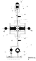
- Components 4 to 8 in FIG. 1 represent the actuator previously referred to as actuator 1.
- the liquid is fed to actuator 1 through a line 17.
- a pressure or mass flow change is impressed on the liquid by, in this case, two pistons 6.
- the necessary separation and sealing between the liquid and the drive element is ensured by the piston 6.
- the pistons 6 are in turn driven by two drive elements 7, which can be either electrostrictive or magnetostrictive components.
- the deflection or length of the drive elements 7 is controlled by the control signal 14.
- the drive elements 7 are supported on the pistons 6 on the housing covers 5 for the application of force.
- the necessary restoring force for the piston 6 is applied by the liquid pressure.
- the pistons 6 have the task of increasing or decreasing the mass flow modulation by enlarging or reducing their end face in comparison to the end faces of the drive elements 7.
- the use of two or more pistons 6 and drive elements 7 is not necessary, but the power of the actuator 1 can be increased with the number of pistons 6 and drive elements 7. In the same sense, of course, several actuators 1 can also be placed in the liquid line. In the case of a plurality of pistons 6 and drive elements 7, the correct actuation 14 must be ensured, the change in length of the drive elements 7 must take place in the same way (positive expansion or negative expansion).
- the shape of the piston 6, the cylinder in the actuator housing 4 and the drive element 7 should preferably be cylindrical.
- the shape of the piston face which faces the liquid, can have different geometries. Fastening the drive elements 7 to the actuator end cover 5 and to the piston 6 is not necessary since the drive element 7 only has to transmit compressive forces.
- the drive element is centered by a suitable fit in the piston 6 and in the actuator cover 5, guided and protected against tilting of the drive elements 7 relative to the piston 6 and actuator housing cover 5.
- the actuator housing 4, the actuator end caps 5 and the pistons 6 are to be made as stiff as possible in order to minimize possible deformations due to the high actuating forces of the drive elements 7 or pressures of the liquids on the pistons 6 and the actuator housing 4, since otherwise the effectively usable actuating path of the drive elements 7 would be reduced.
- connection between the actuator housing 4 and the actuator cover 5 can also be carried out as stiffly as possible using the known methods, such as screws, rivets, soldering, welding, etc.
- the liquid delivery lines 17 and 18 are also to be made as rigid as possible, for example copper or steel pipes, no plastic - or rubber hoses.
- the connection of the liquid delivery lines 17 and 18 are to be attached to the actuator housing 4 using known methods, such as cutting ring fittings, pipe threads, soldering, welding, etc.
- the sealing between the piston 6 and its guide or the cylinder in the actuator housing 4 is accomplished by means of known sealing methods, for example O-ring 8.
- the travel of the drive element 7 can be monitored by means of a strain gauge (DMS) attached to it and is referred to below as a monitoring signal.
- the monitoring signal from the strain gauge can serve as an input signal for a controller 31 or 39.
- the monitoring and control signal lines 14 for the drive element 7 can be carried out through the actuator housing 4 or through the actuator cover 5 or between the two and need not necessarily be sealed. Easier assembly and disassembly is achieved if the monitoring and control signal lines 14 are carried out between the actuator housing 4 and the actuator cover 5, for example in a groove.
- actuator 1 Power loss can cause the drive elements 7 to heat up, which can impair their service life. For this reason it is possible to cool the drive elements by flushing them with a suitable medium, eg air.
- the cooling medium can be supplied and removed in a suitable manner through openings, for example bores, in the actuator housing 4 and / or actuator cover 5.
- the integration of actuator 1 into the conveyor system is explained in Figure 2 as an example.
- the nozzle head 2 can be mounted directly on the actuator housing 4 or separated from it by a line 18.
- Other components integrated in the conveyor system such as. B. mass flow control, check and pressure relief valves are not a hindrance to the operation of the actuator 1, but may influence the usable frequency range.
- the liquid is to be conveyed free of gas or air as far as possible.
- the construction of the entire conveyor system is to be carried out in such a way that gas or air bubbles contained in the system are automatically discharged through the nozzle during commissioning. If this is not guaranteed, venting options must be provided at critical points in the conveyor system.
- pressure transducer means 15, 16 can be inserted into the delivery line 17, 18. The pressure sensor 15 serves to measure the quality of the pressure modulation to be achieved and thus indirectly provides a measure of the mass flow modulation.
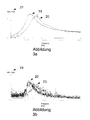
- the transfer functions 19 and 20 of the injection pressure 30 based on the unamplified actuator control signal 14 are plotted for two different pipe lengths 17, with diesel fuel being used as the liquid.
- the method of stimulating the pipeline resonance can be used to specifically improve the transmission behavior in a specific frequency range.
- the pipeline resonance can be influenced by the arrangement of the various elements of the delivery system as well as the lengths of the liquid delivery lines 17 and 18 and various internals such as check valve, mass flow control valve, etc.
- the higher order can also be used.
- An expansion or change in the transmission behavior (injection pressure 30 based on unamplified actuator control signal 14) during operation, in the sense of the method just described, is possible, for example, by variable lengths of the liquid delivery lines 17 and 18 that can be adjusted during operation.
- the effect of the excitation on the flame was recorded in the frequency response representation in Figure 3b according to Figure 3a.
- the temporal power release of the combustion was measured with a photomultiplier 36 using the radiation from the OH radical. It can be seen from the course that the actuator 1 has considerable potential for influencing the combustion and thus for actively suppressing combustion vibrations.
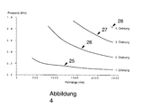
- FIG. 4 shows the course of the frequency maxima of the transmission behavior of the injection pressure 30 based on the unamplified actuator control signal 14 first order 25, second order 26, third order 27 and fourth order 28 over the length of the liquid delivery line 17. Due to the acoustic resonance condition of pipelines, hyperbolas are obtained here. Because of the final condition on the conveying device 3 and the nozzle 2, which has not yet been determined in detail, precise modeling (description by means of a waveform) has so far not been possible.
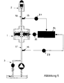
- Pressure and mass flow fluctuations that are generated by conveying or metering devices can be compensated for by an arrangement according to Figure 5 .
- the pressure fluctuations generated by the conveying or metering devices are measured by a pressure converter means 16 and fed to a controller 31 as an input signal 29. From this, the controller 31 generates an actuator control signal 14, which must be designed in such a way that the pressure fluctuations in the delivery system are canceled out by destructive interference with the pressure fluctuations generated by the actuator 1.
- the controller can consist, for example, of a filter, phase shifter and amplifier or of an adaptive filter etc.
- the quality of the extinction of the pressure fluctuations in the conveyor system can be measured with the pressure converter means 15. This signal can be used as a controller input signal 30 to optimize the control behavior of the controller 31.
- Figure 6 shows a possible structure for actively suppressing combustion vibrations with the actuator 1 according to the invention.
- the nozzle head 2 and the pressure transducer means 15 are attached directly to the actuator 1.
- the control system 39 - which can either consist of an adaptive filter, a phase shifter with amplifier or the like - is supplied with the sound pressure 37 and / or the combustion power 38 as an input variable. Correction of the actuator control signal 14 with regard to deviations which can be attributed to the transmission behavior of the actuator is possible by introducing the injection pressure signal 30 into the regulator system.
- the injection pressure is measured by means of a pressure converter means 15 in the actuator housing 4 or shortly before the nozzle head 2.
- the controller 39 determines an actuating signal 14 which is fed to the actuator 1 for suppressing the combustion oscillation.
- the task of the control system 39 is to actuate the actuator 1 in such a way that the combustion oscillation is suppressed by countercyclical fuel supply, based on the fluctuation in the performance of the combustion or on the sound pressure oscillation in the combustion chamber.
- fuel pressure fluctuations that would otherwise lead to externally excited combustion vibrations can also be compensated for in the delivery system.
- An exemplary embodiment for the regulation of these fuel pressure fluctuations is given in Figure 5.
- Figure 6 shows that the active suppression of self-excited combustion vibrations and the regulation of fuel pressure fluctuations is possible with a combined regulator system 39.
- the control system 39 consisted of a filter for suppressing noise, an analog phase shifter for phase shifting the input signal and an amplifier for controlling the actuator 1.
- the power fluctuation 38 of the combustion was fed to this control system 39 as an input signal, here phase-shifted and amplified and then the actuator 1 supplied as control signal 14.
- the phase shift was chosen so that countercyclical fuel injection - related to the vibration of the combustion in the combustion chamber - suppressed the combustion vibration.
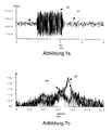
- combustion chamber pressure signal 37 was recorded with active suppression 41 and without active suppression 40 and plotted in Figure 7a .
Landscapes
- Engineering & Computer Science (AREA)
- Chemical & Material Sciences (AREA)
- Combustion & Propulsion (AREA)
- Mechanical Engineering (AREA)
- General Engineering & Computer Science (AREA)
- Special Spraying Apparatus (AREA)
- Fuel-Injection Apparatus (AREA)
- Reciprocating Pumps (AREA)
Claims (14)
- Dispositif d'actionnement (1) destiné à être interposé entre une buse (2, 10) et un dispositif d'alimentation (3), comprenant un élément d'actionnement servant à moduler le courant de masse d'un liquide s'écoulant du dispositif d'alimentation (3) vers la buse (2, 10),
caractérisé en ce que l'élément d'actionnement est formé par un dispositif pourvu d'au moins un élément électrostrictif ou magnétostrictif (7), un piston (6) servant à transmettre au liquide une force de réglage produite par l'élément (7) étant associé à l'élément (7). - Dispositif d'actionnement (1) selon la revendication 1, dans lequel le piston (6) a une surface frontale pouvant être soumise à l'action du liquide et l'élément (7) a une surface frontale touchant le piston (6), la surface frontale du piston (6) pouvant être soumise à l'action du liquide étant plus grande que la surface frontale de l'élément (7) touchant le piston (6).
- Dispositif d'actionnement (1) selon l'une des revendications 1 ou 2, dans lequel l'élément d'actionnement comprend plusieurs éléments électrostrictifs ou magnétostrictifs (7), un piston correspondant (6) étant à associé, respectivement, à chaque élément.
- Système dans une installation pour l'alimentation d'un liquide d'un dispositif d'alimentation (3) vers une buse (2, 10), lequel système comprend une conduite d'alimentation (17) insérée entre le dispositif d'alimentation (3) et la buse (2, 10) ainsi qu'un dispositif d'actionnement (1) interposé dans cette conduite et comprenant un élément d'actionnement (7) servant à moduler le courant de masse du liquide, caractérisé en ce que l'élément d'actionnement comprend au moins un élément électrostrictif ou magnétostrictif (7) auquel est associé un piston (6) servant à transmettre au liquide une force de réglage produite par l'élément (7), en ce que l'on prévoit un régulateur (31) servant à fournir un signal de commande (14) pour le dispositif d'actionnement (1) ainsi qu'un moyen de convertisseur de pression (16) situé entre le dispositif d'actionnement (1) et une pompe (12) dans le dispositif d'alimentation (3) et servant à fournir un signal d'entrée (29) pour le régulateur (31), et en ce que le régulateur (31) est adapté pour compenser les fluctuations d'un courant de masse du liquide - lesquelles fluctuations sont causées par la pompe (12) et parviennent au régulateur (31) avec le signal d'entrée (29) - au moyen du signal de sortie (14) amené au dispositif d'actionnement (1).
- Système selon la revendication 4, dans lequel on prévoit un autre moyen de convertisseur de pression (15) inséré dans la conduite d'alimentation (17) en aval du dispositif d'actionnement (1) et servant à fournir un autre signal d'entrée (30) pour le régulateur (31), le régulateur (31) étant adapté pour compenser les fluctuations en fonction, en plus, de l'autre signal d'entrée (30).
- Système selon l'une des revendications 4 ou 5, dans lequel la pompe (12) est réglée pour refouler le liquide à une certaine vitesse de rotation, et dans lequel le régulateur (31) est adapté pour compenser les fluctuations en fonction, en plus, de la vitesse de rotation.
- Système dans une installation pour l'alimentation d'un liquide d'un dispositif d'alimentation (3) vers une buse (2, 19) au niveau d'un système de combustion (34), lequel système comprend une conduite d'alimentation (17) ainsi qu'un dispositif d'actionnement (1) interposé dans cette conduite et servant à moduler le courant de masse du liquide au moyen d'un élément d'actionnement (7), caractérisé en ce que l'élément d'actionnement comprend au moins un élément électrostrictif ou magnétostrictif (7) auquel est associé un piston (6) servant à transmettre au liquide une force de réglage produite par l'élément (7), la buse (2, 10) étant prévue pour alimenter le liquide dans le système de combustion (34), en ce qu'un convertisseur de pression (35) destiné à produire un signal de pression (37) et/ou un convertisseur optique (36) destiné à produire un signal de puissance (38) est resp. sont relié/s au système de combustion (34), et en ce qu'on prévoit un régulateur (39) pour produire un signal de commande (14) pour le dispositif d'actionnement (1) en fonction du signal de pression (37) et/ou du signal de puissance (39).
- Système selon la revendication 7, dans lequel un autre convertisseur de pression (15) est prévu dans la conduite d'alimentation (17) en aval du dispositif d'actionnement (1) pour produire un autre signal de pression (30) et le régulateur (39) est adapté pour produire le signal de commande (14) en fonction, en plus, du signal de pression supplémentaire (30), afin de tenir compte du comportement de transfert du dispositif d'actionnement (1).
- Système selon l'une des revendications 7 ou 8, dans lequel le système de combustion (34) est une chambre de combustion (34) d'une turbine à gaz.
- Système selon l'une des revendications 4 à 9, dans lequel la conduite d'alimentation (17) a une fréquence de résonance accordée de manière ciblée dans une gamme de fréquences déterminée pour améliorer le comportement de transfert du dispositif d'actionnement (1).
- Utilisation du dispositif d'actionnement (1) selon l'une des revendications 1 à 3 dans un système dans lequel un liquide sous pression est alimenté d'un dispositif d'alimentation (3) vers une buse (2, 10) à travers une conduite d'alimentation (17), le dispositif d'actionnement (1) étant interposé dans la conduite d'alimentation (17) et étant prévu pour imposer au liquide une modulation du courant de masse et pour de ce fait, pulvériser le liquide finement ou le transformer en un jet vif pulsé sortant de la buse (2, 10) à force impulsive élevée.
- Utilisation selon la revendication 11, le liquide étant un combustible liquide et étant injecté dans une chambre de combustion (34) en vue de la combustion du combustible.
- Utilisation selon la revendication 12, la combustion se déroulant par pulsation en raison de la modulation du courant de masse.
- Utilisation selon l'une des revendications 12 ou 13, les pulsations survenant dans la combustion étant amorties par la modulation du courant de masse.
Applications Claiming Priority (2)
| Application Number | Priority Date | Filing Date | Title |
|---|---|---|---|
| DE4241729A DE4241729A1 (de) | 1992-12-10 | 1992-12-10 | Aktuator zum Aufprägen von Massenstrom- bzw. Druckschwankungen auf unter Druck stehende Flüssigkeitsströme |
| DE4241729 | 1992-12-10 |
Publications (2)
| Publication Number | Publication Date |
|---|---|
| EP0601608A1 EP0601608A1 (fr) | 1994-06-15 |
| EP0601608B1 true EP0601608B1 (fr) | 1998-06-03 |
Family
ID=6474960
Family Applications (1)
| Application Number | Title | Priority Date | Filing Date |
|---|---|---|---|
| EP93120001A Expired - Lifetime EP0601608B1 (fr) | 1992-12-10 | 1993-12-10 | Dispositif d'actionnement pour imposer des fluctuations des courants de masse ou des pressions dans un courant de liquide sous pression |
Country Status (3)
| Country | Link |
|---|---|
| EP (1) | EP0601608B1 (fr) |
| DE (2) | DE4241729A1 (fr) |
| ES (1) | ES2117086T3 (fr) |
Families Citing this family (22)
| Publication number | Priority date | Publication date | Assignee | Title |
|---|---|---|---|---|
| FR2726603B1 (fr) * | 1994-11-09 | 1996-12-13 | Snecma | Dispositif de controle actif des instabilites de combustion et de decokefaction d'un injecteur de carburant |
| DE19504610C2 (de) * | 1995-02-13 | 2003-06-18 | Alstom | Vorrichtung zur Dämpfung thermoakustischer Druckschwingungen |
| DE19542918A1 (de) * | 1995-11-17 | 1997-05-22 | Asea Brown Boveri | Vorrichtung zur Dämpfung thermoakustischer Druckschwingungen |
| DE19636093B4 (de) * | 1996-09-05 | 2004-07-29 | Siemens Ag | Verfahren und Vorrichtung zur akustischen Modulation einer von einem Hybridbrenner erzeugten Flamme |
| RU2186298C2 (ru) * | 1996-09-16 | 2002-07-27 | Сименс Акциенгезелльшафт | Способ и устройство для сжигания топлива с воздухом |
| DE19640980B4 (de) * | 1996-10-04 | 2008-06-19 | Alstom | Vorrichtung zur Dämpfung von thermoakustischen Schwingungen in einer Brennkammer |
| DE19841329C2 (de) * | 1998-09-10 | 2003-04-17 | Daimler Chrysler Ag | Einspritzanlage für einen Verbrennungsmotor und Betriebsverfahren hierfür |
| DE19934612A1 (de) | 1999-07-23 | 2001-01-25 | Abb Alstom Power Ch Ag | Verfahren zur aktiven Unterdrückung von strömungsmechanischen Instabilitäten in einem Verbrennungssystem sowie Verbrennungssystem zur Durchführung des Verfahrens |
| DE10040868A1 (de) * | 2000-08-21 | 2002-03-07 | Alstom Power Nv | Verfahren zur Reduzierung thermoakustischer Schwingungen in Strömungskraftmaschinen mit einem Brennersystem |
| DE10148603B4 (de) * | 2001-10-02 | 2004-02-19 | Siemens Ag | Aktoreinheit mit wenigstens zwei Aktorelementen |
| DE102006051375A1 (de) * | 2006-10-27 | 2008-04-30 | Rolls-Royce Deutschland Ltd & Co Kg | Aerodynamische Verkleidung für im Nebenstromkanal eines Gasturbinentriebwerks angeordnete Einbauten |
| DE102006053278A1 (de) * | 2006-11-03 | 2008-05-08 | Deutsches Zentrum für Luft- und Raumfahrt e.V. | Brennkammervorrichtung |
| EP1942303A1 (fr) * | 2007-01-02 | 2008-07-09 | Siemens Aktiengesellschaft | Brûleur pour turbine à gaz et procédé de contrôle de carburant pour alimenter un brûleur |
| RU2426945C2 (ru) * | 2007-01-02 | 2011-08-20 | Сименс Акциенгезелльшафт | Горелка и устройство топливоподачи для газовой турбины |
| CN104184366B (zh) * | 2014-07-21 | 2016-03-23 | 浙江大学 | 双向磁致伸缩式宽频振动能量采集器 |
| DE102016225400B4 (de) * | 2016-12-19 | 2022-12-29 | Robert Bosch Gmbh | Dämpfungssystem in einem Hochdruck-Kraftstoffeinspritzsystem |
| CN108870439A (zh) * | 2018-07-27 | 2018-11-23 | 中国东方电气集团有限公司 | 一种用于燃烧设备的燃烧振荡控制结构 |
| GB201818268D0 (en) * | 2018-11-09 | 2018-12-26 | Rolls Royce | Shaft resonance control |
| DE102019204422A1 (de) * | 2019-03-29 | 2020-10-01 | Siemens Aktiengesellschaft | Vorhersage einer Verbrennungsdynamik einer Gasturbine |
| DE102020101799B4 (de) | 2020-01-27 | 2025-07-03 | Dr. Ing. H.C. F. Porsche Aktiengesellschaft | Vorrichtung und Verfahren zum Betreiben eines Kraftstoffbrenners |
| CN112128989A (zh) * | 2020-08-31 | 2020-12-25 | 华帝股份有限公司 | 一种热水器噪音自适应的控制方法及热水器 |
| CN115193611B (zh) * | 2022-09-02 | 2023-07-25 | 江西奥普照明有限公司 | 一种led自动化喷涂生产线 |
Family Cites Families (4)
| Publication number | Priority date | Publication date | Assignee | Title |
|---|---|---|---|---|
| US3896889A (en) * | 1971-08-31 | 1975-07-29 | Hydroacoustic Inc | Hydroacoustic apparatus |
| GB1500908A (en) * | 1974-06-05 | 1978-02-15 | Ici Ltd | Process for production of drop streams |
| DE3521674A1 (de) * | 1985-06-18 | 1986-12-18 | Vadim Netanya Spolanski | Verfahren und vorrichtung fuer einen hydraulischen und/oder hydromechanischen kraftantrieb mittels impulserregten hohen und hoechsten drucken, mit nach frequenzperioden des erregten druckes und nach dessen groesse regelbarer druckvervielfachung |
| GB2239961A (en) * | 1990-01-02 | 1991-07-17 | Gen Electric | Control of combustion-induced instabilities |
-
1992
- 1992-12-10 DE DE4241729A patent/DE4241729A1/de not_active Withdrawn
-
1993
- 1993-12-10 DE DE59308642T patent/DE59308642D1/de not_active Expired - Lifetime
- 1993-12-10 EP EP93120001A patent/EP0601608B1/fr not_active Expired - Lifetime
- 1993-12-10 ES ES93120001T patent/ES2117086T3/es not_active Expired - Lifetime
Also Published As
| Publication number | Publication date |
|---|---|
| DE59308642D1 (de) | 1998-07-09 |
| EP0601608A1 (fr) | 1994-06-15 |
| DE4241729A1 (de) | 1994-06-16 |
| ES2117086T3 (es) | 1998-08-01 |
Similar Documents
| Publication | Publication Date | Title |
|---|---|---|
| EP0601608A1 (fr) | Dispositif d'actionnement pour imposer des fluctuations des courants de masse ou des pressions dans un courant de liquide sous pression | |
| DE69508344T2 (de) | Aktive Regeleinrichtung der Verbrennungsinstabilität und der Entkohlung eines Brennstoffeinspritzventils | |
| EP0925472B1 (fr) | Procede pour la suppression des oscillations de combustion et dispositif pour la combustion d'un combustible avec de l'air | |
| EP1004823B1 (fr) | Dispositif d'amortissement pour la réduction de l'amplitude d'oscillation d'ondes acoustiques pour un brûleur | |
| EP0925473B1 (fr) | Procede et dispositif pour la modulation acoustique d'une flamme produite par un bruleur hybride | |
| DE102009012914A1 (de) | Aktive Musterfaktorsteuerung/regelung für Gasturbinenmotoren | |
| EP0611434A1 (fr) | Dispositif permettant de supprimer les vibrations dues a la combustion dans une chambre de combustion d'une installation a turbine a gaz | |
| DE10040869A1 (de) | Verfahren und Vorrichtung zur Unterdrückung von Strömungswirbeln innerhalb einer Strömungskraftmaschine | |
| CH703661A2 (de) | Flammrohrdeckelbaugruppe mit Stützstäben zum Einstellen der Frequenz von einer freitragenden Kraftstoffdüse. | |
| EP0974788B1 (fr) | Dispositif d'atténuation adaptée de bruit dans une turbomachine | |
| DE10213682A1 (de) | Verfahren und Vorrichtung zur Kontrolle von thermoakustischen Instabilitäten bzw. Schwingungen in einem Verbrennungssystem | |
| EP3168533B1 (fr) | Irrorateur à liquides | |
| DE4040745A1 (de) | Aktive regelung von durch verbrennung hervorgerufene instabilitaeten | |
| DE4336096A1 (de) | Vorrichtung zur Reduktion von Schwingungen in Brennkammern | |
| EP1382838B1 (fr) | Injecteur de carburant | |
| EP1182399A2 (fr) | Procédé pour la réduction des oscillations thermoacoustiques dans une turbomachine en utilisant le dispositif de combustion | |
| DE3937917A1 (de) | Verfahren zum intermittierenden einspritzen von brennstoff in den brennraum einer brennkraftmaschine, sowie vorrichtung zur durchfuehrung dieses verfahrens | |
| EP1114967B1 (fr) | Procédé et dispositif pour supprimer les tourbillons dans une chambre à combustion d'une turbomachine | |
| DE10013451B4 (de) | Vorrichtung zur Erzeugung monodisperser Tropfen | |
| WO2011067370A1 (fr) | Dispositif de refoulement servant à refouler un agent réducteur | |
| DE102018211650A1 (de) | Vorrichtung zur Herstellung von Partikeln | |
| DE69402627T2 (de) | Tintenstrahltröpchengenerator | |
| DE60104210T2 (de) | Kraftstoffeinspritzvorrichtung für eine brennkraftmaschine | |
| EP1429004A2 (fr) | Méthode et dispositif influençant les oscillations thermoacoustiques dans les systèmes de combustion | |
| AT516424B1 (de) | Vorrichtung und Verfahren zum Betreiben einer Flamme |
Legal Events
| Date | Code | Title | Description |
|---|---|---|---|
| PUAI | Public reference made under article 153(3) epc to a published international application that has entered the european phase |
Free format text: ORIGINAL CODE: 0009012 |
|
| AK | Designated contracting states |
Kind code of ref document: A1 Designated state(s): CH DE ES FR GB IT LI SE |
|
| 17P | Request for examination filed |
Effective date: 19941205 |
|
| 17Q | First examination report despatched |
Effective date: 19960202 |
|
| RAP1 | Party data changed (applicant data changed or rights of an application transferred) |
Owner name: SIEMENS AKTIENGESELLSCHAFT |
|
| GRAG | Despatch of communication of intention to grant |
Free format text: ORIGINAL CODE: EPIDOS AGRA |
|
| GRAG | Despatch of communication of intention to grant |
Free format text: ORIGINAL CODE: EPIDOS AGRA |
|
| GRAH | Despatch of communication of intention to grant a patent |
Free format text: ORIGINAL CODE: EPIDOS IGRA |
|
| GRAH | Despatch of communication of intention to grant a patent |
Free format text: ORIGINAL CODE: EPIDOS IGRA |
|
| GRAA | (expected) grant |
Free format text: ORIGINAL CODE: 0009210 |
|
| AK | Designated contracting states |
Kind code of ref document: B1 Designated state(s): CH DE ES FR GB IT LI SE |
|
| REG | Reference to a national code |
Ref country code: CH Ref legal event code: NV Representative=s name: SIEMENS SCHWEIZ AG Ref country code: CH Ref legal event code: EP |
|
| REF | Corresponds to: |
Ref document number: 59308642 Country of ref document: DE Date of ref document: 19980709 |
|
| REG | Reference to a national code |
Ref country code: ES Ref legal event code: FG2A Ref document number: 2117086 Country of ref document: ES Kind code of ref document: T3 |
|
| ITF | It: translation for a ep patent filed | ||
| GBT | Gb: translation of ep patent filed (gb section 77(6)(a)/1977) |
Effective date: 19980827 |
|
| ET | Fr: translation filed | ||
| PLBE | No opposition filed within time limit |
Free format text: ORIGINAL CODE: 0009261 |
|
| STAA | Information on the status of an ep patent application or granted ep patent |
Free format text: STATUS: NO OPPOSITION FILED WITHIN TIME LIMIT |
|
| 26N | No opposition filed | ||
| REG | Reference to a national code |
Ref country code: GB Ref legal event code: IF02 |
|
| REG | Reference to a national code |
Ref country code: CH Ref legal event code: PCAR Free format text: SIEMENS SCHWEIZ AG;INTELLECTUAL PROPERTY FREILAGERSTRASSE 40;8047 ZUERICH (CH) |
|
| PGFP | Annual fee paid to national office [announced via postgrant information from national office to epo] |
Ref country code: IT Payment date: 20121221 Year of fee payment: 20 Ref country code: SE Payment date: 20121210 Year of fee payment: 20 Ref country code: GB Payment date: 20121212 Year of fee payment: 20 |
|
| PGFP | Annual fee paid to national office [announced via postgrant information from national office to epo] |
Ref country code: CH Payment date: 20130312 Year of fee payment: 20 Ref country code: DE Payment date: 20130218 Year of fee payment: 20 Ref country code: ES Payment date: 20130114 Year of fee payment: 20 Ref country code: FR Payment date: 20130131 Year of fee payment: 20 |
|
| REG | Reference to a national code |
Ref country code: DE Ref legal event code: R071 Ref document number: 59308642 Country of ref document: DE |
|
| REG | Reference to a national code |
Ref country code: DE Ref legal event code: R071 Ref document number: 59308642 Country of ref document: DE |
|
| REG | Reference to a national code |
Ref country code: CH Ref legal event code: PL |
|
| REG | Reference to a national code |
Ref country code: GB Ref legal event code: PE20 Expiry date: 20131209 |
|
| PG25 | Lapsed in a contracting state [announced via postgrant information from national office to epo] |
Ref country code: DE Free format text: LAPSE BECAUSE OF EXPIRATION OF PROTECTION Effective date: 20131211 Ref country code: GB Free format text: LAPSE BECAUSE OF EXPIRATION OF PROTECTION Effective date: 20131209 |
|
| REG | Reference to a national code |
Ref country code: SE Ref legal event code: EUG |
|
| REG | Reference to a national code |
Ref country code: ES Ref legal event code: FD2A Effective date: 20140925 |
|
| PG25 | Lapsed in a contracting state [announced via postgrant information from national office to epo] |
Ref country code: ES Free format text: LAPSE BECAUSE OF EXPIRATION OF PROTECTION Effective date: 20131211 |