EP0601645A1 - Getriebeschaltung ohne Unterbrechung des Antriebs mit sich überschneidenden Gangbereichen - Google Patents
Getriebeschaltung ohne Unterbrechung des Antriebs mit sich überschneidenden Gangbereichen Download PDFInfo
- Publication number
- EP0601645A1 EP0601645A1 EP93203388A EP93203388A EP0601645A1 EP 0601645 A1 EP0601645 A1 EP 0601645A1 EP 93203388 A EP93203388 A EP 93203388A EP 93203388 A EP93203388 A EP 93203388A EP 0601645 A1 EP0601645 A1 EP 0601645A1
- Authority
- EP
- European Patent Office
- Prior art keywords
- ratios
- range
- clutches
- clutch
- gear
- Prior art date
- Legal status (The legal status is an assumption and is not a legal conclusion. Google has not performed a legal analysis and makes no representation as to the accuracy of the status listed.)
- Granted
Links
Images

Classifications
-
- F—MECHANICAL ENGINEERING; LIGHTING; HEATING; WEAPONS; BLASTING
- F16—ENGINEERING ELEMENTS AND UNITS; GENERAL MEASURES FOR PRODUCING AND MAINTAINING EFFECTIVE FUNCTIONING OF MACHINES OR INSTALLATIONS; THERMAL INSULATION IN GENERAL
- F16H—GEARING
- F16H37/00—Combinations of mechanical gearings, not provided for in groups F16H1/00 - F16H35/00
- F16H37/02—Combinations of mechanical gearings, not provided for in groups F16H1/00 - F16H35/00 comprising essentially only toothed or friction gearings
- F16H37/04—Combinations of toothed gearings only
- F16H37/042—Combinations of toothed gearings only change gear transmissions in group arrangement
- F16H37/043—Combinations of toothed gearings only change gear transmissions in group arrangement without gears having orbital motion
-
- F—MECHANICAL ENGINEERING; LIGHTING; HEATING; WEAPONS; BLASTING
- F16—ENGINEERING ELEMENTS AND UNITS; GENERAL MEASURES FOR PRODUCING AND MAINTAINING EFFECTIVE FUNCTIONING OF MACHINES OR INSTALLATIONS; THERMAL INSULATION IN GENERAL
- F16H—GEARING
- F16H61/00—Control functions within control units of change-speed- or reversing-gearings for conveying rotary motion ; Control of exclusively fluid gearing, friction gearing, gearings with endless flexible members or other particular types of gearing
- F16H61/70—Control functions within control units of change-speed- or reversing-gearings for conveying rotary motion ; Control of exclusively fluid gearing, friction gearing, gearings with endless flexible members or other particular types of gearing specially adapted for change-speed gearing in group arrangement, i.e. with separate change-speed gear trains arranged in series, e.g. range or overdrive-type gearing arrangements
- F16H61/702—Control functions within control units of change-speed- or reversing-gearings for conveying rotary motion ; Control of exclusively fluid gearing, friction gearing, gearings with endless flexible members or other particular types of gearing specially adapted for change-speed gearing in group arrangement, i.e. with separate change-speed gear trains arranged in series, e.g. range or overdrive-type gearing arrangements using electric or electrohydraulic control means
-
- F—MECHANICAL ENGINEERING; LIGHTING; HEATING; WEAPONS; BLASTING
- F16—ENGINEERING ELEMENTS AND UNITS; GENERAL MEASURES FOR PRODUCING AND MAINTAINING EFFECTIVE FUNCTIONING OF MACHINES OR INSTALLATIONS; THERMAL INSULATION IN GENERAL
- F16H—GEARING
- F16H2300/00—Determining of new ratio
- F16H2300/18—Determining the range
-
- F—MECHANICAL ENGINEERING; LIGHTING; HEATING; WEAPONS; BLASTING
- F16—ENGINEERING ELEMENTS AND UNITS; GENERAL MEASURES FOR PRODUCING AND MAINTAINING EFFECTIVE FUNCTIONING OF MACHINES OR INSTALLATIONS; THERMAL INSULATION IN GENERAL
- F16H—GEARING
- F16H61/00—Control functions within control units of change-speed- or reversing-gearings for conveying rotary motion ; Control of exclusively fluid gearing, friction gearing, gearings with endless flexible members or other particular types of gearing
- F16H61/02—Control functions within control units of change-speed- or reversing-gearings for conveying rotary motion ; Control of exclusively fluid gearing, friction gearing, gearings with endless flexible members or other particular types of gearing characterised by the signals used
- F16H61/0202—Control functions within control units of change-speed- or reversing-gearings for conveying rotary motion ; Control of exclusively fluid gearing, friction gearing, gearings with endless flexible members or other particular types of gearing characterised by the signals used the signals being electric
- F16H61/0248—Control units where shifting is directly initiated by the driver, e.g. semi-automatic transmissions
-
- F—MECHANICAL ENGINEERING; LIGHTING; HEATING; WEAPONS; BLASTING
- F16—ENGINEERING ELEMENTS AND UNITS; GENERAL MEASURES FOR PRODUCING AND MAINTAINING EFFECTIVE FUNCTIONING OF MACHINES OR INSTALLATIONS; THERMAL INSULATION IN GENERAL
- F16H—GEARING
- F16H61/00—Control functions within control units of change-speed- or reversing-gearings for conveying rotary motion ; Control of exclusively fluid gearing, friction gearing, gearings with endless flexible members or other particular types of gearing
- F16H61/16—Inhibiting or initiating shift during unfavourable conditions , e.g. preventing forward-reverse shift at high vehicle speed, preventing engine overspeed
-
- F—MECHANICAL ENGINEERING; LIGHTING; HEATING; WEAPONS; BLASTING
- F16—ENGINEERING ELEMENTS AND UNITS; GENERAL MEASURES FOR PRODUCING AND MAINTAINING EFFECTIVE FUNCTIONING OF MACHINES OR INSTALLATIONS; THERMAL INSULATION IN GENERAL
- F16H—GEARING
- F16H61/00—Control functions within control units of change-speed- or reversing-gearings for conveying rotary motion ; Control of exclusively fluid gearing, friction gearing, gearings with endless flexible members or other particular types of gearing
- F16H61/68—Control functions within control units of change-speed- or reversing-gearings for conveying rotary motion ; Control of exclusively fluid gearing, friction gearing, gearings with endless flexible members or other particular types of gearing specially adapted for stepped gearings
- F16H61/684—Control functions within control units of change-speed- or reversing-gearings for conveying rotary motion ; Control of exclusively fluid gearing, friction gearing, gearings with endless flexible members or other particular types of gearing specially adapted for stepped gearings without interruption of drive
-
- F—MECHANICAL ENGINEERING; LIGHTING; HEATING; WEAPONS; BLASTING
- F16—ENGINEERING ELEMENTS AND UNITS; GENERAL MEASURES FOR PRODUCING AND MAINTAINING EFFECTIVE FUNCTIONING OF MACHINES OR INSTALLATIONS; THERMAL INSULATION IN GENERAL
- F16H—GEARING
- F16H61/00—Control functions within control units of change-speed- or reversing-gearings for conveying rotary motion ; Control of exclusively fluid gearing, friction gearing, gearings with endless flexible members or other particular types of gearing
- F16H61/70—Control functions within control units of change-speed- or reversing-gearings for conveying rotary motion ; Control of exclusively fluid gearing, friction gearing, gearings with endless flexible members or other particular types of gearing specially adapted for change-speed gearing in group arrangement, i.e. with separate change-speed gear trains arranged in series, e.g. range or overdrive-type gearing arrangements
-
- Y—GENERAL TAGGING OF NEW TECHNOLOGICAL DEVELOPMENTS; GENERAL TAGGING OF CROSS-SECTIONAL TECHNOLOGIES SPANNING OVER SEVERAL SECTIONS OF THE IPC; TECHNICAL SUBJECTS COVERED BY FORMER USPC CROSS-REFERENCE ART COLLECTIONS [XRACs] AND DIGESTS
- Y10—TECHNICAL SUBJECTS COVERED BY FORMER USPC
- Y10T—TECHNICAL SUBJECTS COVERED BY FORMER US CLASSIFICATION
- Y10T74/00—Machine element or mechanism
- Y10T74/19—Gearing
- Y10T74/19219—Interchangeably locked
- Y10T74/19251—Control mechanism
Definitions
- the present invention relates to powershift transmissions having large numbers of powershift gear ratios, and more particularly to a method and apparatus for providing smoother shifts when plural simultaneous clutch changes are required.
- US-A-5.012.690 discloses a powershift transmission for a tractor, the transmission having 18 forward and 9 reverse gear ratios.
- the transmission has a 3-ratio input clutch section, a 3-ratio center clutch section and a 2-forward, 1-reverse ratio output clutch section.
- the combination of 3x3x2 gives 18 forward ratios.
- the arrangement requires multiple clutch swaps to accomplish certain shifts and this in turn requires that internal transmission components must change speed considerably.
- the 10th forward ratio is achieved by engaging the slowest ratio in both the input and center clutch sections and engaging the fast forward ratio in the output clutch section.
- both the input and center sections must shift to their fastest ratios while the output section shifts to the slow forward ratio.
- 3 clutches must engage, 3 other clutches must disengage, and many gears, shafts and clutches in the transmission must speed up thereby absorbing considerable energy.
- Driving torque through the transmission cannot be maintained throughout the shift thus resulting in a shift that is not as smooth as other gear shifts if the tractor is under load.
- the present invention is based on the observation that during most heavy load operations most of the shifting takes place between two or three ratios.
- the transmission described in the above-referenced patent has the shift sequence 1L 2L 3L 4L 5L 6L 7L 8L 9L 1H 2H 3H 4H 5H 6H 7H 8H 9H where 9L and 1H correspond to the 9th and 10th forward ratios mentioned above.
- the number of range shifts may be materially reduced by adopting the shift sequences Upshift ....7L 8L 9L 3H... Downshift ....3H 2H 1H 7L...
- a powershift transmission having a rotatable input shaft, a rotatable output shaft, a plurality of clutch sections each including a plurality of clutches and gears, said clutches being energizable to selectively connect said input shaft in driving relationship with said output shaft at one of a plurality of gear ratios, said plurality of clutches of one of said clutch sections including first and second clutches which, when energized, limit the gear ratio to a lower range or a higher range, respectively.
- the transmission is characterized in that said lower and higher ranges of ratios overlap, with the two lowest gear ratios in said high range being substantially equal to the two highest gear ratios of said low range.
- a method is provided of shifting a powershift transmission having a rotatable input shaft, a rotatable output shaft, a plurality of gears, a plurality of clutches for selectively connecting said input shaft in driving relationship with said output shaft at one of a plurality of gear ratios comprising a low range of ratios 1L, 2L,...NL and a high range of ratios 1H, 2H,...NH, at least some of the ratios at an upper end of said low range being substantially equal to respective ones of the ratios at a lower end of said high range.
- the ratios are selected in the sequence ...(N-2)L,(N-1)L,NL, 3H... and during downshifting the ratios are selected in the sequence ...3H,2H,1H,(N-2)L....
- the arrangement permits shifting between ratios heretofore associated with different ranges without requiring multiple simultaneous clutch swaps.
- the arrangement does not completely eliminate the requirement for multiple simultaneous clutch swaps but it does significantly reduce the number of such swaps in practical applications.
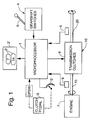
- a powershift transmission control system includes a microprocessor 1, a display 2 on an operator's control panel 2', a plurality of gearshift switches 4 which are selectively actuated by manually moving a gearshift lever 6, and a plurality of transmission clutches 8 associated with a transmission 10 which transmit power from a rotating power input shaft 15 to a power output or vehicle drive shaft 20.
- An engine 7 unidirectionally rotates shaft 15 and a sensor 9 senses rotation of shaft 15 to provide output signals representing engine speed.
- An operator-actuated clutch pedal 3 controls a potentiometer 3' and the output signal from the potentiometer is applied to microprocessor 1 to develop modulating signals which are applied to a final set of clutches in transmission 10.
- the clutch pedal 3 also actuates a clutch pedal switch CPSW when the pedal is depressed to its limit of travel.
- the control system is admirably suited for controlling the transmission of a tractor but it will be obvious that it may also be used to control the transmission of other vehicles or machines.
- Microprocessor 1 periodically samples the clutch pedal switch, the output of potentiometer 3', the switches 4, and the outputs of output and input shaft speed sensors 5 and 9, and in response to the sensed conditions controls transmission clutches 8 to "select gears", i.e. select the direction and rate of rotation of output shaft 20 relative to input shaft 15.
- the transmission control system of Figure 1 is similar to that disclosed in US-A-5.012.690 and reference may be made thereto for a more detailed explanation of the system operation.
- the system of Figure 1 differs from that disclosed in said patent in that (1) the program executed by microprocessor 1 to control shifting is modified and (2) gear ratios within the transmission 10 (shown in Figure 3) have been modified.
- Figure 3 is a schematic planar development of a powershift transmission having 18 forward gear ratios and 9 reverse gear ratios.
- the transmission is housed in a casing 12 and has a drive shaft 15 with a power input end 16 adapted to be driven by engine 7.
- the output end 17 of drive shaft IS serves as a power take-off.
- An output shaft 20 drives the tractor wheels or other load in a conventional manner.
- the transmission 10 has an input clutch section comprising a set 30 of three gears 31, 32, 33 and a set 70 of three clutches 71, 72, 73, a center clutch section comprising a set 40 of three gears 41, 42, 43 and a set 75 of three clutches 76, 77, 78, and an output clutch section comprising a set 60 of two forward gears 53, 62, a set 80 of two forward clutches 81, 82, a reverse gear 63 and a reverse clutch 83.
- a drive pinion 18 is rigidly secured to drive shaft 15 and when shaft 15 is rotated pinion 18 drives the gears 31, 32 and 33 which have different numbers of teeth and are mounted for free rotation on shafts 21, 22 and 23, respectively.
- Electro-hydraulic clutches 71, 72 and 73 are affixed to shafts 21, 22 and 23, respectively, and when one of these clutches is energized it couples drive power from one of the gears 31, 32 or 33 to one of the shafts 21, 22 or 23.
- the shafts 21, 22 and 23 are coupled together by gears 35, 36 and 37 which are all the same size so that all three shafts are driven at the same speed ratio relative to drive shaft 15, this ratio being determined by which one of the clutches 71, 72 or 73 is energized.
- Gears 41, 42 and 43 are differently sized and are mounted for free rotation on shafts 21, 22 and 23, respectively.
- Clutches 76, 77 and 78 are affixed to shafts 21, 22 and 23, respectively, and may be selectively energized to drive one of the gears 41, 42 or 43 at the speed of the shafts 21, 22 and 23.
- Gear 42 engages gear 43 which in turn engages a transfer gear 47 fixed on a transfer hub assembly 45.
- Gear 41 engages a transfer gear 46 fixed on the transfer hub assembly. Therefore, if any one of the gears 41, 42 or 43 is driven, all of the gears and the transfer hub assembly 45 are driven.
- the transfer hub assembly 45 may be driven at one of three speed ratios relative to the shafts 21, 22 and 23. Furthermore, since shafts 21, 22 and 23 may be driven at one of three speed ratios relative to drive shaft 15, because of the differently sized gears 31, 32 and 33, it is clear that the transfer hub assembly 45 may be driven at one of nine speed ratios relative to the drive shaft, the ratio depending on which one of the input section clutches 71, 72 or 73 and which one of the center section clutches 76, 77 or 78 is energized.
- the transfer hub assembly 45 is mounted in the casing 12 for free rotation concentric with drive shaft 15 and serves to transfer drive power to the output section.
- a transfer gear 49 affixed to the transfer hub assembly 45, engages a gear 53 which is mounted for free rotation on output shaft 20.
- a high speed final clutch 81 is affixed to shaft 20 and when clutch 81 is energized to drive gear 51 the shaft is driven at one of nine forward speed ratios, designated 1H, 2H...9H, within a high range H.
- the transfer gear 49 also drives a gear 55a which, with a gear 55b, is attached to a shaft 55.
- Gear 55b drives a gear 57 which is affixed to a shaft 26.
- a low speed final clutch 82 is affixed to shaft 26 while a gear 62 is mounted for free rotation on the shaft.
- clutch 82 is energized to drive gear 62
- gear 62 drives gear 61 which is affixed to the output shaft 20.
- the low speed final clutch 82 is engaged, the output shaft 20 is driven at one of nine forward speed ratios, designated 1L, 2L...9L within a low range L.
- the output shaft 20 may be driven at one of 18 forward speed ratios relative to input shaft 15 by simultaneously energizing one electro-hydraulic clutch in each of the clutch sets 70, 75 and 80.
- Table I shows, for each of these ratios, the selected "gear" and the clutches which are energized.
- An operator may initiate an upshift by moving the gearshift lever 6 to a forward upshift position.
- the microprocessor periodically senses gearshift switches 4 and, if the lever 6 is in the forward upshift position the microprocessor outputs signals to the clutches in the transmission 10 to select the next highest gear. This continues as long as the lever position is not changed or until the highest gear (9H) is reached.
- a downshift is accomplished by moving the gearshift lever 6 to a forward downshift position. Assuming the transmission is in the highest gear (9H) it is successively shifted through all gears until the lowest gear 1L is reached or until the shift lever 6 is moved out of the forward downshift position.
- the tractor In most heavy load applications, the tractor is generally operated in a range of two or three gears. If this range should include gears 9L and 1H an operator will experience a range shift each time a shift is made between these gears. In accordance with the principles of the present invention, the number of range shifts is reduced by modifying the prior art transmission as indicated in Table II.
- the input/output ratio for gear 8L is made substantially equal to the ratio for gear 1H and the ratio for gear 9L is made substantially equal to the ratio for gear 2H. This is most easily accomplished by changing the size of the low range gear 82 in the output clutch set 80.
- the shift control routine executed by microprocessor 10 is modified as subsequently described so that on upshifting the sequence is 1L, 2L,...7L, 8L, 9L, 3H, 4H,...9H and on downshifting the sequence is 9H, 8H,...2H, 1H, 7L, 6L,...1L.
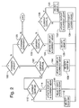
- FIG. 2 is a flow diagram illustrating that portion of a program executed by microprocessor 1 to control shifting in accordance with the sequence set forth in Table II.
- the microprocessor repeatedly samples the gearshift switches 4, the output of clutch pedal potentiometer 3' and the clutch pedal switch CPSW. Values representing the states of the switches and the position of the potentiometer are stored in memory registers within the microprocessor and used to control the clutches in transmission 10 during execution of the microprocessor program.
- the stored value representing the last sensed condition of the gearshift switches 4, (representing the position of gearshift lever 6), is tested to see if the gearshift lever is in the forward upshift position. If the test proves true then at step 102 a register CG is tested.
- Register CG stores the current gear value, that is, the gear from which the transmission is being shifted.
- the test at step 102 determines if the current gear is 9L. If it is, the display 2 and the register CG are updated at step 104 to indicate gear 3H and at step 106 the clutches are set to select gear 3H. This completes the gear shift routine as it relates to the present invention.
- step 110 register CG is tested to see if the current gear is 9H. If the current gear is 9H then further upshifting is not possible. The clutches are set at step 112 to select gear 9H.
- step 110 If the test at step 110 shows that the current gear is not 9H then the display 2 and value in register CG are updated at step 114 to represent the next higher gear. At step 116 the clutches are set to select the next higher gear.
- step 100 proves false and the program branches to step 120. Since the gearshift lever is in the forward downshift position the test at step 120 proves true and the program advances to step 122 where the value in CG is tested to see if the current gear is 1H. If it is, the display 2 and the value in register CG are updated at step 124 to indicate gear 7L and at step 126 the clutches are set to select gear 7L.
- step 122 If the test at step 122 shows that the current gear is not 1H then CG is tested at step 128 to see if the current gear is 1L. If it is, further downshifting is not possible. At step 130 the processor sets the clutches so that gear 1L continues to be selected.
- the display 2 and register CG are updated at step 132 to indicate the next lower gear.
- the microprocessor sets the clutches to select the next lower gear.
- the present invention provides a method and apparatus for reducing the number of range shifts in a powershift transmission.
- This improved shifting performance is obtained at the expense of a reduction in the overall range of input/output ratios but requires only one gear change and minor modification in the microprocessor program.
- the invention has been described by reference to a powershift transmission having three clutch sections and 18 forward gear speeds, it is equally applicable to powershift transmissions having a different number of clutch sections or a different number of forward gear speeds. Also, it is not necessary that the number of overlapping gear ratios be two.
- the upshift sequence may be 1L, 2L, etc.
- the downshift sequence may be NH,(N-1)H,....1H, (N-k)L, (N-k-1)L...1L where k is the number of ratios in one range which are substantially equal to respective ratios in the other range.
Landscapes
- Engineering & Computer Science (AREA)
- General Engineering & Computer Science (AREA)
- Mechanical Engineering (AREA)
- Control Of Transmission Device (AREA)
- Structure Of Transmissions (AREA)
Applications Claiming Priority (2)
| Application Number | Priority Date | Filing Date | Title |
|---|---|---|---|
| US07/987,184 US5337624A (en) | 1992-12-08 | 1992-12-08 | Powershift transmission with overlapping ranges of ratios |
| US987184 | 1992-12-08 |
Publications (2)
| Publication Number | Publication Date |
|---|---|
| EP0601645A1 true EP0601645A1 (de) | 1994-06-15 |
| EP0601645B1 EP0601645B1 (de) | 1997-02-26 |
Family
ID=25533085
Family Applications (1)
| Application Number | Title | Priority Date | Filing Date |
|---|---|---|---|
| EP93203388A Expired - Lifetime EP0601645B1 (de) | 1992-12-08 | 1993-12-03 | Getriebeschaltung ohne Unterbrechung des Antriebs mit sich überschneidenden Gangbereichen |
Country Status (3)
| Country | Link |
|---|---|
| US (1) | US5337624A (de) |
| EP (1) | EP0601645B1 (de) |
| DE (1) | DE69308271T2 (de) |
Cited By (6)
| Publication number | Priority date | Publication date | Assignee | Title |
|---|---|---|---|---|
| EP0971156B1 (de) * | 1995-03-07 | 2003-09-17 | Deere & Company | Nebenwellengetriebe |
| WO2004018250A3 (de) * | 2002-08-21 | 2004-04-01 | Zahnradfabrik Friedrichshafen | Verfahren zum steuern eines antriebsst5ranges eines fahrzeugs |
| US7288040B2 (en) | 2002-08-21 | 2007-10-30 | Zf Friedrichshafen Ag | Method for controlling the drive train of a vehicle |
| WO2018147779A1 (en) * | 2017-02-08 | 2018-08-16 | Scania Cv Ab | A gearbox for vehicles |
| WO2018147780A1 (en) * | 2017-02-08 | 2018-08-16 | Scania Cv Ab | A gearbox for vehicles |
| WO2018147781A1 (en) * | 2017-02-08 | 2018-08-16 | Scania Cv Ab | A gearbox for vehicles |
Families Citing this family (1)
| Publication number | Priority date | Publication date | Assignee | Title |
|---|---|---|---|---|
| JP2006105319A (ja) * | 2004-10-07 | 2006-04-20 | Jatco Ltd | 自動変速機のレンジ認識装置及び変速制御装置 |
Citations (3)
| Publication number | Priority date | Publication date | Assignee | Title |
|---|---|---|---|---|
| DE2645957A1 (de) * | 1976-10-12 | 1978-04-13 | Fendt & Co Xaver | Zahnraederwechselgetriebe in gruppenbauweise |
| EP0427459A1 (de) * | 1989-11-04 | 1991-05-15 | Toyota Jidosha Kabushiki Kaisha | Schaltungssteuerungssystem eines automatischen Getriebes |
| US5233525A (en) * | 1990-08-28 | 1993-08-03 | Case Corporation | Electronic control for transmission gear skip shift |
Family Cites Families (5)
| Publication number | Priority date | Publication date | Assignee | Title |
|---|---|---|---|---|
| US4576065A (en) * | 1984-09-12 | 1986-03-18 | Eaton Corporation | Automatic transmission controls with multiple downshift off-highway mode |
| US4916979A (en) * | 1988-04-18 | 1990-04-17 | Eaton Corporation | On-grade shift logic with provision for skip downshifts |
| US4852006A (en) * | 1988-04-18 | 1989-07-25 | Eaton Corporation | Amt off-highway downshift logic |
| US4947331A (en) * | 1988-07-25 | 1990-08-07 | Eaton Corporation | Upshift logic |
| US5012690A (en) * | 1989-12-01 | 1991-05-07 | Ford New Holland, Inc. | Programmable shuttle shifting in transmissions |
-
1992
- 1992-12-08 US US07/987,184 patent/US5337624A/en not_active Expired - Fee Related
-
1993
- 1993-12-03 EP EP93203388A patent/EP0601645B1/de not_active Expired - Lifetime
- 1993-12-03 DE DE69308271T patent/DE69308271T2/de not_active Expired - Fee Related
Patent Citations (3)
| Publication number | Priority date | Publication date | Assignee | Title |
|---|---|---|---|---|
| DE2645957A1 (de) * | 1976-10-12 | 1978-04-13 | Fendt & Co Xaver | Zahnraederwechselgetriebe in gruppenbauweise |
| EP0427459A1 (de) * | 1989-11-04 | 1991-05-15 | Toyota Jidosha Kabushiki Kaisha | Schaltungssteuerungssystem eines automatischen Getriebes |
| US5233525A (en) * | 1990-08-28 | 1993-08-03 | Case Corporation | Electronic control for transmission gear skip shift |
Cited By (10)
| Publication number | Priority date | Publication date | Assignee | Title |
|---|---|---|---|---|
| EP0971156B1 (de) * | 1995-03-07 | 2003-09-17 | Deere & Company | Nebenwellengetriebe |
| WO2004018250A3 (de) * | 2002-08-21 | 2004-04-01 | Zahnradfabrik Friedrichshafen | Verfahren zum steuern eines antriebsst5ranges eines fahrzeugs |
| US7288040B2 (en) | 2002-08-21 | 2007-10-30 | Zf Friedrichshafen Ag | Method for controlling the drive train of a vehicle |
| US7344475B2 (en) | 2002-08-21 | 2008-03-18 | Zf Friedrichshafen Ag | Method for controlling a drivetrain of a vehicle |
| WO2018147779A1 (en) * | 2017-02-08 | 2018-08-16 | Scania Cv Ab | A gearbox for vehicles |
| WO2018147780A1 (en) * | 2017-02-08 | 2018-08-16 | Scania Cv Ab | A gearbox for vehicles |
| WO2018147781A1 (en) * | 2017-02-08 | 2018-08-16 | Scania Cv Ab | A gearbox for vehicles |
| US10830323B2 (en) | 2017-02-08 | 2020-11-10 | Scania Cv Ab | Gearbox for vehicles |
| US10871212B2 (en) | 2017-02-08 | 2020-12-22 | Scania Cv Ab | Gearbox for vehicles |
| US11193568B2 (en) | 2017-02-08 | 2021-12-07 | Scania Cv Ab | Gearbox for vehicles |
Also Published As
| Publication number | Publication date |
|---|---|
| EP0601645B1 (de) | 1997-02-26 |
| DE69308271T2 (de) | 1997-06-12 |
| DE69308271D1 (de) | 1997-04-03 |
| US5337624A (en) | 1994-08-16 |
Similar Documents
| Publication | Publication Date | Title |
|---|---|---|
| EP0129341B1 (de) | Getriebe mit eingangsseitiger Doppelkupplung | |
| EP0595496B1 (de) | Halbautomatische Schaltdurchführung | |
| JP3462154B2 (ja) | オートマチック式伝動装置用の切換装置 | |
| JP3442682B2 (ja) | 自動車の自動変速機用表示装置 | |
| US4610177A (en) | Preselected multiratio transmission | |
| US7437963B2 (en) | Power transmission | |
| US5127288A (en) | Shift control system with an automatic first sequence and a manual second sequence of gear stages | |
| HK91596A (en) | Gear-shifting device for an automatic transmission of a motor vehicle | |
| CA2125816A1 (en) | Gearshift Mechanism | |
| CA2049242A1 (en) | Mode control for mechanical transmission system with semi-automatic shift implementation and manual and automatic shift preselection modes | |
| KR890701388A (ko) | 전동장치 | |
| EP0601645B1 (de) | Getriebeschaltung ohne Unterbrechung des Antriebs mit sich überschneidenden Gangbereichen | |
| EP0034411A2 (de) | Drehbares Getriebe | |
| US6085606A (en) | Mechanical transmission with reduced ratio steps in upper transmission ratios | |
| JPH0320158A (ja) | 自動変速機のレンジ選択装置 | |
| US5333709A (en) | Slipping clutch creeper | |
| US2892358A (en) | Multi speed, lever controlled transmission | |
| JPS645177B2 (de) | ||
| GB2304835A (en) | Control of gearshifting in an automatic transmission in series with a manual range gearbox | |
| JPS5888248A (ja) | 変速機及び該変速機を備える競争用オ−トバイ | |
| EP0725233A3 (de) | Fahrschalter für Lastschaltgetriebe | |
| JPH04282066A (ja) | 複合クラッチ付多段変速機の変速制御装置 | |
| JP3019277B2 (ja) | 動力車両の変速装置 | |
| JPS604650A (ja) | 変速機 | |
| RU1773746C (ru) | Коробка передач |
Legal Events
| Date | Code | Title | Description |
|---|---|---|---|
| PUAI | Public reference made under article 153(3) epc to a published international application that has entered the european phase |
Free format text: ORIGINAL CODE: 0009012 |
|
| AK | Designated contracting states |
Kind code of ref document: A1 Designated state(s): DE FR GB IT |
|
| 17P | Request for examination filed |
Effective date: 19941122 |
|
| 17Q | First examination report despatched |
Effective date: 19950928 |
|
| RAP1 | Party data changed (applicant data changed or rights of an application transferred) |
Owner name: NEW HOLLAND U.K. LIMITED |
|
| GRAG | Despatch of communication of intention to grant |
Free format text: ORIGINAL CODE: EPIDOS AGRA |
|
| GRAH | Despatch of communication of intention to grant a patent |
Free format text: ORIGINAL CODE: EPIDOS IGRA |
|
| GRAH | Despatch of communication of intention to grant a patent |
Free format text: ORIGINAL CODE: EPIDOS IGRA |
|
| GRAA | (expected) grant |
Free format text: ORIGINAL CODE: 0009210 |
|
| AK | Designated contracting states |
Kind code of ref document: B1 Designated state(s): DE FR GB IT |
|
| REF | Corresponds to: |
Ref document number: 69308271 Country of ref document: DE Date of ref document: 19970403 |
|
| ET | Fr: translation filed | ||
| ITF | It: translation for a ep patent filed | ||
| PLBE | No opposition filed within time limit |
Free format text: ORIGINAL CODE: 0009261 |
|
| 26N | No opposition filed | ||
| PGFP | Annual fee paid to national office [announced via postgrant information from national office to epo] |
Ref country code: GB Payment date: 19990917 Year of fee payment: 7 |
|
| PGFP | Annual fee paid to national office [announced via postgrant information from national office to epo] |
Ref country code: FR Payment date: 19991018 Year of fee payment: 7 |
|
| PGFP | Annual fee paid to national office [announced via postgrant information from national office to epo] |
Ref country code: DE Payment date: 19991020 Year of fee payment: 7 |
|
| PG25 | Lapsed in a contracting state [announced via postgrant information from national office to epo] |
Ref country code: GB Free format text: LAPSE BECAUSE OF NON-PAYMENT OF DUE FEES Effective date: 20001203 |
|
| GBPC | Gb: european patent ceased through non-payment of renewal fee |
Effective date: 20001203 |
|
| PG25 | Lapsed in a contracting state [announced via postgrant information from national office to epo] |
Ref country code: FR Free format text: LAPSE BECAUSE OF NON-PAYMENT OF DUE FEES Effective date: 20010831 |
|
| REG | Reference to a national code |
Ref country code: FR Ref legal event code: ST |
|
| PG25 | Lapsed in a contracting state [announced via postgrant information from national office to epo] |
Ref country code: DE Free format text: LAPSE BECAUSE OF NON-PAYMENT OF DUE FEES Effective date: 20011002 |
|
| PG25 | Lapsed in a contracting state [announced via postgrant information from national office to epo] |
Ref country code: IT Free format text: LAPSE BECAUSE OF NON-PAYMENT OF DUE FEES;WARNING: LAPSES OF ITALIAN PATENTS WITH EFFECTIVE DATE BEFORE 2007 MAY HAVE OCCURRED AT ANY TIME BEFORE 2007. THE CORRECT EFFECTIVE DATE MAY BE DIFFERENT FROM THE ONE RECORDED. Effective date: 20051203 |